
Related Manuals for MIMAKI CF2 Series


Summary of Contents for MIMAKI CF2 Series
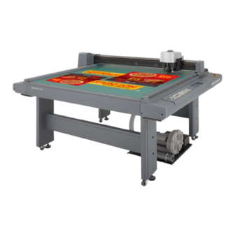
- Page 1 FLAT BED CUTTING PLOTTER CF2 Series CF2-0912 / 1215 / 1218 T model TD model TF model OPERATION MANUAL MIMAKI ENGINEERING CO., LTD. URL: http://mimaki.com/ D201373-17...
- Page 2 Correct handling procedure shall be followed according to this Operation manual. In the case where MIMAKI-designated cable is not used for the connection of this device, limits provided by VCCI rules can be exceeded. To prevent this, use of MIMAKI-designated cable is essential for the connection of this device.
- Page 3 FOREWARD Congratulations on your purchase of a “CF2- Series” of flat bed cutting plotter. This Operation Manual is intended for T-head model, TD-head model,and TF-head model,under the “CF2-Series” Any function for which no head name is designated is common to all models of heads. Please read and fully understand this manual before putting the machine into service.
-
Page 5: Table Of Contents
TABLE OF CONTENTS Installation Site........................ix Restriction in use ........................x FOR SAFE OPERATION....................... xi For safe operation ........................xiii Precautions in installation......................xiv HOW TO READ THIS INSTRUCTION MANUAL .............xv Structure of this Instruction Manual ......................xvi FEATURES OF THE DEVICE ................... xvii CHAPTER1 SET-UP INSTALLATION SITE ..............................1-2 CHECKING THE ACCESSORIES ..........................1-4... - Page 6 CHAPTER2 BASIC OPERATION BASIC OPERATION ON THE LOCAL MENU ....................2-2 LOCAL menu ................................2-2 MODE SET menu ..............................2-2 Basic operation on the LOCAL menu......................2-3 BASIC OPERATION FLOW CHART........................2-5 MOVING THE HEAD..............................2-6 Moving the head by “VIEW” function ......................2-6 Moving the head by the jog keys ........................2-7 FIXING A WORK................................2-8 Fixing a work that is comparatively light in weight ................2-8 Fixing heavy-weight packing etc........................2-9...
- Page 7 TOOLS ARE NOT ALIGNED TO EACH OTHER [TOOL ADJUST]..........3-6 Flowchart of checking and adjusting procedures..................3-6 General explanation of the adjustment of tools ..................3-7 Adjustment of the cutter.............................3-7 Adjustment of the offset..........................3-10 Adjustment of the roller ..........................3-11 How to adjust the tools............................ 3-15 TROUBLESHOOTING..............................
- Page 8 How to display the register mark setting on LCD ................. 5-11 Settings for detection of marks........................5-12 Settings for detect.............................. 5-14 How to detect Register mark ......................... 5-15 CONTINUOUS CUT WITH REGISTER MARK....................5-17 INITIALIZE THE REGISTER MARK SCALE ADJUSTMENT [SC.CLR]........... 5-18 CHAPTER6 SELF-TEST CONFIRMATION OF CUTTING QUALITY ONLY BY THE SINGLE UNIT OF THE DEVICE [SELF TEST]..................................6-2...
-
Page 9: Installation Site
Installation Site The structure of model name is as follows. Head type - Presence of Mark sensor Model name - Size Model Name: CF2 Size 0 9 1 2 1 2 0 0 × 9 0 0 mm 1 2 1 5 1... -
Page 10: Restriction In Use
Restriction in use Restriction in use This device are limited to the user who understands this dangerousness completely. Restriction for user This device shall get proper training. Limit to the user those who got proper training to operate. Restriction area Set up the restriction area for This device within the range indicated below. -
Page 11: For Safe Operation
FOR SAFE OPERATION Prior to using this device, be sure to read this Operation manual and become fully familiar with its operation method and usage cautions. Pictorial signs Pictorial signs are used in this Operation manual for safe operation of and in prevention of damages to the device. - Page 12 MIMAKI office for repair. Never repair your device by yourself since it is very dangerous for you to do Power supply and voltage Leave maintenance to a serviceman •...
- Page 13 For safe operation CAUTION Use the following electrical specifications Do not dress baggy suits and accessories • Be sure to connect the power cable • Do not work with dressing baggy to a power outlet with the following suits and any accessories, and also electrical specifications.
-
Page 14: Precautions In Installation
Precautions in installation CAUTION A place exposed to direct sunlight A place that vibrates • Do not install the device at a place • The device will fail to give correct where the temperature of the cut results if installed in a place that panel surface exceeds 60°C. -
Page 15: How To Read This Instruction Manual
HOW TO READ THIS INSTRUCTION MANUAL Name of function shown on LCD List of values that can be set Gives the description of operating procedure. Indication on LCD is Number of step of bracketed as operating [INTERFACE]. procedure Indicates the key to LCD display be used to select a function from indica-... -
Page 16: Structure Of This Instruction Manual
Structure of this Instruction Manual Chapter 1 Set-up This chapter describes the procedures to be taken after the unpacking to specify functions that are required for the connection of this device to your computer. Chapter 2 Basic operation This chapter describes normal operation of the device such as the replacing/attaching of tools or works. Chapter 3 When abnormal conditions are encountered This chapter describes how to correct troubles after the occurrence of an abnormal condition on the device. -
Page 17: Features Of The Device
FEATURES OF THE DEVICE The device is capable of cutting heavy-weight materials and solid materials. The device performs high-pressure cutting to permit the maximum cutting weight of 1.5 kg (5.0 kg for TD- and TF-heads). It also permits the setting of heavy-weight materials as heavy as 25 mm. With its tangential control that demonstrates its capability particularly when cutting hard materials, the device is able to cut, as desied, many different kinds of materials such as high-intensity reflective sheet, sand blast rubber, industrial sheet rubber and corrugated board. - Page 18 High-quality performance with its most-advanced functions, Start/end point correction In the case of processing heavy-weight works, works can be easily cut out by correcting the start and end posi- tions for cutting. Pressure correction In the case of cutting heavy-weight works, works can be fully cut with no portion remained uncut by correct- ing the pressure employed to lower the tool.
- Page 19 CHAPTER 1 SET-UP This chapter describes the procedure to be taken after the unpacking to specify functions that are required for the connection of this device to your computer. Table of Contents ...............................1-2 INSTALLATION SITE ..........................1-4 CHECKING THE ACCESSORIES ............................1-5 EFFECTIVE CUTTING AREA ........................1-6 CONFIGURATION AND FUNCTION...
-
Page 20: Installation Site
INSTALLATION SITE Install the device at a place where the below-stated installation area is provided. • Place nothing within an installation area. If a thing is placed, the risk of tripping over will be caused. Installation area (CF2-0912) 1000mm 3595mm 1000mm 1000mm 1000mm... - Page 21 INSTALLATION SITE Installation area (CF2-1218) 1000mm 3895mm 1000mm 1000mm 1000mm 4357mm...
-
Page 22: Checking The Accessories
CHECKING THE ACCESSORIES Accessories differs with the models of heads and applications. Check the accessories referring to the accompany- ing “Accessory list.” If you find any missing accessory or damaged one, contact your local dealer or MIMAKI office. -
Page 23: Effective Cutting Area
EFFECTIVE CUTTING AREA The maximum effective cutting areas by the models of devices are given below. The maximum cutting area does not change by the models of heads (T-head, TD-head, and TFhead) Maximum effective Y axis cutting area X axis Model name X axis (mm) Y axis (mm) -
Page 24: Configuration And Function
CONFIGURATION AND FUNCTION Main unit Illustration: CF-0912 (TD, TF, T) Name Function Y bar Moves the head in Y direction Electrical box PCBs or the like are built in this box. Head Tools are attached to the head. Tools that can be set to the head dif- fers with the models of heads. - Page 25 CONFIGURATION AND FUNCTION Right-hand side face of the electrical box Name Function Power connector To be connected to the power cable of the plotter. Main power switch Used to turn on/off the main power of this device. Normally set it to the on state.
-
Page 26: Head
Head Front face Name Function Head securing screw Used to fix the head on the Y bar. Loosen it when adjusting the height of the head or removing the head. Head C A marking roller or a high-pressure cutter is attached to the head C. (Only to TD- / TF-head) Mark sensor Used to detect the square mark. -
Page 27: Left-Hand Side Face
CONFIGURATION AND FUNCTION Left-hand side face Name Function Height adjusting knob Used to adjust the height of the head. Height adjusting bar Used to adjust the height of the head in accordance with the thickness of a work to be used. -
Page 28: Operation Panel
Operation panel PAGE POWER ORIGIN REMOTE VACUUM E N D LOCAL 1-10... - Page 29 CONFIGURATION AND FUNCTION Name Representation Function POWER ON switch Used to turn ON the power to the device. POWER lamp Lights up (in green) when the power to the device is turned on. LCD indicates states of the device and [LOCAL]...
-
Page 30: Connecting The Cables
CONNECTING THE CABLES • Be sure to turn off the the power to the device in prior when connecting the signal wire cable for the blower, interface cable and the power cable. If not, there will be a fear of the arising of electric shock hazards and damage to the device. -
Page 31: Connecting The Interface Cable
Connecting the interface cable The device is equipped as standard with an interface conforming to RS-232C. Use a MIMAKI-recommended interface cable or a cable that matches your computer. Turn off the power to the plotter and that to the personal computer. - Page 32 Insert the power cable for the plotter into the AC inlet of the electrical box. Power cable for the main unit Insert the other end of the power cable into the 3P receptacle. • In the case where a 2-pole receptacle is used, additionally use the installation adapter supplied with the unit as an acces- sory.
-
Page 33: Turning The Power On/Off
TURNING THE POWER ON/OFF The device is provided with separate switches for turning the power on and off. Turn on/off the power to the device following the procedure described below. • Do not place any thing other than a work on the cutting panel when turning the power on. Turning the power on causes the head to travel to the retracted point located at the lower right of the cutting panel. -
Page 34: Emergency Stop
EMERGENCY STOP In an emergency, the device can be stopped at once. How to stop the device in an emergency Press the EMERGENCY button. This causes the device to stop its operation and turns the power off. How to reset the emergency stop Turn the EMERGENCY button clockwise for unlocking. -
Page 35: Local/Remote Modes
LOCAL/REMOTE MODES The operation mode is changed over alternately between the LOCAL mode and the REMOTE mode every time key is pressed. LOCAL mode and the indication on the LCD Under LOCAL mode, the head travels, functions of the device are set, and data from the personal computer are received. -
Page 36: Remote Mode And The Indications On The Lcd
REMOTE mode and the indications on the LCD Under the REMOTE mode, cutting or plotting can be carried out in accordance with data received. The LCD indicates cutting (plotting) conditions and the capacity of data received. Capacity of data decreases as you proceeds with cutting (plotting). The POWER ON key, POWER OFF key, the key and the... -
Page 37: Matching The Functions Of The Device To The Specifications Of The Computer
MATCHING THE FUNCTIONS OF THE DEVICE TO THE SPECIFICATIONS OF THE COMPUTER The following explains how to set the functions required to connect the device to your personal computer. Setting communication conditions [INTERFACE] Communication conditions for the communication between the device and the computer to which the device is connected by way of RS232C. -
Page 38: Setting The Commands To Be Used [Mode Set] > [Command]
Enter the input values. < INTERFACE > 2 / 2 PARITY ODD > Press the key to enter the input values. STOP BITS 1 > HANDSHAKE XCODE > If you do not enter the input data, press the key. [LOCAL] 3... -
Page 39: Rendering The Set Values On The Personal Computer Effective [Mode Set] > [Command Sw]
MATCHING THE FUNCTIONS OF THE DEVICE TO THE SPECIFICATIONS OF THE COMPUTER Rendering the set values on the personal computer effective [MODE SET] > [COMMAND SW] The set values that are rendered effective are specified either those set on the operation panel or those set on the CAD. -
Page 40: Setting The Response Value With Respect To The Valid Area [Mode Set] > [Oh Unit]
Setting the response value with respect to the valid area [MODE SET] > [OH UNIT] The response value that is to be transmitted to the CAD in response to a valid area coordinate output command for the device is selected between the following. Set values INITIAL VALUE: The value of the max. -
Page 41: Setting The Command Origin [Mode Set] > [Origin]
MATCHING THE FUNCTIONS OF THE DEVICE TO THE SPECIFICATIONS OF THE COMPUTER Setting the command origin [MODE SET] > [ORIGIN] Adjust the position of the command origin of the device to the origin of the command origin of your CAD. Refer to the Instruction Manual for your CAD for the position of the command origin supported by the CAD. -
Page 42: Setting The Resolution (Gdp) [Mode Set] > [Gdp]
Setting the resolution (GDP) [MODE SET] > [GDP] Set the resolution of the device to that of your CAD. Refer to the instruction manual for your CAD for the resolu- tion supported by the CAD. GDP: Graphic Display Pitch Set values 0.025 mm : The resolution is set to 0.025 mm. -
Page 43: Setting For Automatic Head Retract [Auto View]
SETTING FOR AUTOMATIC HEAD RETRACT [AUTO VIEW] A period of time required to cause the head to start to travel to its retracted position after the completion of cutting (plotting). Retracted position Set values OFF: Automatic head retract is not performed. When one second has passed after the completion of cutting (plotting), the head starts to travel to the retracted position When three second has passed after the completion of cutting (plotting), the head starts to travel to the... - Page 44 Enter the input values. < MODE SET > 2 / 6 Press the key to enter the input values. AUTO VIEW 1 s > DUMMY CUT * ON > If you do not enter the input data, press the key. ONE STROKE *...
-
Page 45: Auto-Off Feature Of The Vacuum
AUTO-OFF FEATURE OF THE VACUUM The validity of the Auto-OFF feature can be set up. When the automatic head retraction function is set to 1s or 3s, the vacuum will turn off automatically after the head retracts. When the automatic head retraction function is off, the vacuum will not turn off automatically. While operating copy function, number cut function, or completing continuous square mark copy, will turn the vacuum off automatically, regardless of the automatic head retraction function. - Page 46 1-28...
- Page 47 CHAPTER 2 BASIC OPERATION In Chapter 2, normal operation of the device such as the attaching of tools or works. Table of Contents .......................2-2 BASIC OPERATION ON THE LOCAL MENU ..........................2-5 BASIC OPERATION FLOW CHART ...............................2-6 MOVING THE HEAD ................................2-8 FIXING A WORK ............................
-
Page 48: Basic Operation On The Local Menu
BASIC OPERATION ON THE LOCAL MENU LOCAL menu Various kinds of data and functions required for the connection with your personal computer are set. Function Description Reference page TOOL SELECTION Head and tool to be used are selected. P. 2-18 CONDITIONS Conditions for the tool selected using the [TOOL SELECTION] func- P. -
Page 49: Basic Operation On The Local Menu
BASIC OPERATION ON THE LOCAL MENU Z STROKE The height of the tool, in its lifted position, from the surface of a work P. 4-10 to the bottom of tool is specified. OH UNIT A value that is transmitted to the computer in return to the command P. - Page 50 Set the device in the LOCAL mode. Check first that no data received remain, and press the key to set the device in the LOCAL mode. Advance the LOCAL menu pages. Each press on the key will advance the page one by one. Each press on the key will return the page one by one.
-
Page 51: Basic Operation Flow Chart
BASIC OPERATION FLOW CHART BASIC OPERATION FLOW CHART The following is the basic operation flow chart. Refer to the page to be referred to for detailed explanation of each operation. Fixing the work ( P. 2-8) Attach a work in position. Attaching tools (... -
Page 52: Moving The Head
MOVING THE HEAD It is possible to move the head for easier operation when attaching a tool or a work on the device or executing test cut. The head can be moved in the following two different procedures: • Moving the head by “VIEW” function •... -
Page 53: Moving The Head By The Jog Keys
MOVING THE HEAD Moving the head by the jog keys Follow this procedure when attaching a tool or executing test cut or sample cut. Press a jog key to select the jog mode, and the following two functions can be carried out to move the head to a desired position with accuracy. -
Page 54: Fixing A Work
FIXING A WORK A work can be fixed on the device following one of the two procedures described below. • Fixing the work with vacuum • Fixing the work with adhesive tape • Thickness of works that can be attached on this device should not exceed 25mm. Four area marker labels are adhered on the cutting panel. -
Page 55: Fixing Heavy-Weight Packing Etc
FIXING A WORK • By aliging the mdia edge to the media guide, work can be set straight. Be sure to set the work within the Maximum effective cutting area. Work Guide • When EXPAND is set to ON with a sen- sor model or No sensor model, work guide may interrupt the maximum cut- ting area. -
Page 56: Adjusting The Blade
High-speed steel blade 30° ..For light-weight and soft works such as coated board and corrugated fiberboard. • Special blades and holders for tangential cutters are prepared in accordance with works. Please contact your local dealer or MIMAKI office for details. Loosen the dial stopper. Dial stopper Loosen the dial stopper counterclockwise to loosen it. -
Page 57: Swivel Blade
Follow the procedure described below when projecting the blade tip of the swivel cutter. • Special blades for the swivel cutters are prepared in accordance with works. Please contact your local dealer or MIMAKI office for details. Loosen the locknut. Locknut Loosen the locknut counterclockwise to loosen it. -
Page 58: Attaching The Tools
ATTACHING THE TOOLS The table below gives the heads (A, B and C) to which tools are attached with respect to the head models. This picture shows TD-head model. T-head TD-head TF-head Head model name Swievel blade Low-pressure tangential cutter High-pressure tangential cutter Creasing roller 2-12... -
Page 59: Attaching The Pen And The Swivel Blade
ATTACHING THE TOOLS Attaching the pen and the swivel blade If the head is in the lower position and a tool cannot be installed, lift the head.( P. 2-16) Loosen the screw in head A. Turn the screw A counterclockwise to loosen it. Open the holder right and left. -
Page 60: Attaching The Tangential Cutter
Attaching the tangential cutter Tangential cutter can be used with the head models excluding the P-head model. P. 2-16) If the head is in the lower position and a tangential cutter cannot be installed, lift the head. ( Loosen the stopper screw in the tangential cutter. Turn the stopper screw counterclockwise to loosen it. -
Page 61: Installing The Crease Roller
ATTACHING THE TOOLS Installing the crease roller The creasing roller can be installed on the head models excluding the P- and T-head models. The crease roller is attached to C of the TD-head model. The high-pressure tangential cutter can also be attached to it. -
Page 62: Adjusting The Height Of The Head
ADJUSTING THE HEIGHT OF THE HEAD After a work and the tools have been properly attached in position, adjust the height of the head in accordance with thickness of the work. Be sure to adjust the height of the head whenever you have changed a work to be used. •... - Page 63 ADJUSTING THE HEIGHT OF THE HEAD Tight the both fixing screws on the head alter- nately from the bottom screw first. Turn the fixing screws clockwise to tighten them. Fixing screw 2-17...
-
Page 64: Selecting A Tool [Tool Select]
SELECTING A TOOL [TOOL SELECT] Now, select a head and a tool to be used in the cases described below. • In the case where the pen number cannot be specified on the CAD. • In the case where [TEST CUT] function or [SELF TEST] function is executed on the device itself •... -
Page 65: Setting Cutting Conditions [Condition]
SETTING CUTTING CONDITIONS [CONDITION] Cutting conditions are set for the tool that has been selected in the [TOOL SELECT]. Setting items Cutting condition setting items differ with the tools. • In the case Approximate Type is set to “Arc” on the FineCut plotter settting, excesive pressure may applied and damage the cutter depend on the media type. - Page 66 Tangential Crease Swivel Setting item Description cutter roller blade Up angle The minimum angle required by the raised tool to ○ ○ ○ change the direction of cutting (marking). This reduces the degree by which the tool pries the work. Ring distance If minute line segments continue, a rounding distance ○...
-
Page 67: Set Values
SETTING CUTTING CONDITIONS [CONDITION] Tangential Crease Swivel Setting item Description cutter roller blade R50 speeds The speed that is employed when cutting an arc that is ○ 40 mm or more and less that 50 mm. If [OFF] is selected, the arc is cut at the previously specified speed.R50 speed. - Page 68 Marking conditions for the crease roller The following gives set values for crease conditions for the crease roller. Set values Speed: 2, 5, 10, 15, 20, 25, 30, 35, 40, 45, 50 (cm/s) Pressure: 1000 to 5000 (in increments of 100 g) Acceleration: 0.1 to 0.5 (in increments of 0.1 G) Up angle: 0 to 180 (in increments of 1°) Ring distance: 0.00 to 2.50 (in increments of 0.05 mm)
-
Page 69: Setting Cutting Conditions
SETTING CUTTING CONDITIONS [CONDITION] Setting cutting conditions The following describes how to establish cutting conditions for cutter 2 (tangential cutter) as an example. Once you have set cutting conditions, execute the [TEST CUT] function to check whether or not the cutting conditions are P. - Page 70 Set the RING DISTANCE and PRESS CORRECTION < CUTTER 2 > 3 / 4 to adequate value. RING DIS * 0 . 3 0 mm > PRESS COR * 0 g > ..Input a ring distance. RESERVE ..Input a press correction. •...
-
Page 71: Checking Cutting Conditions [Test Cut]
CHECKING CUTTING CONDITIONS [TEST CUT] Whenever you have changed cutting conditions or the tool(s) to be used, execute the “test cut”function to check the following P. 2-27) items. Refer to “Checking the status of tools” ( (1) Whether or not the cutting (plotting) conditions are proper Whether or not a work is properly cut or the finished plot has thin spots. - Page 72 Execute the [TEST CUT]. < TEST CUT > 1 / 1 Press the key, and the test cut will be executed. END KEY to START CE KEY to CANCEL To cancel the [TEST CUT] press the key. This restores the step of procedure 2 on the screen.
- Page 73 CHECKING CUTTING CONDITIONS [TEST CUT] Checking the status of tools Execute the [TEST CUT] function with the tools specified using the tool selecting function. Items to be checked for the tools are shown in the tables below. Point A Point B Point C Point D Point D’...
- Page 74 Check point Cause Corrective measure Reference page Cutting depth at C is excessive. The set value for the [START Set a smaller value for the P. 2-21 CORRECTION] is too large. [START CORRECTION]. The cutter is off-center. Conduct the “adjustment of the P.
-
Page 75: Checking The Status Of Tools
CHECKING CUTTING CONDITIONS [TEST CUT] Checking the status of tools Check the relation between the tools (th pen and the tangential cutter, and the pen and the crease roller) using the TEST CUT function. For this purpose, perform plotting first using the pen, then execute the test cut function using the tangential cutter or the crease roller at the same position to check the relation between the tools. - Page 76 Sample C The point from which the cutter starts is this side (or far side) of the predetermined start position. Corrective measure Adjust the set value for the [START CORRECTION] in [CUT- TING CONDITIONS] using the cutting condition setting func- tions.
- Page 77 CHECKING CUTTING CONDITIONS [TEST CUT] Sample F The cutter rotates clockwise (or counterclockwise) and the point from which the cutter starts is this side (or far side) of the prede- termined start position. Corrective measure Refer to the corrective measures for the samples B and C. Sample G The pattern is finished with rotated clockwise (or counterclock- wise) and the tangential cutter shifts to the right (or left) from the...
- Page 78 Sample I The point at which the cutter finishes cutting goes beyond (or does not reach) the predetermined end position, and the tangential cutter shifts to the right (or left) from the correct position. Corrective measure Refer to the corrective measures for the samples D and E. Sample J The cutter rotates clockwise (or counterclockwise), the point at which the cutter finishes cutting goes beyond (or does not reach)
-
Page 79: Setting The Cutting Area [Cut Area]
SETTING THE CUTTING AREA [CUT AREA] The cutting area is maximized when turning on the power to the device. The cutting area can be adjusted to the size of works placed on the device or set to a desired size. To specify a new cutting area, determine the lower left point (LL;... - Page 80 Align the tip of the tool to the lower left point of the desired cutting area. < AREA LL > [mm] ― 6 0 0 . 0 ― 4 5 0 .0 Move the tool using the jog keys until the tip of the tool meets the SPEED FAST >...
- Page 81 SETTING THE CUTTING AREA [CUT AREA] Enter the UR point. < AREA LL > [mm] Press the key to enter the input values. If you do not enter the 3 8 0 . 0 1 1 2 . 0 input data, press the key.
-
Page 82: Setting The Origin (Origin For Plotting)
SETTING THE ORIGIN (ORIGIN FOR PLOTTING) The origin is the reference point that is used for plotting, cutting and creasing. The plotting position can be moved by changing the location of the origin. Coordinate of the origin are always (0,0). If the head is moved using the jog keys, the coordinates of the head as from the origin are indicated on the LCD. -
Page 83: Interruption Of Processing (Plotting, Cutting Or Creasing)
INTERRUPTION OF PROCESSING (PLOTTING, CUTTING OR CREASING) Under the REMOTE mode, processing can be interrupted due to some reason. The following explains how to interrupt the process and the function that enables the settings to be changed after the interruption. How to interrupt/resume the process LOCAL key while the device is in opera- Press the... - Page 84 key to If the device is in the REMOTE mode, press the cause the device to enter the LOCAL mode. [LOCAL] 1 / 4 TOOL SELECT ――― > If some processing is being done, it will be interrupted. CONDITION ――― > TEST CUT ―――...
-
Page 85: Chapter3
CHAPTER 3 WHEN ABNORMAL CONDITIONS ARE ENCOUNTERED This chapter describes how to correct troubles in the event that desired cutting results are not obtained or a failure has occurred. Table of Contents .............3-2 IF ANY OF THE BELOW-STATED PHENOMENA TAKES PLACE .3-4 Corrugated board is cut out at flutes though creasing is performed [CONDITION] >... -
Page 86: If Any Of The Below-Stated Phenomena Takes Place
IF ANY OF THE BELOW-STATED PHENOMENA TAKES PLACE Cutting depth is insufficient. [CONDITION] > [PRESS CORRECT] If the cutter is lowered, the work may not be thoroughly cut out though the projecting amount of the blade tip is larger than the thickness of the work. In this case, the work can be cut out without fail by increasing the pressure applied to the descending cutter. - Page 87 IF ANY OF THE BELOW-STATED PHENOMENA TAKES PLACE How to adjust: Conduct the adjustment as given in the table below: Pattern θ θ Ta n g e n t Ta n g e n t line line How to adjust Set a correction angle to the positive side.
-
Page 88: Corrugated Board Is Cut Out At Flutes Though Creasing Is Performed [Condition] > [Press (Y)]
Corrugated board is cut out at flutes though creasing is performed [CONDITION] > [PRESS (Y)] When marking corrugated board along with flutes of the corrugated board, the pressure specified in [CUTTING CONDITIONS] can be so high as to break the board. How to adjust: Follow the adjusting procedure described below. -
Page 89: Square Mark Not Detected [Tool Adjust] > [Light Pointer]
Corrugated board is cut out at flutes though creasing is performed [CONDITION] > [PRESS (Y)] Square Mark not detected [TOOL Adjust] > [LIGHT POINTER] If a plotter fails to detect any registration mark properly, the possible cause is an error in the positional relation- ship between the mark sensor and the light pointer, or error in the setting of square mark detect. -
Page 90: Tools Are Not Aligned To Each Other [Tool Adjust]
Corrugated board is cut out at flutes though creasing is performed [CONDITION] > [PRESS (Y)] TOOLS ARE NOT ALIGNED TO EACH OTHER [TOOL ADJUST] If a plotting tool and a cutter or a plotting tool and a marking roller fail to finish patterns that lack in overlapping, the deviation between the tools has to be adjusted. -
Page 91: General Explanation Of The Adjustment Of Tools
Corrugated board is cut out at flutes though creasing is performed [CONDITION] > [PRESS (Y)] General explanation of the adjustment of tools Tools are adjusted with respect to the below-stated three items. (1) “Adjustment of the cutter” to adjust the low-pressure tangential cutter. (2) “Adjustment of the roller”... - Page 92 How to adjust: Follow the adjusting procedure given below. Pattern A has to be adjusted to correct the problem where the blade tip is out of the center of the cutter holder. Pattern A Sample pattern How to adjust Input a negative value as “A” that corre- Input a positive value as “A”...
- Page 93 Corrugated board is cut out at flutes though creasing is performed [CONDITION] > [PRESS (Y)] Adjustment of the θ angle The rotating angle of the tangential cutter is adjusted. Eliminate the difference in rotating angle between the plotted pattern and the cut pattern. Two different patterns are used for adjustment.
-
Page 94: Adjustment Of The Offset
Adjustment of the offset Offset amount of the cut pattern as from the plotted pattern is adjusted in terms of the X- and Y-aes. One pattern is used for adjustment. The illustration below indicates the size of the patterns and the cutting order. 30mm : Point from which cutting starts : Direction of cutting... -
Page 95: Adjustment Of The Roller
Corrugated board is cut out at flutes though creasing is performed [CONDITION] > [PRESS (Y)] Adjustment of the roller The roller is adjusted in three different ways as described below. (1) “Adjustment of the eccentricity” to adjust the eccentricity of the tools (2) “Adjustment of the θ... - Page 96 In pattern B, the tool is installed with tilted. Pattern B has to be adjusted so that horizontal lines and vertical lines are arranged in a straight line respectively along X- and Y-axes. Pattern B Sample pattern How to adjust Input a positive value as “B”...
- Page 97 Corrugated board is cut out at flutes though creasing is performed [CONDITION] > [PRESS (Y)] How to adjust: Follow the adjusting procedure given below. Sample pattern How to adjust If the cut pattern rotates clockwise as If the cut pattern rotates counter clockwise as compared with the plotted pattern, compared with the plotted pattern, increase the θ...
- Page 98 How to adjust: Follow the adjusting procedure given below. Sample pattern If the roller deviates to the right, increase If the roller deviates to the left, decrease the X How to adjust the X value for the roller. value for the roller. Sample pattern If the roller deviates upward, increase the If the roller deviates downward, decrease the Y...
-
Page 99: How To Adjust The Tools
Corrugated board is cut out at flutes though creasing is performed [CONDITION] > [PRESS (Y)] How to adjust the tools “TOOL SELECT” consists of two categories; i.e., the “adjustment of the cutter”, the “adjustment of the roller” and "circle θ adjust". The tool adjusting procedure is described below taking the “adjustment of the cutter 1”... - Page 100 To check the q angle, select the [TEST PATTERN]. < ADJUST > θ 2 / 3 CUTTERθ **. **> Plot the pattern using the pen, then cut the pattern with the tangential PATTERN No. * 1 > cutter. TEST PATTERN ―――...
-
Page 101: Troubleshooting
Is the lifting/lowering movement of the pen defec- Turn the power off. Then, move the head A up ― tive? and down. If the head fails to go up and come down normally, please contact your local dealer or MIMAKI office. 3-17... -
Page 102: Dotted Lines Or Blurred Lines Are Plotted
Dotted lines or blurred lines are plotted Cause Corrective measure Reference page Has the screw in head A loosened? Firmly re-tighten the screw in the head A. P. 2-13 Is the plotting speed too high? Decrease the plotting speed. P. 2-21 Is the plotting pressure insufficient? Increase the plotting pressure. -
Page 103: Troubles For Which Error Messages Are Given On The Lcd
TROUBLES FOR WHICH ERROR MESSAGES ARE GIVEN ON THE LCD If something is wrong with the device, a corresponding error message is given on the LCD. Causes of and corrective measures against such errors are described below. Errors that can be corrected by users The table below gives the errors that can be corrected by users. - Page 104 P. 5-11) Confirm the status and the settings described above. If still no registration mark is detected, contact your distributor or a sales office of Mimaki. ERROR 36 MARK DETECT Stop NO registration mark was detected. Stop data...
-
Page 105: Errors That Cannot Be Corrected By Users
If any of the errors described below has arisen, immediately turn of the power to the device. Wait for a while and re-turn on the power to the device. If the same message appears on the LCD, immediately turn the power off and contact your local dealer or MIMAKI office. Error message... - Page 106 3-22...
- Page 107 CHAPTER 4 APPLICATION FUNCTIONS This chapter describes helpful functions that facilitate operation. Table of Contents ............4-2 ASSIGNMENT OF PEN NUMBERS [MODE SET] > [PEN ASIGN] ........................4-4 RE-CUT OF THE SAME DATA [COPY] .........4-6 SETTING THE NUMBER CUT FUNCTION [MODE SET] > [MULTI-PASS] ..........4-8 SETTING THE ONE-STROKE CUTTING [MODE SET] >...
-
Page 108: Assignment Of Pen Numbers [Mode Set] > [Pen Asign]
ASSIGNMENT OF PEN NUMBERS [MODE SET] > [PEN ASIGN] Pen numbers included in data are assigned to tools of the device. As many as six pens can be assigned to the tools. Operating procedure is described in this section using the example given below. Pen 1 (Pen number in data to be plotted) →... - Page 109 ASSIGNMENT OF PEN NUMBERS [MODE SET] > [PEN ASIGN] Enter the input value. < PEN ASIGN > 2 / 6 If you do not enter the input data, press the key. PEN 1 HEAD * B > TOOL * CUTTER 2 > LOCAL]...
-
Page 110: Re-Cut Of The Same Data [Copy]
RE-CUT OF THE SAME DATA [COPY] Data that has been already cut can be re-cut in the off-line state. This means that the same data need not be trans- mitted from the computer in repetition. • Be sure to execute the “DATA CLEAR” to clear data from the receiving buffer before trans- mitting data to be copied. - Page 111 RE-CUT OF THE SAME DATA [COPY] Execute the [COPY]. < COPY > 1 / 1 Press the key to execute the copy function. END KEY to START CE KEY to CANCEL If you do not want to copy the object data, press the key.
-
Page 112: Setting The Number Cut Function [Mode Set] > [Multi-Pass]
SETTING THE NUMBER CUT FUNCTION [MODE SET] > [MULTI-PASS] The same data can be cut as many as five times by changing the pressure values. This allows the device to effi- ciently cut a work that cannot be thoroughly cut out by performing cutting once. A period of time required to judge a separating point between pieces of data can also be specified. - Page 113 SETTING THE NUMBER CUT FUNCTION [MODE SET] > [MULTI-PASS] Enter the input values. < MULTI PASS > 2 / 2 Press the key to enter the input values. If you do not enter the PRESS 3 7 0 0 g > input data, press the key.
-
Page 114: Setting The One-Stroke Cutting [Mode Set] > [One Stroke]
SETTING THE ONE-STROKE CUTTING [MODE SET] > [ONE STROKE] Received data on non-connected line segments illustrated below can be cut in such a manner as a one-stroke brush. To use the register mark sensor, this function will be rendered ineffective. Set values off : Single-stroke cutting is not performed. -
Page 115: Setting The Direction Of Rotation For The Coordinate Axis [Mode Set] > [Rotate]
SETTING THE DIRECTION OF ROTATION FOR THE COORDINATE AXIS [MODE SET] > [ROTATE] In the case where the command origin is established at the lower left of the cutting area, it is necessary to specify the direction of rotation for the coordinate axis in accordance with your CAD. Set values +90°: Lower right of the maximum effective cutting area –90°: Upper left of the maximum effective cutting area... -
Page 116: Setting The Cutter Stroke [Mode Set] > [Z Stroke]
SETTING THE CUTTER STROKE [MODE SET] > [Z STROKE] For data on a pattern that needs frequent lifting/lowering of the tangential cutter and the marking roller, the lifting amount of the tool should be shortened. This will reduce the total period of time required for cutting. Set values 7 mm: The tool goes up 7 mm above the surface of a work. -
Page 117: Setting The Unit To Be Used For Indication [Mode Set] > [Unit]
SETTING THE UNIT TO BE USED FOR INDICATION [MODE SET] > [UNIT] The unit to be used when indicating numerics on the LCD is specified. Set values mm: Numerics are indicated in millimeters. inch: Numerics are indicated in inches. Press the key several times until the LCD indicates [LOCAL]... -
Page 118: Setting The Dummy Cut Operation Of The Swievel Blade [Mode Set] > [Dummy Cut]
SETTING THE DUMMY CUT OPERATION OF THE SWIEVEL BLADE [MODE SET] > [DUMMY CUT] In the case where the swievel cutter is selected for the tool, a cutting operation is performed outside the effective cutting area so as to orient the blade tip of the swievel cutter to the advancing direction. Set values on: Dummy cut is not performed. -
Page 119: Alignment Of Mechanical Axes To Ruled Lines Printed [Axis Align]
ALIGNMENT OF MECHANICAL AXES TO RULED LINES PRINTED [AXIS ALIGN] If ruled lines such as scales are printed on a work, mechanical axes (X-axis, Y-axis) of the device need to be aligned to them. To set the mechanical axes, firstly establish an origin at the leftmost ruled line printed on the work in terms of the X-axis direction. - Page 120 Align the tip of the tool to point A. Operate the jog keys to align the tip of the tool to the rightmost one of < AXIS ALIGN > [mm] the ruled lines on the work. 0 0 . 0 0 0 0 . 0 0 Increase/decrease the speed and lift/lower the tip of the tool when neces- SPEED FAST >...
-
Page 121: Expand The Cutting Area [Expands]
EXPAND THE CUTTING AREA [EXPANDS] The Expand function expands the cutting area. In case of Seneor equipped model, and not using Mark detect function, able to expand the cutting area 30mm. This function only supports S (sensor equipped) model. • To use the square mark detect function with the sensor equipped model, set to OFF. - Page 122 Press the key to start origin initialize operation. *** ! WARNING *** • Every time change the EXPAND set ting, origin HEAD will move initialize operation executed for set of ORG. − PUSH END key − • In the case of set to ON, mark detect set ting becomes OFF automatically.
- Page 123 CHAPTER 5 REGISTER MARK DETECT FUNCTION This chapter describes “register mark detect” function. egister mark detect function only supports S (sensor equipped) model. Table of Contents ......................5-2 SETTING OF REGISTER MARK DETECT ...............5-3 PRECAUTIONS IN PREPARING DATA WITH REGISTER MARK ................
-
Page 124: Setting Of Register Mark Detect
SETTING OF REGISTER MARK DETECT This function detects a register mark automatically. Use this function to correct the inclination of the sheet loaded, the position of plotting origin, and the distance between register marks and then cut the contour of printed image. If the firmware version is older than 2.50, the register mark is circular. -
Page 125: Precautions In Preparing Data With Register Mark
PRECAUTIONS IN PREPARING DATA WITH REGISTER MARK There are some limitations on preparing data with register marks. In order to make full use of this function, read the following instruction carefully and prepare data with register mark. • The register mark described here is intended to detect the sheet inclination and the lengths along the X and Y axes. -
Page 126: Size Of The Register Mark
Size of the register mark Each side of the single register mark must be 5 - 30mm. Each side of the double register mark must be 10 - 30mm. The line width of mark shall be equal to or more than 0.2 mm and equal to or less than 0.5 mm. Refer to [The size of, and the distance between, register marks] ( P. -
Page 127: The Area Where Register Marks And Designs Can Be Arranged
PRECAUTIONS IN PREPARING DATA WITH REGISTER MARK The area where register marks and designs can be arranged The TP1 starting position must be 10mm or more away from the work left edge, and 30 mm or more away from the Available cutting area. Over 30mm needed from Within 20mm needed from plotting permitted area... -
Page 128: No-Plotting Area Around The Register Marks
No-plotting area around the register marks There must be no data or stain arround the register mark; otherwise a wrong origin may be detected or a mark read error can occur. ● If a wrong mark origin is detected, the cutting will be performed in a wrong area. 10mm Square mark size (5 to 30mm) Square Mark... - Page 129 PRECAUTIONS IN PREPARING DATA WITH REGISTER MARK Example of cause of wrong detection1: Layer of the offset printing is misaligned . • When printing with offset, square mark is printed in one color. Detected mark origin Mark origin Example of cause of wrong detection2: The diarnce between square marks (TP3 of pattern A and TP1 of pattern C, or TP2 of pattern A and TP1 of patternB) is less than 10mm.
- Page 130 Example of cause of wrong detection3: The distance between register marks(TP2&TP1, TP4&TP2) is smaller than the mark length. No plotting area Space larger than the mark length No plotting area Space larger than the mark length...
-
Page 131: The Size Of, And The Dhꞏ|Ance Between, Register Marks
PRECAUTIONS IN PREPARING DATA WITH REGISTER MARK The size of, and the dhꞏ|ance between, register marks The size (B) of a register mark suited for the distance (A) between the mark is as shown below. If the mark size (B) is too small relative to the distance (A), the marks may not be detected correctly. Be sure to prepare the register marks with an appropriate size. -
Page 132: Color Of Register Mark
Color of Register mark Black or white is recommended for the register mark color. Other corlors can be detected. However make sure to not use the same color as media(work). It is recommended to confirm ahead, either register mark is detectable. The register mark will not be deteced correctly if there is a strong glossy, pattern (hair line) on the work, or depending on the media(work) color. -
Page 133: Setting Of Register Mark Detect Operation
SETTING OF REGISTER MARK DETECT OPERATION Precautions on register mark detection • To ensure that the distance between register marks is equal to the cutting length, input the distance between the printed marks found by the mark detecting function.( P. 5-10) •... -
Page 134: Settings For Detection Of Marks
Settings for detection of marks Make the settings of the following fuve functions to detect register mark. Detect Square Mark : The higher the number of detected points, the higher the cutting accuracy. Select “1pt” when using FuneCut. Setting Description Select this setting for cutting a normal sheet, not for cutting the outline. - Page 135 SETTING OF REGISTER MARK DETECT OPERATION X copy Ycopy : Setting Description 1to 99 Effective when the same pattern is multi-printed at regular intervals. Cuts automatically the preset number of sheets while detecting register marks consecutively based on the first data. When the number of copies can be set on the application software, like on the supplied FineCut, set the value to [1]...
-
Page 136: Settings For Detect
Settings for detect Make sure that work is not curled. When using a cuttting software having no mark function, use a work which has neither stains nor images in the area of TP1 - TP3 and TP1-TP2. Check sheet skew with a light pointer Press key on the jog mode, the light pointer will light up. -
Page 137: How To Detect Register Mark
SETTING OF REGISTER MARK DETECT OPERATION How to detect Register mark Set the work to the plotter. Press key on the [Local] mode. [LOCAL] 1 / 4 Display changes to [DETECT] mark mode TOOL SELECT ――― > CONDITION ――― > TEST CUT ―――... - Page 138 After detect the register mark, display changes to Scale < SCALE SET > mm compensation. If the data and detected length differs, 1 - 2 ( X ) 4 0 0 . 8 > 1 - 3 ( Y ) 1...
-
Page 139: Continuous Cut With Register Mark
CONTINUOUS CUT WITH REGISTER MARK When using a cutting software “FineCut,”, countinuous cut is available. Register mark on a printed data should be only one set. Configure the FineCut setting, and start plot. Select [Single mode] and set the number of Repeat. For more setting detail, refer to the FineCut operation manual. -
Page 140: Initialize The Register Mark Scale Adjustment [Sc.clr]
INITIALIZE THE REGISTER MARK SCALE ADJUSTMENT [SC.CLR] When using a cutting software other than “FineCut,” need to initialize the adjustment value after cutting. [SC.CLR] initialize the shaft adjustment value and scale adjustment value. If cut the data where no register mark positioned without initialize the adjustment value, cut may misaligned. If it is in the REMOTE mode, press key to enter the ROCAL mode. -
Page 141: Chapter6 Self-Test
CHAPTER 6 SELF-TEST This chapter describes “self-test” function. Table of Contents CONFIRMATION OF CUTTING QUALITY ONLY BY THE SINGLE UNIT OF THE DEVICE [SELF ......................................6-2 TEST] ............................6-5 DUMP TEST [SELF TEST]... -
Page 142: Confirmation Of Cutting Quality Only By The Single Unit Of The Device [Self Test]
If cutting quality is poor, change the cutting conditions and adjust tools. If the cutting quality cannot be improved after the aforementioned adjustments, contact your local dealer or MIMAKI office. • Refer to Appendix C for sample. -
Page 143: Cutting Quality * / Sample * * * / Circle Cutting R
CONFIRMATION OF CUTTING QUALITY ONLY BY THE SINGLE UNIT OF THE DEVICE [SELF Cutting quality * / Sample * * * / Circle cutting R = * * The following describes how to execute the self-test functions. When executing the cutting quality test and the sample test, the pen number assigning function will be rendered effective. - Page 144 Invoke the sample to be executed on the display. < SELF TEST > 1 / 5 PATTEN CUT 1 ――― > Self-test screen consists of five pages. PATTEN CUT 2 ――― > Press the key to call a page that contains the sample to be exe- DATA DUMP ―――...
-
Page 145: Dump Test [Self Test]
DUMP TEST [SELF TEST] Executing the data dump Prepare a pen and a sheet of A3 size or larger paper.If the size of paper is smaller than A3 or smaller, the device will plot a pattern beyond the paper. When this setting is selected, the tool will be automatically changed to a pen. Be sure to install a pen to the head A in prior. - Page 146 Check the position of the paper. < DATA DUMP > 1 / 1 A3 LOCAL CONFIR → Check to be sure that the tip of the pen rests on the upper left of the * UPPER LEFT paper. * MARGIN 1...
-
Page 147: Execution Of The Parameter Dump
DUMP TEST [SELF TEST] Execution of the parameter dump Prepare a pen and a sheet of A3 size or larger paper. If the size of paper is smaller than A3 or smaller, the device will plot a pattern beyond the paper. When this setting is selected, the tool will be automatically changed to a pen. - Page 148 Execute the [PARAMETER DUMP]. The head travels to the upper left of the paper to start plotting the parameters. ● To abort, press the key to temporarily interrupt the operation, then execute the data clear function.
- Page 149 CHAPTER 7 APPENDIX This appendix describes the replacement of blades, menu structure and the patterns. Table of Contents ..........................7-2 A. REPLACING THE BLADE TIPS ..........................7-5 B. LOCAL MENU STRUCTURE ..............................7-9 C. OUTPUT SAMPLES ..............................7-13 D. SPECIFICATIONS ................................ 7-15 E. MAINTENANCE ..........................
-
Page 150: Replacing The Blade Protrusion
REPLACING THE BLADE PROTRUSION The following describes how to replace the blade tips of the tangential cutter and swivel cutter. Tangential cutter blade Follow the procedure described below to change the special blade and the high-speed steel blade. • Keep your fingers away from the blade tip. Touching the blade tip can injure your fingers. Grind the blade tip and crest of the high-speed steel blade using a hand lapper supplied with the device as an accessory. -
Page 151: Swivel Cutter Blade
Insert the blade tip as illustrated in the sketch on the left. Tighten the cutter stopper. Turn the cutter stopper clockwise to tighten it. Adjsut the projecting amount of the blade tip. Refer to the explanation given in the“Adjusting the blade.” ( 2.12.( P. - Page 152 Turning the adjusting knob clockwise, put the holder B in the holder A. Tighten the locknut. Turn the locknut clockwise to tighten it. Refer to the explanation given in the“Adjusting the blade.” ( P. 2-10)
-
Page 153: Local Menu Structure
B. LOCAL MENU STRUCTURE T-head model TOOL SELECT HEAD A TOOL TOOL SWIVEL HEAD B TOOL θ CUTTER 1, θ CUTTER 2 CONDITION SPEED 2, 5, 10, 15, 20, 25, 30, 35, 40, 45, 50 (cm/s) SWIVEL PRESSURE 20 ~400 (g) ACCELE (ACCELERATION) 0.1 ~ 0.5 (G) θ... - Page 154 MODE SET Z STROKE 7, 4 (mm) MULTI-PASS OFF, 5, 15, 30, 45, 60 (Sec) PRESS 1st OFF, 300 ~ 1000 (g) PRESS 3rd OFF, 300 ~ 1000 (g) VACUUM AutoOFF, Panel OFF PRESS 4th OFF, 300 ~ 1000 (g) PRESS 5th OFF, 300 ~ 1000 (g) AUTO VIEW...
-
Page 155: Td/Tf-Head Model
TD/TF-head model TOOL SELECT HEAD A TOOL PEN, SWIVEL HEAD B TOOL θ CUTTER 1, θ CUTTER 2 HEAD C TOOL ROLLER 1, ROLLER 2, ROLLER 3, ROLLER 4, R. CUTTER 1, R. CUTTER 2 CONDITION SPEED 2, 5, 10, 15, 20, 25, 30, 35, 40, 45, 50 (cm/s) SWIVEL PRESSURE... - Page 156 MODE SET Z STROKE 7, 4 (mm) MULTI-PASS OFF, 5, 15, 30, 45, 60 (Sec) PRESS 1st OFF, 300 ~ 1000 (g) PRESS 3rd OFF, 300 ~ 1000 (g) VACUUM AutoOFF, PanelOFF PRESS 4th OFF, 300 ~ 1000 (g) PRESS 5th OFF, 300 ~ 1000 (g) AUTO VIEW OFF, 1s, 3s...
-
Page 157: Output Samples
C. OUTPUT SAMPLES Cutting quality 1 Cutting quality 2 ASCII dump list... -
Page 158: Sample (Coated)
Sample (coated) Sample (E corrugated) 7-10... -
Page 159: Sample (B Corrugated)
Sample (B corrugated) Circle cutting R = 3/5/10/20/50/100 R=20 R=10 R=50 R=100 7-11... -
Page 160: Parameter Dump List
Parameter dump list 7-12... -
Page 161: Specifications
D. SPECIFICATIONS Basic specifications Type CF2-0912 CF2-1215 CF2-1218 Effective cutting/ Sensor model 1170mm 1470mm 1770mm plotting area No sensor model 1200mm 1500mm 1800mm 900mm 1200mm Maximum size of work that can 1445mm 1745mm 2045mm be placed on the device 1200mm 1500mm Driving method By 4-axis (X, Y, Z, θ... -
Page 162: Specifications For Interface Specifications
Specifications for interface specifications Basic specifications Item Specifications Signal level standard Conforms to EIA RS232C Synchronous system Asynchronous system Communication system Full-duplex Logical requirements EIA RS-232C, CCITT V.24, JIS x 5101 Electric properties EIA RS-232C, CCITT V.24, JIS x 5101 Connector D-SUB25 pin (female) conforming to JIS X 5101 Transmission speed (bps) -
Page 163: Maintenance
E. MAINTENANCE To use the device comfortably for an extended period of time, it is recommended to perform periodical cleaning. • Use neither detergent containing abrasives nor thinner. Such materials can deform the cover and the cutting panel. Cutting panel surface If any of the suction holes on the cutting panel is clogged, be sure to insert a thin wire into the clogged hole. - Page 164 Vacuum the dust from the media. Put the media back in place. Make sure the shorter projection comes at the top. 7-16...
-
Page 165: Optional Accessories
F. OPTIONAL ACCESSORIES Swivel cutter components Name of product Product No. Specifications Remarks Swivel cutter holder SPA-0001 One piece of holder without blade Swivel blade for vinyl sheet SPB-0001 Package of three pieces of blades Common blade for swivel cutter Swivel blade for small letters SPB-0003 Package of three pieces of blades... -
Page 166: Creasing Roller Components
Creasing roller components Name of product Product Specifications Remarks Creasing roller, DN model SPA-0056 For corrugated fiberboard (E corrugated fiberboard) For TD-head Creasing roller, CN model SPA-0057 For coated board For TD-head Creasing roller, PN model SPA-0058 For pleated works TD-head Crease plate EN SPA-0067... - Page 168 D201373-17-19052023 Printed in Japan © 2008 MIMAKI ENGINEERING Co., Ltd. All rights reserved.
Need help?
Do you have a question about the CF2 Series and is the answer not in the manual?
Questions and answers