Table of Contents

Related Manuals for MIMAKI CG-60EX


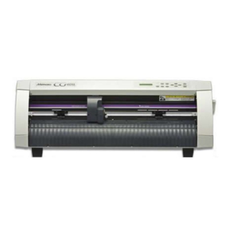
Summary of Contents for MIMAKI CG-60EX
- Page 1 CUTTING PLOTTER CG-EX Series OPERATION MANUAL MIMAKI ENGINEERING CO., LTD. TKB Gotenyama Building, 5-9-41, Kitashinagawa, Shinagawa-ku, Tokyo 141-0001, Japan Phone: +81-3-5420-8671 Fax: +81-3-5420-8687 URL: http: // www.mimaki. co. jp D200370...
- Page 3 FOREWORD Thank you for purchasing a MIMAKI “CG-EX Series” model of cutting plotter. This operation Manual describes how to handle and operate the “CG-60EX/100EX/130EX” model of cutting plotter (hereinafter called the “Device”). Please read and fully understand this Operation Manual before putting the machine into service.
-
Page 4: Precautions
PRECAUTIONS Be sure to follow the below-stated precautions when using the device. Safety precautions Thoroughly read this Operation Manual to avoid danger. Be sure to carefully read this Operation Manual, fully understand the description and make yourself familiar to the operation of the device so as to ensure safe use of the device. Limited application The device is intended to be used for cutting sheets (PVC sheets, fluorescent sheets, reflective sheets, etc.) and plotting and pouncing on drawing paper. -
Page 5: Precautions Regarding A Setup Location
Precautions regarding a setup location Never install the device at any of the following locations. The locations can adversely affect the device, impairing the cut quality or giving rise to failures. A place exposed to direct sunlight A place in which temperature and humidity vary by a great margin Operating environment: 5 to 35˚C 35 to 75% (Rh) With no dew condensation... -
Page 6: How To Use The Operation Manual
HOW TO USE THE OPERATION MANUAL About this Operation Manual Signs and symbols For the purpose of this Operation Manual, the below-stated signs are attached to important items and helpful descriptions to be remembered to prevent possible accidents and troubles and to make the most out of the device. -
Page 7: Structure Of This Operation Manual
Structure of this Operation Manual Chapter 1 Set-up This chapter describes the configuration of the accessories and main unit of the device, the procedures to be taken to set up the device and the procedures to be taken to con- nect the cables. -
Page 8: Table Of Contents
Structure of this Operation Manual..............v CHAPTER 1 SET-UP ..............1. 1 Checking the accessories ................1. 2 CONFIGURATION OF THE MAIN UNIT (CG-60EX) ........1. 4 Front of the main unit ..................1. 4 Rear of the main unit ..................1. 4 CONFIGURATION OF THE MAIN UNIT (CG-100EX/130EX) ..... - Page 9 Travel range of pinch rollers 1 and 2 ............2. 15 Selecting the clamp force ................2. 17 Loading a leaf sheet ..................2. 18 Loading a roll sheet (CG-60EX) ..............2. 19 Loading a roll sheet (CG-100EX, 130EX) ........... 2. 21 Sheet detection ....................2. 24 STARTING CUTTING (PLOTTING) ...............
- Page 10 Tool lifting speed setting [UP SPEED] ............3. 27 Change-over of jog steps [JOG STEP] ............3. 27 Dummy cut [DUMMY CUT] ..............3. 28 Mark detecting function [MARK DETECT] ..........3. 29 Sorting [SORTING] ..................3. 37 mm/inch [MM/INCH] .................. 3. 40 Sheet setting [SHEET SET] ................
-
Page 11: Chapter 1 Set-Up
CHAPTER SET-UP This chapter provides basic knowledge such as configuration that you should have in prior to the use of the device as well as a method to assemble parts and that to connect cables. – 1.1 –... -
Page 12: Checking The Accessories
Stand (CG-100EX/130EX) (CG-100EX/130EX) Turn-back lever Sheet set ring Roll bar assy. (CG-100EX/130EX) Q’ty Product name Remarks CG-60EX CG-100EX, 130EX Main unit Cutter holder 1 (E-1, E-2) 1 (E-1, E-2) Provided with blade Water-ink ball-point pen Black Stand stay Stand assy. - Page 13 Remarks CG-60EX CG-100EX, 130EX Hexagonal wrench key Power cable Grounding adapter M8 bolt CG-60EX: For mounting roll hangers CG-100EX, 130EX: For mounting stands and stay Wing bolt For mounting roll stays Rubber cap Operation manual FineCut LE – 1.3 –...
-
Page 14: Configuration Of The Main Unit (Cg-60Ex)
CONFIGURATION OF THE MAIN UNIT (CG-60EX) Front of the main unit Rear of the main unit 1) Tray Small articles can be placed on it. Note that the cutter has to be kept out of reach of children since it can be dangerous. - Page 15 6) Power switch It turn on/off the power. 7) Sheet sensor It detects the presence of the sheet and sheet length. 8) Pen line rubber The device performs cutting or plotting on the pen line rubber. 9) Pen line sponge The device performs pouncing on the pen line sponge.
-
Page 16: Configuration Of The Main Unit (Cg-100Ex/130Ex)
CONFIGURATION OF THE MAIN UNIT (CG-100EX/130EX) Front of the main unit Rear of the main unit 1) Tray Small articles can be placed on it. Note that the cutter has to be kept out of reach of children since it can be dangerous. 2) Operation panel The device is operated and functions are set on the operation panel. - Page 17 4) AC inlet The power cable is connected to the AC inlet. 5) Power switch It turn on/off the power. 6) Carriage The carriage travels from side to side while holding a tool. It is also used to raise/lower the tool. 7) Pen line rubber The device performs cutting or plotting on the pen line rubber.
-
Page 18: Attaching The Roll Hangers (Cg-60Ex)
ATTACHING THE ROLL HANGERS (CG-60EX) Mount the roll hangers following the procedures described below. 1) Fit the right-hand roll hanger to the main unit. Align the projection of the roll hanger with the corresponding hole in the main unit. Secure the roll hanger on the side plate with a hexagon head bolt using a hexagon wrench key supplied with the unit. -
Page 19: Assembling The Main Unit And Stands (Cg-100Ex, 130Ex)
ASSEMBLING THE MAIN UNIT AND STANDS (CG-100EX, 130EX) Attach the roll stays to the stands. The roll stay can be mounted to stand on the front or rear face of the main unit. Mount the roll stays to either stand according to your work. * The main unit is heavy in weight. - Page 20 4) Fix the main unit on the stands. Using the hexagon wrench key supplied with Rubber cap the unit, secure the main unit on the stands with two M8 cap bolts. After tightening the bolts, attach rubber caps onto them. 5) Securely tighten the bolts that are used to temporarily fix the stand stay onto the stands.
-
Page 21: Attached The Roll Stays To The Stands
Attached the roll stays to the stands Roll stays can be attached either (both ) front or backside. Three different heights are available. 1. When the roll stays are attached on the backside, Attached the roll stopper with the set stopper on the right side. 2. -
Page 22: Connecting The Cables
CONNECTING THE CABLES * When connecting the cables, turn off first the power to the device and that to the host computer which the power cable is to be connected. Connecting the interface cables The device comes with two different kinds of interfaces. Select either one that matches the host computer. -
Page 23: Chapter 2 Basic Operations And Setups
CHAPTER BASIC OPERATIONS AND SETUPS This chapter describes a series of operations to be carried out from the loading of tools and sheets to the actual cutting (plotting) and related operation setups along the basic operation flow. – 2.1 –... -
Page 24: Operation Panel
OPERATION PANEL Configuration of the operation panel is as shown below. 1) Display panel The display panel indicates tool conditions such as speed, pressure and offset, tool coordinates, functions and error messages. 2) POWER lamp It lights up when the power to the device is turned on. Data clear key This key is used to clear the data received. -
Page 25: Jog Keys
Jog keys The arrow keys are used as described in the table below. When inputting a Before the detection After the detection When selecting a choice selected among of a sheet of a sheet function several alternatives Detects the sheet width Shifts and carriage to the and the top end of the left. -
Page 26: Basic Operation Of The Keys
BASIC OPERATION OF THE KEYS Basic operation of the keys mounted on the operation panel is described below. Changing the operation mode Refer to page 2.9 for the explanation of operation modes. Press the key to change over the operation mode between the remote mode and local mode. Remote mode CUT1 ** REMOTE ** Local mode... - Page 27 Selecting the setup item from the function menu Select [SET UP] from the function menu following the above-stated procedure. Press the key or key to call the setup items. FUNCTION ENTER Pressing the key will select the setup item currently displayed. HOLD Refer to Chapter 3 for the types of setup items.
- Page 28 Input numeric values for the number of copies, etc. FUNCTION ENTER HOLD No. COPIES <ENT> No. COPIES No. COPIES : 10 ENTER HOLD 1/10 Enter “valid” or “invalid” of the setting. Every press on key will alternately display “ON” or “OFF.” FUNCTION ENTER HOLD...
-
Page 29: Basic Procedure For Operating The Device
BASIC PROCEDURE FOR OPERATING THE DEVICE After the completion of assembly of the main unit and connection of the cables, operate the device referring to the below-stated flow. Turning the power on P. 2.8 ---> Attaching a tool P. 2.10 --->... -
Page 30: Turning The Power On
TURNING THE POWER ON * Be sure to check to ascertain that the pinch rollers have been raised before turning the power on. * Turn on the power switch of the device after turning on the power to the host computer. -
Page 31: Operation Modes
Operation modes The device operates under three different operation modes as shown below. Sheet detection The power Not ready Remote Local mode is turned on. mode mode Raise the lever. Raise the lever. Not-ready mode When the power is turned on, the device enters the not-ready mode and stays there until a sheet of REMOTE AUTO media is detected. -
Page 32: Attaching A Tool
ATTACHING A TOOL The below-stated tools can be used with the device. Cutter, pen (water-ink ball-point pen) supplied with the unit, and pouncing tool (optional) To use the cutter, adjust the blade tip of the cutter in prior to attaching it. •... -
Page 33: Attaching A Tool
Attaching a tool Attach a tool to the tool holder of the carriage. The tool can be loaded this side or far side of the tool holder. Determine the mounting location according to your work. Far side holder This side holder Far side holder Pen-plotting or cutting of PVC sheet on the pen line rubber is enabled. -
Page 34: Tool Conditions Setting
TOOL CONDITIONS SETTING Three different tool conditions are to be set such as cutting conditions, plotting conditions and pouncing conditions. Specify “SPEED,” “PRESSURE” and “OFFSET” settings that suit the tool to be used. TOOL To set tool conditions, press the key under the local mode, select tool condition with SELECT ENTER... - Page 35 • SPEED : Cutting (plotting) speed. • PRESSURE : Pressure with which the tool hold the sheet of media. • OFFSET : The amount of the cutter blade tip from the holder. If the offset amount is increased, square-shaped characters will be cut/plotted. If it is decreased, round-edged characters will be finished.
-
Page 36: Loading A Sheet Of Media
The table given below shows the width of sheet that can be loaded on the device and the maximum cutting area of the device. Sheet width Model name inch CG-60EX 110 to 624 CG-100EX 110 to 711 755 to 912... -
Page 37: Pinch Rollers And Grid Rollers
* Never set the pinch rollers with deviated or separated from the grid rollers. If the pinch rollers are not properly placed, they may fail to retain the sheet during cutting (plotting). Pinch roller Grid roller Travel range of pinch rollers 1 and 2 CG-60EX 427~604 243~400 90~247 Grid roller Pinch roller... - Page 38 * For CG-100EX and -130EX, move the pinch roller 3 to the retracted point located at the leftmost end of its travel range in the case where the pinch roller 3 is not used for operation. If the pinch roller 3 is located at any position other the retracted point, the device will not be able to perform the sheet detection.
-
Page 39: Selecting The Clamp Force
Selecting the clamp force The clamp force of the sheet clamp can be changed in two levels using the clamp lever. Select higher or lower level of the clamp force that matches the sheet to be used. * Set the clamp force of the left and right sheet clamps equally. If the clamp pressure is not set to an equal level, the sheet could deviate from the correct position. -
Page 40: Loading A Leaf Sheet
Loading a leaf sheet 1) Pass a leaf sheet under the platen. Tilt the set lever toward you, raise the pinch rollers and adjust the rightmost end of the leaf of sheet to the scales mounted on the front and rear of the device. -
Page 41: Loading A Roll Sheet (Cg-60Ex)
Loading a roll sheet (CG-60EX) In the case where a roll sheet is used, roll hanger to be mounted on the device. Refer to page 1.18 for how to mount the roll hanger. 1) Attach the roll bar assembly to the roll hangers. - Page 42 4) The display shown on the LCD changes. ROLL < R > LEAF Press the key to select “ROLL.” The device performs the sheet detection (see ROLL LEAF page 2.24), then performs a dummy cut (see page 3.28). Displays the detected size of the leaf sheet. The display panel gives the indication as shown on the left.
-
Page 43: Loading A Roll Sheet (Cg-100Ex, 130Ex)
Loading a roll sheet (CG-100EX, 130EX) In the case where a roll of sheet is used, roll stays are required to be mounted on the device. Refer to page 1.10 for how to mount the roll stays. 1) Attach the roll bar assembly to the roll stays. - Page 44 4) Hold a sheet. Draw the sheet to tense it. Tilt the sheet set lever away from you. • In the case where the power to the device has been turned on: The suction fan will rotate to adhere the rolled sheet by suction. •...
- Page 45 7) Secure the roll sheet with the sheet set rings. Move the respective sheet set rings to the rightmost and leftmost ends of the roll sheet and fix them by tightening screws to secure the roll. 8) Draw out the rolled sheet by the length to be used.
-
Page 46: Sheet Detection
Sheet detection The width and length of the sheet is detected by pressing the arrow keys or key in accordance with the sheet loaded. * Once the length of a sheet of media has been detected, if the received data is larger than the sheet, only the portion of data that exceeds the sheet will not be cut. - Page 47 The device detects a sheet of media in the five different methods as shown below. A roll sheet is A leaf sheet is Only the sheet loaded to the rear loaded to the rear width is face of the device. face of the device.
-
Page 48: Starting Cutting (Plotting)
STARTING CUTTING (PLOTTING) After the completion of loading of a tool and sheet and establishment of tool conditions, you can start cutting (plotting). • Check up the following settings before executing cutting (plotting). Setting of the origin (see page 2.26) Priority of commands (see page 3.24) Setting of communication conditions (see page 3.18) Setting an origin... -
Page 49: Starting Cutting (Plotting)
Starting cutting (plotting) 3) After the set of the origin, press the CUT1 REMOTE REMOTE key. LOCAL The display on the LCD will change over to the remote mode. 4) Send data from the host computer to CUT1 1356KB the device. Once the device receives data, the device will give the remaining amount of data while When selecting the cutter... - Page 50 – 2.28 –...
-
Page 51: Chapter 3 Explanation Of Functions
CHAPTER EXPLANATION OF FUNCTIONS This chapter explains types and settings of functions provided by the device. – 3.1 –... -
Page 52: Listing Of Functions
LISTING OF FUNCTIONS The device is provided with the following functions. Refer to chapter 3 for how to select and enter the functions. Functions invoked with the jog keys (arrow keys) The jog function is used to move the top end of a tool to a given location to set coordinates of the plotter. - Page 53 Setting function The setting feature is used to set to adapt the function to the specifications of host computer and specify operations of the plotter. The settings are stored in memory even when the power is turned off. Item to be set Explanation of function INTERFACE Establishes communication conditions in accordance with the host computer in the...
-
Page 54: Operation Of Keys Corresponding To The Functions
Operation of keys corresponding to the functions Functions are selected and entered by operating the corresponding keys as described below. Functions invoked with specific keys Local mode CUT1 20 050 0.30 Data clear DATA ENTER REMOTE DATA CLEAR <ENT> CLEAR HOLD LOCAL Remote mode... - Page 55 Jog function Local mode CUT1 20 050 0.30 Move the carriage to the left. Move the Sheet to the far side. Move the Sheet to the this side. Move the carriage to the right. TOOL Raise/lowers the pen while the carrtage is travelling. SELECT Jog mode Origin setting...
- Page 56 Function Local mode CUT1 20 050 0.30 No. copies ENTER ENTER FUNCTION No. COPIES <ENT> HOLD HOLD Number Square cut FUNCTION of copies (test cutting ) ENTER SQUARE CUT <ENT> HOLD FUNCTION Dist. comp. ENTER ENTER DIST. COMP <ENT> HOLD HOLD Reference FUNCTION...
- Page 57 Setting Function Set up SET UP <ENT> Interface ENTER ENTER BAUD RATE :9600 INTERFACE <ent> HOLD HOLD BAUD RATE/DATA ADJ./PARITY/STOP BITS/ Cut mode HANDSHAKE/STEP SIZE/PARALLEL I/F ENTER CUT MODE <ent> ENTER CUT MODE :NORMAL HOLD HOLD NORMAL/QUALITY/HIGHspd Origin select ENTER ORGN SELECT <ent>...
-
Page 58: Explanation Of Functions
EXPLANATION OF FUNCTIONS Settings of the functions and detailed explanation of the functions are described below. Cutting area An area in which the device performs cutting (plotting) is specified. The area that has a diagonal line extending from the origin and a given UL (upper left) point is the effective cutting area. -
Page 59: Paper Cut
Paper cut The sheet is cut off at the current location of the tool. To perform the paper cutting, set the tool condition to “HALF.” The device will conduct paper cutting with the pressure specified in the tool conditions. For the paper cutting, the sheet will be cut up to the location 15 mm outside each of the pinch rollers. -
Page 60: Data Clear
Data clear The device terminates cutting (plotting) of the current data, and starts cutting (plotting) of new data. If you want to stop cutting (plotting) of the current data before the device completes it, you have to clear the data received. •... -
Page 61: Hold
Hold In the case where the sheet slips out of position during cutting (plotting) of long-distance data, the hold function is used to put the device on hold to allow the operator to correct the displacement of the sheet and re-start the operation after the completion of correction. A press on the key during cutting (plotting) will put the device on hold. - Page 62 • Reference value Cutting conditions and broken-line cutting conditions for the case where the sheet that weighs 65 kg is cut are as follows: <Cutting conditions> <Broken-line cutting conditions> • SPEED 40 cm/s • Half cut press • PRESSURE 40 g •...
-
Page 63: No. Of Copies [No. Copies]
No. of copies [No. COPIES] This function is used to perform cutting (plotting) of the received data on two or more sheets. The device stores the received data in the receiver buffer to enable cutting (plotting) in repetition on as many as 999 sheets. When the device receives new data, the data stored in the receiver buffer will be updated. -
Page 64: Test Cutting [Square]
Test cutting [SQUARE] In the case where you have changed the type of sheet or tool and cutting conditions have been changed correspondingly, the test cutting function is used to execute test cutting to check that the cutting conditions such as SPEED, PRESSURE and OFFSET are appropriate. In the test cutting, the device cuts two different types of squares. - Page 65 If no distance compensation has been 1. 000 1. 000 performed, the minimum reference length will appear on the LCD. A=500 B=200 • The length display shown below means that the [DIST. COMP] was executed using the mark detecting function or the [DIST. COMP] was changed over to the [MM/INCH].
- Page 66 6) Upon completion of plotting, the device A=0. 0 B=0. 0 will give the current compensation value on the LCD. 7) Measure the ON line along A- and B- A=1. 0 B=0. 0 axis. If any of the measurements of the ON lines A=1.
-
Page 67: Sample Cut [Sample Cut]
Sample cut [SAMPLE CUT] In the case where the device fails to cut data correctly or the end point of cutting of a character fails to meet the starting point, the cause of such a fault can be checked up by cutting the characters “Cut.”... -
Page 68: Display
DISPLAY This function is used to change over the language used to give displays on the LCD. Setting value • Japanese • English • German • French • Spanish • Italian • Portuguese Setting communication conditions [INTERFACE] This function is used to establish communication conditions of the RS-232C interface. Settings of the communication conditions differ with the command (AUTO, MGL-I c1 or MGL-II c) specified using the command change-over function. -
Page 69: Change-Over Of Cut Mode [Cut Mode]
Guide for the case where the operating procedure of the 8-bit parallel interface is set to [BUFFER]: In the case where the host computer offers high-speed data transfer and it is desired to reduce • the time of the host computer occupied by data transfer In the case where the device performs cutting intermittently since it receives data and performs •... -
Page 70: Rotation [Rotation]
Rotation [ROTATION] This function is used to specify the location of origin and direction of the axis of coordinates according to the application software to be used. Setting value (Make a choice and input it) : The device rotates the coordinate axis and relocates the origin at a time. OFF : The device does not perform rotation of the coordinate axis. -
Page 71: Division Cut [Division Cut]
Division cut [DIVISION CUT] In the case where the data on cutting exceeds the sheet width, the device is able to cut the data with divided appropriately. While the device is engaged in division cut, it will ignore other data sent from the host computer. - Page 72 • In any of the following case, the device will cut neither the frame nor the adhesion allowance marks. a) Where the capacity of data is larger than the receiver buffer capacity b) Where the origin updating command is contained in the data on cutting c) Where the two-point correcting function is specified d) Where the width of effective cutting area is 1 cm or less e) Where the device cuts the test data stored in it...
- Page 73 5) Establish a new origin. Move on the sheet using the jog key (arrow key) to establish an origin. If the sheet has no space for cutting, replace the sheet with a new one. REMOTE 6) Press the key to set the device in LOCAL the remote mode.
-
Page 74: Pouncing [Pouncing]
POUNCING [POUNCING] Pouncing is a perforated pattern. The pattern is as described below; Standard cutting Pouncing • To use special pouncing tool In order to create perforated pattern, pin (pouncing tool) and paper must be used. Setting value (Make a choice and input it) OFF : The pouncing function is rendered ineffective. -
Page 75: Remote Display [Remote Disp]
Setting value (Make a choice and input it) PANEL : The device operates using the setting established on its operation panel. HOST : The device operates using the setting established by the command setting function of the host computer. Remote display [REMOTE DISP] This function is used to specify the display to be shown on the LCD panel under the remote mode. -
Page 76: Sheet Sensor [Sheetsensor]
Sheet sensor [SHEETsensor] The sheet sensor detects the presence/absence of a sheet and the sheet length. Two sheet sensors are mounted on the platen. Sheet sensor In the case where any of the following types of sheet is used, the sheet sensors will not be able to detect it to give the error message shown below. -
Page 77: Tool Lifting Speed Setting [Up Speed]
Tool lifting speed setting [UP SPEED] This function is used to establish a traveling speed of the sheet and carriage to be employed when the tool placed in the carriage is in the raised position. If a lower speed is specified, displacement of the sheet will be eliminated at the time of long- distance feed. -
Page 78: Dummy Cut [Dummy Cut]
Dummy cut [DUMMY CUT] With this function, the device operates in such a way as to orient the blade tip to a predetermined direction when starting cutting. Execute dummy cut when you have taken the following procedure. • When selecting a tool (CUT1, CUT2, CUT3 or HALF) •... -
Page 79: Mark Detecting Function [Mark Detect]
Mark detecting function [MARK DETECT] This function is used to automatically detect a registration mark. Correct the inclination of the sheet loaded on the device, origin of plotting and distance between registration marks. Then, cut the contour of a picture pattern printed on a seal. The following types of the registration marks are to be read. - Page 80 Detecting a registration mark on a sheet The printed seal (hereinafter referred to as the “sheet”) are required to be printed with marks that satisfy the following requirements to allow the device to detect the registration mark as well as the length of A- and B-axis.
- Page 81 TYPE2 30 mm or more from 40 mm or more from the sheet backend the sheet backend A: 50 - 2000 mm Printable, cuttable range Pinch roller Set the pinch roller away from the marks. 20 mm or more from the sheet B: 50 mm or more Operation settings for detection of marks...
- Page 82 Function Setting Description Size 4-20mm Setting the detection offset of the registration marks. sensoring I t i s s e t t h e o f f s e t o f t h e detection. registration mark (TP1) A f t e r d e t e c t i n g l i n e 1 , s e t v a l u e / 2 w i l l b e t r a v e l e d t o detect line 2.
- Page 83 * If the sheet is curling up, straighten the sheet. * Use a sheet which has neither stains nor images in the area (A) located between TP1 and TP2 and in the area (B) located between TP1 and TP3. Full-automatic detection of marks It enables to compensate the difference in length of the registration marks between printed length and detected length (A and B).
- Page 84 3) Taking care not to allow the sheet to slip ROLL < R > LEAF out of position, turn the sheet set lever toward you. Then, the pinch rollers will retain the sheet. ** MARK DETECT ** 4) Press the key.
- Page 85 7) Set the origin. ORIGIN * * A = *** . * B = *** . * CUT1 20 050 0. 30 Semi-automatic registration marks detection In the case where mark 1 (TP1) is not located at the rightmost end of the sheet and cannot be laid out at the predetermined position described earlier, detect marks under the semi-automatic mode.
- Page 86 4) After the registration marks are de- A = *** . * B = *** . * tected, length (A) provided between TP1 and TP2 will be shown on the LCD. As with the case where the full-automatic detection is performed, if the length A shown on the LCD is different from that contained in the data, input the latter using the key and press the...
-
Page 87: Sorting [Sorting]
Sorting [SORTING] The sorting function is used to re-arrange the pieces of cutting data transmitted from the host computer to change the order of cutting. Pieces of data to be transmitted to the plotter by application will be arranged in the order in which they are created or edited. If data read through a scanner is modified, the modified portion of data will be placed at the end of data. - Page 88 With no area specified With area specified Cutting order Cutting order Specified area Sorting sequence 1. Data are being transmitted. Unprocessed data size in the receiving buffer is dis- CUT1 ** 2KB** played. Cutting is not conducted. The processed line segments are stored in the sorting buffer.
- Page 89 4. Cutting starts. Data that has been already cut is displayed in percents. *SORTING* 5. Cutting completes. The plotter enters the remote mode. CUT1 **REMOTE ** • When the SORTING is set to the ON state, cutting will not start until the specified close time has elapsed after receiving all pieces of data to be cut.
-
Page 90: Mm/Inch [Mm/Inch]
6. The operation returns to Step 2. SORTING <ent> * The settings established will be stored in memory even when the power of the device is turned off. * Changing the setting will clear data that is stored in the receiving buffer. * When the sorting is set to the ON state, the receiving buffer size will be decreased to 1 MB. -
Page 91: Sheet Setting [Sheet Set]
Sheet setting [SHEET SET] In the case where a heavy sheet or wide sheet is to be used, the sheet setting is performed using the sheet setting function to avoid displacement of the sheet. In the case where the [SHEET SET] is set to “HEAVY,” the maximum speed that can be specified will be 20 cm/s and the acceleration will be a half of the normal value. - Page 92 – 3.42 –...
-
Page 93: Chapter 4 In Case Of Trouble
CHAPTER IN CASE OF TROUBLE This chapter describes items to be checked in the event that abnormal conditions are encountered and remedies to be taken in the event that an error message appears on the LCD. – 4.1 –... -
Page 94: Before Taking A Phenomenon As A Trouble
BEFORE TAKING A PHENOMENON AS A TROUBLE Take appropriate remedies referring to the phenomena described below. The device cannot detect a sheet. [** NO SHEET **] Cause 1 : A transparent sheet or a sheet of which wrong side is black is used. Remedy 1 : Set the sheet sensor function to OFF. - Page 95 Remedy 5-1 : Decrease the cutting speed (SPEED) to reduce the load to the sheet when it contacts the floor surface. Remedy 5-2 : If you use CG-60EX, use the optional stand or any stand that is equivalent to the optional one.
-
Page 96: Trouble For Which Error Messages Are Given On The Lcd
TROUBLE FOR WHICH ERROR MESSAGES ARE GIVEN ON THE LCD If something is wrong with the device, a corresponding error message is given on the LCD. Take an appropriate corrective measure according to the remedies given in the table below. Error message Cause Action... - Page 97 Error message Cause Action ERR30 OPERATION An inappropriate operation was Perform the correct operation. performed on the control panel. ERR31 NO DATA The device has executed the plural Refer to the explanation of the plural sheets cutting to find that there is no sheets cutting function.
-
Page 98: Displays Under The Remote Mode
Displays under the remote mode The messages given below appear under the remote mode. They do not indicate errors but require an appropriate action. Message Cause Action CUT1 * REMOTE * The device is in the remote mode. A press on the key will cause the device to enter the local mode. - Page 99 Message Cause Action * DIVISION * 5s The device has finished the cutting If the device does not receive any of data that exceeds the sheet width data from the host computer within using the division cut and is now ten seconds, it will recognize the waiting for the receipt of data has ended.
- Page 100 – 4.8 –...
-
Page 101: Appendix
APPENDIX The appendix describes the replacement of blades, output samples and specifications of the main unit of the device. – A.1 –... -
Page 102: Cutter Blade
If the cutter blade is chipped or blunt, replace it with a new one. New blades (low-pressure blade set for PVC sheet: Model SPB-0030) are available from your distributor MIMAKI sales office. Replacing the blade of the cutter supplied with the unit as an accessory... -
Page 103: Adjusting The Cutter Blade
Adjusting the cutter blade Adjustment of the blade of any cutter other than that supplied with the unit is described below. After the completion of adjustment, be sure to set cutting conditions and perform test cutting to check the blade for sharpness. Refer to page 2.11 for how to adjust the cutter blade supplied with the unit. -
Page 104: Sample Of Output
SAMPLE OF OUTPUT Dump list 8 bit parallel interface RS-232C interface – A.4 –... -
Page 105: List
List – A.5 –... -
Page 106: Specifications Of The Main Unit
SPECIFICATIONS OF THE MAIN UNIT Item CG-60EX CG-100EX CG-130EX Acceptable sheet width inch inch inch 100~624 110 ~ 711 110 ~ 711 755 ~ 912 755 ~ 1070 36, 36, 42 871 ~ 1028 36, 42 1167 ~ 1324 48, 50, 52... - Page 107 Plotter conditions • The exclusive stands shall be used (for CG-60EX, the exclusive optional stands or equivalent shall be used). • Exclusive roll bars and sheet set rings (when a roll sheet is used) shall be used. • The clamp pressure shall be set to “HIGH.”...
- Page 108 D200370-1.20-14042003 – A.8 –...
- Page 110 Printed in Japan D200370 © MIMAKI ENGINEERING CO., LTD.
Need help?
Do you have a question about the CG-60EX and is the answer not in the manual?
Questions and answers