
Related Manuals for MIMAKI CFX Series


Summary of Contents for MIMAKI CFX Series
- Page 1 Download the latest version of the operation manual from our website. MIMAKI ENGINEERING CO., LTD. D203687-12 Original instructions...
-
Page 2: Table Of Contents
Table of Contents CAUTION ..................vi DISCLAIMERS ..................vi TV and Radio Interference ..............vi Usage Restrictions ................vi Introduction ..................ix About This Operation Manual .............. ix Accessories ..................ix Safety Precautions ................x Symbols ....................x Warning Labels ................xiii Chapter 1 Setup Installation .................. - Page 3 Mounting Tools (Standard Unit) ...........2-4 Pen ....................2-4 Mounting a Pen Adapter ..............2-5 Swivel cutter (optional) ..............2-8 Mounting Tools (Tangential Unit) ..........2-10 Tangential Unit (TUT) Structure ............2-10 Mounting the Tangential Unit ............2-11 Mounting the Flat Blade Tool ............2-14 Mounting a Reciprocating Cutter .............2-17 Mounting a Creasing Roller .............2-22 Mounting a V-cut Tool ..............2-24 Mounting Tools (Router Unit) .............2-32...
- Page 4 Chapter 4 Helpful Tips Function Setting List ..............4-2 Jog Mode Functions ..............4-4 2-point Axis Correction ..............4-5 Cutting Area Settings ................4-6 Moving the Head to a Corner of the Cutting Area ......4-7 Manual Cutting ..................4-8 Aligning the Pointer Position .............4-9 Assigning Pen Numbers ............
- Page 5 Chapter 5 Register Mark Reading Functions Precautions When Preparing Data with Register Marks ....5-2 Register Mark Size ................5-2 Supported Arrangements of Register Marks and Patterns ....5-3 No-Drawing Areas Around Register Marks ........5-5 Register Mark Color ................5-7 Blurry or Smudged Register Marks ...........5-8 Setting Mark Detection Operation ..........5-9 Precautions on Mark Detection ............5-9 Setting Mark Detection Operation ...........5-10...
- Page 6 OPT-C0249 5.5 kw / 6.3 kw Vacuum Unit Assy......8-12 OPT-C0252 Camera Unit - CAMERA ..........8-13 OPT-C0251 Router Unit: 1 kW - R10 ..........8-14 Supplies ..................8-15 Tools ....................8-15 Supplies ...................8-17 Marker Pens Compatible with the CFX Series ......8-24 License Library (EPL5 StarterWare) .......... 8-25...
-
Page 7: Caution
COVERED BY THE PRODUCT WARRANTY. MIMAKI ENGINEERING REJECTS ALL LIABILITY FOR DAMAGE, DIRECT OR INDIRECT, ARISING FROM SUCH INCIDENTS. • USE ONLY GENUINE MIMAKI ENGINEERING TOOLS AND PARTS. USE OF OTHER PRODUCTS MAY RESULT IN FAILURES OR REDUCE CUT QUALITY. SUCH INCIDENTS ARE NOT COVERED BY THE PRODUCT WARRANTY. - Page 8 CFX-2513 1000 mm or more 1000 mm 1000 mm or more or more 1000 mm or more 6050 mm or more CFX-2531 1000 mm or more 1000 mm 1000 mm or more or more 1000 mm or more 6050 mm or more...
- Page 9 CAUTION CFX-2550 1000 mm or more 1000 mm 1000 mm or more or more 1000 mm or more 6050 mm or more viii...
-
Page 10: Introduction
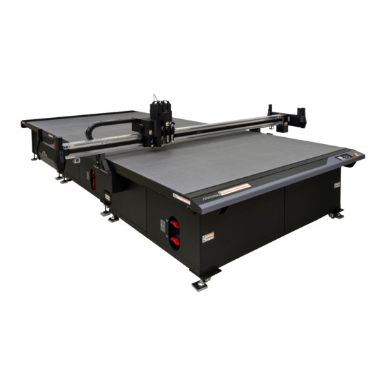
About This Operation Manual • This manual describes the operation, maintenance, and other handling of CFX Series flatbed cutting plotters (“the machine”). • Read this manual carefully and make sure you understand it before use. Keep the manual in a convenient place for reference as needed. -
Page 11: Safety Precautions
Safety Precautions Symbols In this manual, symbols indicate and explain precautions. The indicated symbol varies depending on the nature of the precaution. Make sure you understand the meaning of each symbol and use the machine safely and correctly. Examples of symbols Explanation Failure to observe the instructions given with the [Warning] symbol may result in death or serious injuries to personnel. - Page 12 Warning Do not disassemble or modify Handling of cables • Never disassemble or modify plotter main unit • Do not attempt to modify power or or vacuum unit. Disassembling or modifying communication cables, and avoid damaging or will result either in electric shock or malfunction breaking them.
- Page 13 Do not work while wearing baggy clothing or jewelry Contact Mimaki before moving the plotter to another location • Do not wear baggy clothes or fashion • Plotters are precision instruments. Contact accessories while working.
-
Page 14: Warning Labels
Warning Labels Warning labels have been applied to the machine. Make sure you fully understand the details indicated on the various warning labels. If a warning label is illegible due to stains or has come off, purchase a new one from a dealer or our service office. - Page 15 Warning Labels Optional accessories ③ ③ ③ ② Tangential High-pressure Router unit Router unit unit (TUT-15) tangential (R10) electrical box unit (TUT-30)
- Page 16 No. Order code Label Details PL label Be careful around moving parts. M902667 Failure to observe these instructions may result in injury. Hazardous high voltage M907935 inside. Be careful around the M905694 blade. Advises cautions regarding tool M915343 installation. Keep fingers and body M909381 away from moving parts to avoid injury.
- Page 17 Warning Labels Prohibits putting feet on the indicated M909385 place. Be sure to ground the machine, in M905624 consideration of the high leakage current. Standby label M918881 Take safety measures when M915322 working with flammable materials. *1. Included with purchase of R10 option.
- Page 18 xvii...
-
Page 19: Setup
Chapter 1 Setup About this chapter This chapter describes information essential before use, such as part names. Installation............. 1-2 Setting the Vacuum........1-20 Vacuum (Optional) Installation Position ..1-2 Enabling/Disabling Auto Vacuum Off ..1-20 Moving the Machine ........1-2 Interlock between Remote Key and Part Names and Functions ...... -
Page 20: Installation
Installation Install the machine in a location where the following installation space is available. • Keep the installation space free of other objects. These may cause you to trip. Model Width Depth Height Gross weight Vacuum units CFX-2513 4050 mm 2150 mm 1500 mm Approximately 440 kg... -
Page 21: Part Names And Functions
Part Names and Functions Main Unit (11) (10) (12) (12) Name Function Press in case of emergency. Forces the power off and stops Emergency switch operation. Detects operators or obstructions within the head range of Safety sensors motion. Holds the work. Features a regular array of small holes for Cutting panel (felt mat) vacuum adhesion. -
Page 22: Head
Head Front Name Function Station A A pen or swivel cutter is mounted on the standard unit. LED pointer Used for alignment or setting the origin for reading register marks. Mark sensor Sensor for detecting register marks. Station B Used for mounting a tangential unit. Station C Used for mounting a tangential unit. -
Page 23: Electrical Box Side
Part Names and Functions Electrical Box Side Interfaces Name Function Ethernet connector Connect a computer using a LAN cable. RS-232C interface Connect a computer using an RS-232C interface cable. Foot switch 1 port Connect a foot switch. Foot switch 2 port Connect a foot switch. -
Page 24: Vacuum Unit Electrical Box (Optional)
Vacuum Unit Electrical Box (Optional) Name Function For turning the vacuum unit on/off. Normally, leave in the on position. Power switch Switch to off for maintenance. Power supply connector Connect the vacuum power cable. Connector for control Connect to the vacuum connector on the electrical box. Head Side (When Equipped with Option/R10) Name Function... -
Page 25: Operating Panel
Part Names and Functions Operating Panel This is used to control the product and make/change settings. Local B-Unit:FBT SPD: 30.0cm/s Zof: 0.0mm UP: 4mm WT: 5.0mm A:SCT CAMERA B:FBT C:E35 D:C16 MENU REMOTE VACUUM END POWER ENTER FUNC1 FUNC2 FUNC3 Name Overview Display... -
Page 26: Display
Display Remote MENU mode <setting type number*> Selected station and tool Volume of data received 256KB B-Unit:FBT • Station A to D: Tool name SPD: 30.0cm/s Zof: 0.0mm • Tangential unit name Cut Condition UP: 4mm Data receiving status Ready WT: 5.0mm (Displayed in continuous mode only) Tool status... - Page 27 Part Names and Functions Station C Tool Reciprocat- Reciprocat- Reciprocat- Flat Crease Crease Crease Status V-cut V-cut blade roller roller roller cutter cutter cutter tool Not selected C:FBT C:E12 C:E35 C:E60 C:C16 C:C26 C:C60 C:V45 C:VAS Selected C:FBT C:E12 C:E35 C:E60 C:C16 C:C26...
- Page 28 [FUNCTION] keys This section describes the functions and roles assigned to the [FUNCTION] keys. Icon Name Displays the various menu screens. Turns vacuum operation on/off. VACUUM Used to switch from LOCAL mode to REMOTE mode screen. Displays the test cut selection screen. Displays the screen for copying elements.
-
Page 29: Cable Connections
The unit is equipped with an RS-232C compliant interface and a LAN port. Use the RS-232C interface cable recommended by Mimaki or a suitable cable for your computer. The communication conditions must be set to suit the interface used. For details, refer to “Setting Computer Connection Conditions”... -
Page 30: Emergency Stop
Emergency Stop In emergencies, the machine can be stopped on an emergency basis. Emergency switches are located at four positions at the front and rear of the machine. Using Emergency Stop Press an emergency switch. • The machine stops operating. Resetting an Emergency Stop Turn the emergency switch clockwise to unlock Press the [ENTER] key. - Page 31 Emergency Stop • If any unit from B to D remains lowered after resetting, a confirmation message is displayed. Confirm that there will be no problem if the tool is raised, and then press the [ENTER] key. B-Unit After remove obstacle •...
-
Page 32: Preparing The Cutting Panel
Preparing the Cutting Panel Attaching the Work Guides Attach the work guides as guides to keep works straight. Attach guides to suit the work size, at the position desired. • Make sure the work guides are securely attached in the holes on the cutting panel surface. The head may come into contact with loose work guides that are not attached securely when the machine is turned on, which may cause damage. -
Page 33: Local/Remote Mode
Local/Remote Mode Each press of [LOCAL] [REMOTE] on the operating panel switches between local and remote mode. Local Mode and Corresponding Display In local mode, you can move the head, set various machine functions, and receive data from the computer. All keys are available in local mode. - Page 34 Flat Blade Tool selected (TUT) This is the remote screen when the unit SPD: Cutting speed Remote selection is B, C, or D in [Tool Select] on the Zof: Z origin offset value UP: Up height 15KB local mode screen and the Flat Blade Tool B-Unit:FBT WT: Work thickness (FBT) is selected as the tool.
- Page 35 Router unit select (R10) This is the remote screen when D-Unit is SPD: Cutting speed Remote selected in [Tool Select] on the local mode Zof: Z origin offset value UP: Up height 15KB screen and the router unit (R10) is selected as D-Unit:R10 ROT: Rpm the tool.
-
Page 36: Matching The Plotter Specifications
Matching the Plotter Specifications The machine uses MGL-3C commands. Set the commands of the software that is connected to the machine to MGL-3C. • The machine only uses MGL-3C commands. Commands cannot be changed from the plotter. 1-18... -
Page 37: Setting Automatic Head Retraction
Setting Automatic Head Retraction Set the final head position after cutting (or drawing) the data from the computer is finished. Retraction Item Setting value position (1) Off No automatic retraction. Retract to the lower right. (2) Lower right (3) Lower left Retract to the lower left. -
Page 38: Setting The Vacuum
Setting the Vacuum Enabling/Disabling Auto Vacuum Off Set vacuum auto-off operation. Item Setting value If the automatic head retraction setting is enabled, the vacuum Enable automatically turns off after the head is retracted. The vacuum remains on even after head retraction. Disable *1. -
Page 39: Interlock Between Remote Key And Vacuum
Interlock between Remote Key and Vacuum The vacuum can be turned on/off automatically using the remote key. Cutting without the vacuum on may cause works to rise and interfere with cutting. This can be prevented by setting [Vacuum Auto-On] to [Enable]. Item Setting value Vacuum is automatically turned on when remote mode is selected with... -
Page 40: Setting The Camera Unit
Setting the Camera Unit Setting instructions for a connected camera unit (optional) are as follows. Camera Unit Overview This optional unit enables mounting of a camera on the head. The following operations are available when the unit is linked to the camera app (OBSCURAS). Also refer to the OBSCURAS instruction manual. •... -
Page 41: Tools
Chapter 2 Tools About this chapter This chapter describes how to mount tools. Using a Combination of Units ....... 2-2 Mounting a Reciprocating Cutter ....2-17 Mounting a Creasing Roller ....... 2-22 Combining Stations and Units ..... 2-2 Unit and Tool Combinations ......2-2 Mounting a V-cut Tool ........ -
Page 42: Using A Combination Of Units
Using a Combination of Units This chapter describes the procedures for attaching units (standard and tangential) to each of the stations A to D, and for setting the tools. Combining Stations and Units The tangential units can be mounted on stations B, C, or D only. However, if electric reciprocating tools E12, E35, or E60 are mounted on a tangential unit, the unit can be mounted only on station B or C. - Page 43 Using a Combination of Units Standard unit (Cannot be removed) TUT-15, TUT-30 Tangential unit (optional) Router unit (optional) Camera unit (optional) (Can be mounted on station B, C, (Can only be mounted on (Can be mounted on station A) or D) station D) [10] [11]...
-
Page 44: Mounting Tools (Standard Unit)
Mounting Tools (Standard Unit) The following tools can be mounted on the standard unit • Pen • Swivel cutter (supplied) Pen adapter • This should always be left on. • Adjustment must be repeated in the following sequence if the pen adapter has been removed or mounted. This is essential if positional and dimensional accuracy is required. -
Page 45: Mounting A Pen Adapter
Mounting Tools (Standard Unit) Mounting a Pen Adapter Insert the ballpoint pen holder or swivel cutter holder in pen adapter A. Pen adapter A Attach pen adapter B. Pen adapter B Turn the station A screw to loosen the holder for the pen holder. - Page 46 Attaching caps Caps are used to protect works and tables. Remove caps in the following cases. • When using pens • When using swivel cutters • During tool adjustment • Be sure to leave caps attached when thickness measurement is automatically detected. Attach the cap from below.
- Page 47 See step 3 and later in P.2-5 “Mounting a Pen Adapter”. • • Remove the cap before use. Also refer to the following instructions. ( P.2-6) Marker pens compatible with CFX series For details, see “Marker Pens Compatible with the CFX Series” ( P.8-24).
-
Page 48: Swivel Cutter (Optional)
Swivel cutter (optional) • Handle with care to avoid injury from the blade. For safety, use the included tweezers. • The swivel cutter is suited to cutting where the adhesive sheet or base paper needs to be left behind. If the cutter blade is inserted as far as the felt surface, there is a risk of it being left inside the felt, resulting in injury or damage. - Page 49 Mounting Tools (Standard Unit) Attach the swivel cutter holder to the pen adapter and mount it on the standard unit P.2-5 “Mounting a Pen Adapter”).
-
Page 50: Mounting Tools (Tangential Unit)
Mounting Tools (Tangential Unit) Tangential Unit (TUT) Structure Any of the following tools can be mounted on the tangential unit. Reference Name Abbreviation or type page Tangential unit TUT-15, TUT-30 P.2-11 Flat Blade Tool P.2-16 Electric reciprocating tool E12, E35, E60 P.2-19 Creasing tool C16, C26, C60... -
Page 51: Mounting The Tangential Unit
Mounting Tools (Tangential Unit) Mounting the Tangential Unit For blades to mount, use only genuine Mimaki tools. Use of other tools may result in inaccurate cutting edge detection. Genuine tools are as follows. Tool Corresponding blade length 24.8 to 45 mm 28 to 65.2 mm... - Page 52 Using the included hex wrench, turn the two screws on the unit to secure in place. 2-12...
- Page 53 Mounting Tools (Tangential Unit) Removing the tangential unit Turn the main unit off. Using the included hex wrench, turn the two screws on the unit to remove it. Pull the tangential unit off the station while supporting with both hands, and slowly lift it up. •...
-
Page 54: Mounting The Flat Blade Tool
Mounting the Flat Blade Tool • Always wear safety gloves when handling tools and cutter blades. Failure to observe these instructions may result in injury from the blade. • Be sure to repeat cutting edge detection ( P.3-13) if the blade has been replaced. •... - Page 55 Mounting Tools (Tangential Unit) Using the included hex wrench (2.5 mm), Flat blade holder temporarily tighten the set screws to secure the flat blade holder to the Flat Blade Tool. • Select a holder that suits the blade you will mount. Insert the flat cutter blade into the flat cutter Tweezers blade holder until it rests firmly against it.
- Page 56 Mounting the Flat Blade Tool • Even when only the cutting blade was replaced, be sure to use [Tool Exchange] to detect the cutting blade ( P.3-13). If the procedure is not followed, there is a risk of the cutting depth changing, possibly damaging the cutter blade or equipment, or causing injury.
-
Page 57: Mounting A Reciprocating Cutter
Mounting Tools (Tangential Unit) Mounting a Reciprocating Cutter The reciprocating cutter can be mounted on the B or C station. For details, see ““Combining Stations and Units” on page 2.” • Always wear safety gloves when handling tools and cutter blades. Failure to observe these instructions may result in injury from the blade. - Page 58 Hold the cutter blade with tweezers as you temporarily tighten the screws. • Temporarily tighten the screws so that only a little pressure is applied to the spring washers of the screws. • Do not tighten the upper screws until attached to the reciprocating tool.
- Page 59 Mounting Tools (Tangential Unit) Mounting the Electric Reciprocating Tool and Reciprocating Cutter Holder • Lightly apply the grease provided before mounting the electric reciprocating tool. Apply approximately 0.05 g of grease each to the upper and lower parts. Apply to Apply steps around pin...
- Page 60 Lower the tangential unit tool lock lever and Stopper pin insert the electric reciprocating tool into the opening, all the way down. • Once it is inserted all the way down, raise the tool lock lever to secure the electric reciprocating tool. •...
- Page 61 Mounting Tools (Tangential Unit) Using the supplied hex wrench, tighten the set screw to secure the reciprocating cutter holder. Once the tool has been mounted, press the [ENTER] key. • The resetting operation starts. Perform cutting edge detection ( P.3-13).
-
Page 62: Mounting A Creasing Roller
Mounting a Creasing Roller Refer to the table below for the initial setting conditions when using the creasing tool. • If creasing is performed with an entry depth from the work surface significantly exceeding the recommended value, the creasing roller may become embedded in the media, detach from the tool holder, and damage the equipment or result in injury. - Page 63 Mounting Tools (Tangential Unit) Press the [ENTER] key. • The head moves to the right end. Once the head has stopped, mount the crease Control pin roller tool on the tangential unit from above. • Fit the control pin of the crease roller tool into the groove at the rear of the tangential unit.
-
Page 64: Mounting A V-Cut Tool
Mounting a V-cut Tool • Always wear cut-proof safety gloves when handling tools and cutter blades. Failure to observe these instructions may result in injury from the blade. • Be sure to repeat cutting edge detection ( P.3-13) if the blade has been replaced. Attaching a V-cut blade •... - Page 65 Mounting Tools (Tangential Unit) Mounting a V-cut tool • Even when only the cutting blade was replaced or the VAS tool cutting edge angle was changed, be sure to use [Tool Exchange] to detect the cutting blade ( P.3-13). If the procedure is not followed, there is a risk of the cutting depth changing, possibly damaging the cutter blade or equipment, or causing injury.
- Page 66 Lower the tangential unit tool lock lever and insert the V-cut tool into the opening, all the way down. • Once it is inserted all the way down, raise the tool lock lever to secure the V-cut tool. Tool lock lever Mount the V-cut holder on the V-cut tool from below.
- Page 67 Mounting Tools (Tangential Unit) V-cut Hold the V-cut holder still with your hand and turn tool knob the V-cut tool knob on the top of the bearing holder clockwise as viewed from above. • Turn to the position of the lock mark. •...
- Page 68 Removing the V-Cut Holder Select [Menu] > [Tool] > [Tool Exchange]. • [Move the head to the Right edge.] is displayed. (This screen does not appear if the head is already at the right end.) Press the [ENTER] key. • The head moves to the right end. Once the head has stopped, mount the V-cut cap in the V-cut holder, then turn the lever to secure the cap in place.
- Page 69 Mounting Tools (Tangential Unit) Pull down the V-cut holder to remove it. Lower the tangential unit tool lock lever, and pull up the V-cut tool. Tool lock lever Once it has been removed, press the [ENTER] key. • The resetting operation starts. 2-29...
- Page 70 Changing the blade angle (VAS only) On VAS (variable angle) V-cut holders, the angle can be changed. Depending on the angle, the mounting position varies as follows. Angle 0° 15° 22.5° 30° 45° • When mounting the VAS or changing the blade angle, use the [Tool Exchange] menu as described in Mounting a V-cut Tool ( P.2-24), and be sure to set the blade angle and perform blade detection P.3-13).
- Page 71 Mounting Tools (Tangential Unit) Using the supplied hex wrench (3mm), tighten the set screw. 2-31...
-
Page 72: Mounting Tools (Router Unit)
Mounting Tools (Router Unit) Attaching the router unit R10 • Always wear safety gloves when handling tools and end mills. Failure to observe these instructions may result in injury from the blade. Attaching the router unit • For safety, be sure to turn off the power to the main unit before this work. (Do not attempt mounting or removal when the power is on.) Turn the main unit off. - Page 73 Mounting Tools (Router Unit) Connect the two spindle cables, two air tubes, Air tubes and dust collector hose on the router unit to the Spindle cables specified locations on the side of the head. • To connect the spindle cables, turn the locks clockwise to tighten them.
- Page 74 Mount the terminal cover to station D after the Terminal cover router unit has been removed. • Secure with the retaining screw. Retaining screw 2-34...
- Page 75 Mounting Tools (Router Unit) Mounting an end mill on the spindle • Even when an end mill was replaced, be sure to use [Tool Exchange] to detect the cutting blade P.3-13). If the procedure is not followed, there is a risk of the cutting depth changing, possibly damaging the end mill or equipment, or causing injury.
- Page 76 Set the spindle on the end mill replacement stand. Place the provided 22 mm wrench on the collet nut, then rotate counterclockwise to loosen it. Tighten • Only use tools included with the machine. Failure to observe these instructions may damage the nut. Loosen •...
- Page 77 Mounting Tools (Router Unit) Push the tip of the end mill up against the stopper and tighten the collet nut by hand. Finally use a wrench to tighten fully. (Tightening torque 8 N·m) • Do not tighten without the end mill in place. This may deform the collet.
- Page 78 Once the tool has been mounted, press the [ENTER] key. • The resetting operation starts. Perform cutting edge detection ( P.3-13). 2-38...
- Page 79 Mounting Tools (Router Unit) Cleaning the collet The collet should be cleaned each time it is removed and reattached, because it easily becomes clogged with cutting debris. Referring to P.2-35 “Mounting an end mill on the spindle”, remove the collet. Clean with a compressed air gun.
-
Page 80: Mounting The Work Holder
Mounting the Work Holder The work holder prevents the work from rising up after it is cut. Mount as needed when using the flat blade tool (FBT) or electric reciprocating tool (E12, E35, E60). • Use the work holder for the following works. Holder S Holder L S (provided): FBT, E12, E35 (up to 30 mm) - Page 81 Chapter 3 Basic Operations About this chapter This chapter describes the basic operations normally used. Basic Operation Flow........3-2 Circle Θ Correction ........3-34 Turning the Power On........3-3 Test Cutting..........3-36 Checking tool status ........3-37 Moving the Head........... 3-4 Checking Status Between Tools Moving the Head with the [Move to (Standard Unit, TUT) .........
-
Page 82: Basic Operation Flow
Basic Operation Flow The basic operation workflow is as follows. For details, see the reference page for each step. Turning the Power On See “Turning the Power On” ( P.3-3). Moving the Head See “Moving the Head” ( P.3-4). Securing Works See “Securing Works”... -
Page 83: Turning The Power On
Turning the Power On The machine is equipped with two power switches. Main power supply switch: Located on the right side of the machine's electrical box. [END/POWER] key (power switch): This switch is normally used to turn the machine on and off. •... -
Page 84: Moving The Head
Moving the Head The head can be moved to a more convenient position when securing a work, making a test cut, mounting a tool, or in other situations. There are two ways to move the head. • Using the [Move to View Pos.] function •... -
Page 85: Moving The Head With The Jog Keys
Moving the Head Moving the Head with the Jog Keys Use this method when mounting tools, making test cuts, sample cuts, and in other situations. By pressing the jog keys, you can move the head to the exact position needed. The coordinates indicated are relative to the command origin. -
Page 86: Setting Underlay Thickness
Setting Underlay Thickness The underlay is a sheet placed underneath the work (between the work and the felt mat) to prevent damage to the felt mat when milling or using other machining processes. When using underlay, set the underlay thickness using the following procedure. The set work thickness will be cleared in the following cases. - Page 87 Setting Underlay Thickness Press to select [Exist], then press the [ENTER] key. • The underlay thickness setting menu is displayed. Underlay Thickness Underlay Thickness 0.4mm Automatic detection > Select [Underlay Thickness], then press the [ENTER] key. Press to enter the underlay thickness, then press the [ENTER] key. •...
-
Page 88: Securing Works
Securing Works There are two ways to secure works on the machine. • Securing works with vacuum • Securing works with adhesive tape • Maximum thickness of works that can be set up or cut varies depending on the selected tool and blade. -
Page 89: Securing Works With Vacuum
Securing Works Securing Works with Vacuum Relatively light works such as thin coated board, corrugated cardboard, or sponge can be held in place by vacuum adhesion. • If all the suction holes on the cutting panel are not covered by the work, cover all the suction holes with film or other means as shown below. - Page 90 Place the work on the cutting panel. On the local mode screen, press [VACUUM]. Switch the suction valves to suit the work. Make sure that the area used for cutting does not extend beyond the effective cutting area. • Suction valves Valve Table Opening V1...
-
Page 91: Setting Work Thickness
Setting Work Thickness Once the work is set up, set the work thickness based on the thickness of the work used. Setting work thickness The following methods are available to set work thickness. • Automatically set work thickness. “Measuring automatically” ( P.3-11) •... - Page 92 Entering values manually Check (or measure) the work thickness. Press on the local mode screen. • The [JOG Function Selects] screen is displayed. Select [JOG Function Selects] > [Work Thickness]. Select [Numerical input]. Press to enter the work thickness, then press the [ENTER] key. •...
-
Page 93: Cutting Edge Detection
Cutting Edge Detection Detects the tip position of the mounted tool. Immediately after turning the machine on, or when the height of the tip position changes after a tool is changed or for other reasons, perform cutting edge detection as follows. The following methods are available for cutting edge detection. - Page 94 Automatically detecting only specified tools Press in [Cutting Edge Detection] to select tools for detection. With [Automatic detection] selected, press the [ENTER] key. • Automatic detection only applies to your specified units. After detection is complete, press the [END/POWER] key several times to return to the local mode screen.
-
Page 95: Configuring Tool Settings
Configuring Tool Settings Selecting Tools Set the tools to be used for cutting (or drawing). On the local mode screen, press [MENU]. Local B-Unit:FBT SPD: 30.0cm/s Zof: 0.0mm UP: 4mm WT: 5.0mm CAMERA A:SCT B:FBT C:E35 D:C16 MENU VACUUM REMOTE Press to select [Tool] >... -
Page 96: Changing Cutting Conditions
Changing Cutting Conditions Before starting cutting (or drawing), select the cutting conditions to suit the work and tool used. On the local mode screen, press [MENU]. Local B-Unit:FBT SPD: 30.0cm/s Zof: 0.0mm UP: 4mm WT: 5.0mm CAMERA A:SCT B:FBT C:E35 D:C16 MENU VACUUM... -
Page 97: Setting Items
Configuring Tool Settings Setting items Setting items for cutting conditions vary by tool. Tool type Setting item Setting value Details Speed of tool movement in the X or Y Cut (draw) 0.1 to 100 (cm/s) direction. Varies by tool, work, and the size ○... - Page 98 Tool type Setting item Setting value Details Select the reciprocating cutter vibration Vibration level Low, Mid, High ○ frequency in a range of three levels. Amount of cutting start position offset when 0.00 to 2.50 (in 0.01 mm ○ ○ the tool is lowered.
- Page 99 Configuring Tool Settings Tool type Setting item Setting value Details 18000 to 40000 rpm The number of revolutions per minute for Rotation speed ○ (in 1000-unit increments) router unit rotation. Setting to raise and operate brush on the 0.0 to 10.0 mm (in 0.1 Brush offset end of the router unit dust collector nozzle ○...
- Page 100 ● Recommended cutting conditions when using the router unit Blade Rotation Cutting Thickness End mill Cutting Count cut Speed Work type diameter speed depth speed (mm) type direction (cycles) (cm/s) (mm) (1000rpm) (mm) (mm/s) Resin sheet 5 or less SPB-0067 Up cut Aluminum composite...
-
Page 101: Adjusting Tools
Adjusting Tools Tool adjustment is required in cases such as when the start and end points do not match when drawing (or cutting) with the machine. • In toggle mode, tool adjustment drawing is only possible in the front area. The following three tool adjustments are available (1) Cutter adjustment: Adjusts cutters. - Page 102 Center adjustment (tangential unit) Check test patterns drawn by a cutter or roller to correct misalignment due to eccentricity. • When adjusting the roller, the pen should be mounted on unit A in advance. Test pattern drawn by a cutter Test pattern drawn by a roller Normal pattern A Normal pattern B...
- Page 103 Adjusting Tools When the confirmation screen is displayed, press the [ENTER] key. • Cutting is executed. Press to select [Center A] or B, then press the [ENTER] key. Press , then enter a correction value. CENTER A: -5.00 mm to +5.00 mm CENTER B: -5.00 mm to +5.00 mm •...
- Page 104 How to adjust using center adjustment Eccentricity can be adjusted with the following screen displayed. CENTER A adjustment B-Unit:FBT Adjustment to align the center of the cutter (or roller) with the center of the CENTER A 0.00mm holder. CENTER B Press to adjust.
- Page 105 Adjusting Tools Offset adjustment (tangential unit) Compensate for misalignment by comparing a test pattern drawn Normal test pattern with a pen to a test pattern drawn by a cutter or other tool. • Mount the pen on unit A in advance. Cutting 30 mm On the local mode screen, press [MENU].
- Page 106 Press , then enter a correction value. OFFSET X: -20.0 mm to +20.0 mm OFFSET Y: -20.0 mm to +20.0 mm • For details, see “How to adjust using offset adjustment” on the next page. • For R10, the input screen is different. See “Performing offset adjustment (for R10)” ( P.3-28).
- Page 107 Adjusting Tools How to adjust using offset adjustment Offset adjustment is possible with the following screen displayed. Offset X adjustment B-Unit:FBT Distance from pen to cutter or other tool in the X direction. CENTER A 0.00mm Press to adjust. (0.1 mm pitch) CENTER B 0.00mm OFFSET X...
- Page 108 Performing offset adjustment (for R10) For the router unit (R10), adjust as follows. Perform steps 1 to 8 of “Offset adjustment (tangential unit)”. • A screen for entering the setting value is displayed after test pattern cutting. Press [POSITION SELECT] and set the alignment position. D-Unit: R10 •...
- Page 109 Adjusting Tools Performing theta angle adjustment Adjust the angle of rotation by comparing a test pattern drawn with a pen to a test pattern drawn by a cutter or roller. • The values in parentheses in the figure below indicate the sizes when a roller is used. •...
- Page 110 On the local mode screen, press [MENU]. Local B-Unit:FBT SPD: 30.0cm/s Zof: 0.0mm UP: 4mm WT: 5.0mm A:SCT CAMERA B:FBT C:E35 D:C16 MENU REMOTE VACUUM Press to select [Tool] > [Tool Adjust], then press the [ENTER] key. Press to select a unit, then press the [ENTER] key. •...
- Page 111 Adjusting Tools Press the [ENTER] key. • To exit without saving, press [END/POWER]. • To exit, press [END/POWER] several times. 3-31...
- Page 112 Theta angle adjustment: Adjustment procedure for Pattern 1 to 4 Theta angle adjustment is possible with the following screen displayed. B-Unit:FBT CENTER A 0.00mm CENTER B 0.00mm OFFSET X 0.0mm OFFSET Y 0.0mm THETA ANGLE Press to adjust. 0.0° << TEST >>...
- Page 113 Adjusting Tools Pattern 2, Pattern 3: Theta angle adjustment is possible with the following screen displayed. THETA ANGLE Pattern2 Press to change the value. Select:0 (1) Measure misalignment between the shapes drawn by the pen and the cutter (or roller). (2) Enter the value (-3 to 3) for the row with the smallest difference in the vertical facing cutting.
-
Page 114: Circle Θ Correction
Circle Θ Correction If the start and end points are misaligned when a perfect circle is cut, correct the misalignment as follows. Performing circle Θ correction The machine can correct misalignment for six circles of different radii. Type of circle for correction Setting value Test pattern size Radius <... - Page 115 Adjusting Tools Press to select [Circle Theta Adjust], then press the [ENTER] key. Press [TEST]. Press to select the circle for correction. • Setting values: R < 5, 5 ≤ R < 10, 10 ≤ R < 15, 15 ≤ R < 20, 20 ≤ R < 50, 50 ≤ R < 100, R ≥ 100 •...
-
Page 116: Test Cutting
Test Cutting After changing cutting conditions or switching tools, make a test cut to check the following items. For details, see “Checking tool status” ( P.3-37). Item to check Point to check Cutting (or drawing) conditions The work is cut correctly, the drawing is not smudged, etc. are suitable The tool is mounted straight Tools that are eccentric will cause misalignment in cutting or other operations... -
Page 117: Checking Tool Status
Test Cutting Checking tool status Make a test cut using the tool selected with the [Tool Select] function. Items to check for each tool are as follows. Pen (only standard unit) Point to check Cause Corrective action Reference page Lines do not meet at A Pen is incorrectly mounted Fully tighten the holder screw. - Page 118 Crease roller (only TUT) Point to check Cause Corrective action Reference page Perform [Center Adjust] in tool Lines do not meet at A Cutter not centered P.3-22 adjustment. Incorrect θ angle of crease Perform [Theta Angle Adjust] in Lines of A are misaligned P.3-29 roller tool adjustment.
- Page 119 Test Cutting Router (only R10) Router test cut pattern Up-cut Down-cut • The pattern produced in test cutting includes both up- cuts and down-cuts. Select the cutting method that produces the cleanest cuts. (Upcut/downcut settings are configured with FineCut/ Coat9, which is included.) Point to check Cause Corrective action...
-
Page 120: Checking Status Between Tools (Standard Unit, Tut)
Checking Status Between Tools (Standard Unit, TUT) Make a test cut to check the status between tools (pen and Flat Blade Tool, or pen and crease roller). How to check After drawing with the pen, perform test cutting with the Flat Blade Tool or crease roller at the same position to check the status between tools. - Page 121 Test Cutting Overview Sample D Cuts are too long (or short). Corrective action 1 Adjust [End Correct] in the cutting conditions. ( P.3-18) Corrective action 2 Perform center adjustment using pattern A as described in the tool adjustment information for cutter adjustment. P.3-22) Sample E Overview...
- Page 122 Sample H Overview The starting point for cutting is too far forward (or back), and the Flat Blade Tool is misaligned to the right (or left). Corrective action See corrective actions for samples C and E. Sample I Overview Cuts are too long (or short), and the Flat Blade Tool is misaligned to the right (or left).
-
Page 123: Setting The Drawing Origin
Setting the Drawing Origin The drawing origin is the reference point for drawing, cutting, and Shape creasing. (It is normally set at the lower-right corner of the maximum Maximum effective cutting area.) effective Cutting area The drawing position moves as the origin is moved. (in gray) The drawing origin will be reset to the lower-right position when the following operations are performed:... -
Page 124: Moving The Head To The Current Drawing Origin
Moving the Head to the Current Drawing Origin Press [PLOT ORIGIN] on the [Plot Origin Setting] screen. • The drawing origin coordinates are displayed. Press the [ENTER] key. Plot Origin Setting • The head moves to the current drawing origin. Start Moving [ENT] •... -
Page 125: Cutting Or Drawing
Cutting or Drawing Effective Cutting Area Maximum effective cutting area is listed below by model (with the figure showing the area for CFX-2513 models). Model X axis (mm) Y axis (mm) Maximum CFX-2513 1,300 2,540 effective Cutting area CFX-2531 3,190 2,540 CFX-2550 5,080... -
Page 126: Interrupting Processing
Interrupting Processing To interrupt data processing during drawing, cutting, or creasing in remote mode, do the following. • If cutting is interrupted, the cutting trace may be prominent at that point. Do not interrupt cutting unless absolutely necessary. Press [REMOTE] during machine operation. Resuming Processing Press [REMOTE] to resume processing. -
Page 127: Stopping Processing (Data Clear)
Cutting or Drawing Stopping Processing (Data Clear) In the following cases, clear the received data from the receive buffer. (1) To clear a file for which you paused cutting (or drawing) from the receive buffer, without resuming processing (2) To clear data received but not yet processed from the receive buffer (3) To clear data remaining in the receive buffer before receiving data for use with the copying function (4) To cut using a different computer from the one that previously sent the cutting data... -
Page 128: Restarting After Safety Sensor Detection
Restarting After Safety Sensor Detection The machine will make an emergency stop if an obstruction is detected by the safety sensors during remote operation. A function is provided to allow operation to be resumed from recoverable data without having to cancel all of the cutting after operation stopped. -
Page 129: Turning The Power Off
Turning the Power Off Before turning off the power, confirm that no data is being received, and that there is no data remaining to process. Turn off the connected computer. Hold down the [END/POWER] key to turn off the machine. •... - Page 130 3-50...
- Page 131 Chapter 4 Helpful Tips About this chapter This chapter describes operating procedures and settings for using the machine more conveniently. Function Setting List ........4-2 Setting the felt mat flatness ....... 4-27 Setting Felt Mat Thickness......4-28 Jog Mode Functions........4-4 Set by measuring flatness ......
-
Page 132: Function Setting List
Function Setting List This section outlines the various functions and describes their settings. Function setting list Function Setting value Default Overview Normal Cut Mode ( P.4-30) Sharp Normal Set the cutting quality. Fast Vacuum Auto-On Interlocks vacuum on/off with the remote Disable, Enable Disable P.1-20) - Page 133 MRA. Control • Setting the machine to 0000 allows MRA to access the machine using any PIN code. Set the wait time before Mimaki Remote KeyLife 5 min to 120 min 30 min Access automatically terminates remote control if left idle during remote control.
-
Page 134: Jog Mode Functions
Jog Mode Functions In local mode, press the jog keys to access the jog function selection menu, where the following settings are available. Function Details Reference page Plot Origin Setting Set the cutting (drawing) start position. P.3-43 The machine detects a register mark indicating the origin Mark Origin Detection P.5-14 position. -
Page 135: 2-Point Axis Correction
Jog Mode Functions 2-point Axis Correction Align vertical and horizontal axes of the machine with vertical and horizontal lines on loaded graph paper or the Correction like. point The specified drawing origin and correction point are used to correct axis tilt (θ). The correction angle will be cleared when the following operations are performed: •... -
Page 136: Cutting Area Settings
Cutting Area Settings The cutting area is set covering an area from the drawing origin to the upper left (UL) point that you set. Set the UL point position here. Upper left (UL) point The cutting area will be cleared when the following operations are performed: •... -
Page 137: Moving The Head To A Corner Of The Cutting Area
Jog Mode Functions Moving the Head to a Corner of the Cutting Area On the [Cut Area] screen, press the [CUT AREA] key. Press to select the destination. Cut Area • Setting values: Upper left, upper right, lower left, lower right Move Position ... -
Page 138: Manual Cutting
Manual Cutting With the tool lowered, use jog keys to move the head. This enables work cutting. • Manual cutting is only available with certain tools. If it is not available, an error is displayed. Compatible tools Flat blade tool (FBT), reciprocating cutter (E12, E35, E60) Set up the work to cut and set the work thickness ( P.3-11). -
Page 139: Aligning The Pointer Position
Jog Mode Functions Aligning the Pointer Position Adjust the alignment of the pen tip and LED pointer position. Draw an adjustment pattern with the pen, then adjust by using JOG operations to match the positions. • Mount the pen on the standard unit. Set up the work and set the work thickness to draw the adjustment pattern ( P.3- 11). -
Page 140: Assigning Pen Numbers
Assigning Pen Numbers Set up assignment of tools on the machine corresponding to pen numbers in data. Up to eight pens can be assigned to tools on the machine. This example shows how to configure the following settings. Pen 1 (pen number in drawing data ) →... -
Page 141: Cutting The Same Data Again (Copy)
Cutting the Same Data Again (Copy) Previously cut data can be cut again while offline. This eliminates the need to send the same data repeatedly from the computer. • Copying is not available when continuous mode is enabled. Cut once using the data that you will make copies with P.3-47). -
Page 142: Changing The Cutting Order
Changing the Cutting Order Cutting data sent from the host computer can be rearranged to cut in a different order. (This utilizes the sorting function.) If the order of data sent from software prevents data from being cut efficiently, the sequence of cutting can be changed to streamline cutting. -
Page 143: Setting The Cutter Stroke
Setting the Cutter Stroke The machine can be set to move a shorter distance to raise the tool when cutting (or drawing) data with many up/down movements of the tangential cutter or crease roller. This reduces the total cutting time. •... -
Page 144: Dummy Cutting With A Swivel Cutter (Only Standard Unit)
Dummy Cutting with a Swivel Cutter (Only Standard Unit) The machine can be set to perform dummy cutting if data is received when a swivel cutter is selected at the start of cutting. • After the initial dummy cutting, dummy cutting is not performed again when the next data is cut (until the power is turned off). -
Page 145: Setting The Close Time
Setting the Close Time After data sent from a computer is cut (or drawn), the following operations are automatically performed at a preset time. • Auto head retraction ( P.1-19) • Vacuum off ( P.1-20) On the local mode screen, press [MENU]. Local B-Unit:FBT SPD: 30.0cm/s Zof: 0.0mm... -
Page 146: Continuous Cutting
Continuous Cutting Continuous Cutting Function (Continue Mode) Continue Mode enables continuous work switching and drawing operations without using the operation panel. After drawing data is sent to the machine, simply replacing a work (turning on the vacuum) after one drawing is finished automatically starts the next drawing (when the data setting is [Copy] or [ID linkage]). -
Page 147: Setup
Continuous Cutting Setup Configure the settings for continuous and toggle modes, and for the origin. Mode settings On the local mode screen, press [MENU]. Local B-Unit:FBT SPD: 30.0cm/s Zof: 0.0mm UP: 4mm WT: 5.0mm A:SCT CAMERA B:FBT C:E35 D:C16 MENU VACUUM REMOTE Press... - Page 148 Press to select [Front Area Setting], then press the [ENTER] key. • Set [Cut data], [Thickness], and [Type of ID’d Mark]. Item Overview Options Useful for Notes When using the same Data received at one time is reused. Copy data When you will change The data received is used for Specify how data...
- Page 149 Continuous Cutting Setting the origin Set the origin in the jog origin setup. Each drawing starts from the same origin. • In toggle mode, different origins can be set for the front and rear areas. • In toggle mode, the origin for the front drawing is set if the position where the origin is set lies within the front drawing area.
-
Page 150: Cutting
Cutting In continuous mode Press the [REMOTE] key. • The machine switches to remote mode. Local Continue Mode Setting (F) 15KB B-Unit:FBT B-Unit:FBT SPD: 30.0cm/s Zof: 0.0mm SPD: 30.0cm/s Zof: 0.0mm UP: 4mm UP: 4mm WT: 5.0mm WT: Not set Not Ready A:SCT CAMERA B:FBT... - Page 151 Continuous Cutting ● When the data setting is [Copy] or [Receiving] Send data from the host computer. • Once the data is received, the head moves to the origin. • If the work thickness setting is set to [Measure], work thickness is detected. •...
- Page 152 In toggle mode Drawing in the front area and then the rear area is performed as follows. • The order of areas used for drawing can be reversed. Press the [REMOTE] key. • The title changes to [Continue Mode(F)] or [Continue Mode(R)]. Continue Mode Setting (F) •...
- Page 153 Continuous Cutting ● When the rear area work is ready As with the front area, after data is sent, drawing on the rear area begins. • If the rear area data setting was [ID linkage], the head moves to the origin, measures work thickness, and detects the data ID.
-
Page 154: Restrictions In Continuous And Toggle Modes
Restrictions in Continuous and Toggle Modes (1) Cutting area settings have no effect in toggle mode. The maximum drawing area corresponds to the cutting area. (2) In toggle mode, the axis correction setting has no effect. (3) In toggle mode, these kinds of drawing are only possible in the front area: “Sample Cutting ( P.7- 14),”... -
Page 155: Flat Follow-Up Function
Flat Follow-Up Function About the flat follow-up function Flat follow-up function The flat follow-up function is a function that corrects the height of various points during cutting based on measurements of the felt surface height made beforehand using flatness measurement. If there are locations that are not fully cut through when cutting shapes, the flat follow-up function can be enabled to ensure that those areas are fully cut through. -
Page 156: Setting The Flat Follow-Up Function
Setting the flat follow-up function On the local mode screen, press [MENU]. Local B-Unit:FBT SPD: 30.0cm/s Zof: 0.0mm UP: 4mm WT: 5.0mm A:SCT CAMERA B:FBT C:E35 D:C16 MENU REMOTE VACUUM Press to select [Setup] > [Draw] > [Flat Follow-Up], then press the [ENTER] key. -
Page 157: Setting The Felt Mat Flatness
Flat Follow-Up Function Setting the felt mat flatness • The felt mat is measured over the entire drawing area. The measurement area cannot be specified. • Do not place work or other objects on top of the felt mat when measuring. •... -
Page 158: Setting Felt Mat Thickness
Setting Felt Mat Thickness Changes in the thickness of the felt mat due to factors such as wear will affect the work thickness measurement results. The felt mat thickness can be set using either of the following methods. Set by measuring flatness” P.4-28) •... -
Page 159: Entering Values Manually
Setting Felt Mat Thickness Entering values manually On the local mode screen, press [MENU]. Local B-Unit:FBT SPD: 30.0cm/s Zof: 0.0mm UP: 4mm WT: 5.0mm A:SCT CAMERA B:FBT C:E35 D:C16 MENU VACUUM REMOTE Press to select [Machine Setup], then press the [ENTER] key. Press to select [Felt Mat Thickness], then press the [ENTER] key. -
Page 160: Other Useful Functions
Other Useful Functions Setting Cutting Quality Set the cutting quality. On the local mode screen, press [MENU]. Local B-Unit:FBT SPD: 30.0cm/s Zof: 0.0mm UP: 4mm WT: 5.0mm CAMERA A:SCT B:FBT C:E35 D:C16 MENU VACUUM REMOTE Press to select [Setting] > [Draw] > [Cut Mode], then press the [ENTER] key. Press to select the setting. -
Page 161: Setting The Speed Of Head Movement
Other Useful Functions Setting the Speed of Head Movement Set the speed of head movement when tools are up. With [Auto] selected, the cutting speed setting value in cutting conditions corresponds to the speed when up. On the local mode screen, press [MENU]. Local B-Unit:FBT SPD: 30.0cm/s Zof: 0.0mm... -
Page 162: Setting An Offset For Adjusted Blade Pressure (Standard Unit)
Setting an Offset for Adjusted Blade Pressure (Standard Unit) Set when there are uncut portions at the beginning and end of cuts, and in other situations. On the local mode screen, press [MENU]. Local B-Unit:FBT SPD: 30.0cm/s Zof: 0.0mm UP: 4mm WT: 5.0mm CAMERA A:SCT... -
Page 163: Eliminating Pieces Left Uncut In Works (Standard Unit)
Other Useful Functions Eliminating Pieces Left Uncut in Works (Standard Unit) Intentionally overlapping the start and end points prevents the work from being left uncut. Overcut Specify whether overcutting is enabled or disabled, and set the length. portion When an overcutting length is set, a cut of the specified length is made back from the starting point, and the tool is raised after intentional overcutting at the end. - Page 164 Press to select the overcut setting. • Setting values: Off or 0.1 to 1.0 mm (in 0.1 mm increments) 0.1 to 1 mm 0.1 to 1 mm Press the [ENTER] key. • The settings are saved. • To exit without saving, press the [END/POWER] key. 4-34...
-
Page 165: Setting Up A Double Roller Effect
Other Useful Functions Setting Up a Double Roller Effect Two crease lines can be drawn, centered on and offset from the position of a normal crease line. • The normal crease line is not drawn. Offset Offset 0.1 to 0.1 to 3.0 mm 3.0 mm : Normal crease line... -
Page 166: Setting The Display Language
Setting the Display Language Select English or Japanese as the display language. On the local mode screen, press [MENU]. Local B-Unit:FBT SPD: 30.0cm/s Zof: 0.0mm UP: 4mm WT: 5.0mm CAMERA A:SCT B:FBT C:E35 D:C16 MENU VACUUM REMOTE Press to select [Machine Setup] > [Language], then press the [ENTER] key. Press to select the language. -
Page 167: Setting The Display Unit
Other Useful Functions Setting the Display Unit Select the length unit displayed for jog functions. Setting value Overview Displays values in millimeters inch Displays values in inches On the local mode screen, press [MENU]. Local B-Unit:FBT SPD: 30.0cm/s Zof: 0.0mm UP: 4mm WT: 5.0mm A:SCT... -
Page 168: Setting The Key Buzzer
Setting the Key Buzzer You can turn off the buzzer sound that is played when keys are pressed. On the local mode screen, press [MENU]. Local B-Unit:FBT SPD: 30.0cm/s Zof: 0.0mm UP: 4mm WT: 5.0mm CAMERA A:SCT B:FBT C:E35 D:C16 MENU VACUUM REMOTE... -
Page 169: Setting Startup Mode
Other Useful Functions Setting Startup Mode Set the mode that is active after the machine is turned on. On the local mode screen, press [MENU]. Local B-Unit:FBT SPD: 30.0cm/s Zof: 0.0mm UP: 4mm WT: 5.0mm CAMERA A:SCT B:FBT C:E35 D:C16 MENU VACUUM REMOTE... -
Page 170: Setting Commands
Setting Commands Setting Priority Set which settings take priority if a setting item has been set differently on the machine and host computer. On the local mode screen, press [MENU]. Local B-Unit:FBT SPD: 30.0cm/s Zof: 0.0mm UP: 4mm WT: 5.0mm A:SCT CAMERA B:FBT... - Page 171 Other Useful Functions Setting Effective Area Return Values (OH:Response Value) Set which value to return to the software after the machine receives a command to return effective area coordinates to the software. Default: Returns the machine's maximum effective cut area value. Setting values: Returns the value set in the [Cut Area] setting.
-
Page 172: Setting Computer Connection Conditions
Setting Computer Connection Conditions The communication conditions must be set to suit the interface used. • Connect and disconnect the cables carefully. Applying excessive force to the cables may damage them. Using a LAN Cable Connect a host PC to the machine using a LAN cable. Insert a LAN cable until it engages with a click. •... - Page 173 Other Useful Functions Press the [ENTER] key. • To exit without saving, press the [END/POWER] key. Press to select each of the following settings, then press the [ENTER] key. • RS-232C settings include the following items. Data Len, Parity Bit, Stop bit, Handshake •...
-
Page 174: Setting The Network
Setting the Network • Network settings are not user-specific settings. For example, settings made for user 1 also apply to users 2 to 4. On the local mode screen, press [MENU]. Local B-Unit:FBT SPD: 30.0cm/s Zof: 0.0mm UP: 4mm WT: 5.0mm A:SCT CAMERA B:FBT... - Page 175 Other Useful Functions Press the [ENTER] key. • If either DHCP or AutoIP is set to [ON], go to step 15. • If both DHCP and AutoIP are set to [OFF], go to step 11. Press to select the next setting item. •...
-
Page 176: Copying Setting Values From Another User's Settings
Copying Setting Values from Another User's Settings On the local mode screen, press [MENU]. Local B-Unit:FBT SPD: 30.0cm/s Zof: 0.0mm UP: 4mm WT: 5.0mm A:SCT CAMERA B:FBT C:E35 D:C16 MENU VACUUM REMOTE Press to select [Setup] > [Setup Copy], then press the [ENTER] key. Press to select [Target], then press the [ENTER] key. -
Page 177: Restoring Default Settings
Other Useful Functions Restoring Default Settings On the local mode screen, press [MENU]. Local B-Unit:FBT SPD: 30.0cm/s Zof: 0.0mm UP: 4mm WT: 5.0mm A:SCT CAMERA B:FBT C:E35 D:C16 MENU VACUUM REMOTE Press to select [Setup] > [Setup Reset], then press the [ENTER] key. Press [RESET]. -
Page 178: Setting The Reciprocating Cutter Blade Position
Setting the Reciprocating Cutter Blade Position The reciprocating cutter cuts by vibrating the tool up and down, but the lowest point of the blade reciprocating movement can be set. In mat: Positions the blade inside the mat at its lowest reciprocating point. Cuts with the blade penetrating the mat, but cuts without leaving dotted lines. -
Page 179: Switching Users
Switching Users Setting values for cutting conditions and main unit settings can be saved separately for up to four users (users 1 to 4). Selecting a user number corresponding to the user allows the configuration to be changed without the need to reset parameters. -
Page 180: Checking Machine Information
Checking Machine Information Enables you to check information about the machine. You can check the following items of machine information. Item Explanation Power ON Time Indicates cumulative hours of use. Model Identifies the model. Serial No. Indicates the serial number of the machine. Version Firmware Indicates the machine firmware version. -
Page 181: Updating The Machine Firmware
Updating the Machine Firmware The Mimaki Firmware Updater can be used to update the machine firmware. The Mimaki Firmware Updater can be downloaded from our website. Connect the machine to the host PC using a LAN cable. On the local mode screen, press [MENU]. - Page 182 4-52...
- Page 183 Chapter 5 Register Mark Reading Functions About this chapter This chapter describes how to create register mark data and the register mark scanning functions. Precautions When Preparing Data with Detecting Register Marks......5-14 Register Marks..........5-2 Detecting the Mark Origin ......5-14 Setting Mark Origin in Teaching Mode ..
-
Page 184: Precautions When Preparing Data With Register Marks
Precautions When Preparing Data with Register Marks Several restrictions apply when preparing data with register marks. To take full advantage of register mark functions, read the following precautions carefully and prepare register marks correctly. • The register marks described here are used to detect work skewing and X and Y axis lengths, which distinguishes these marks from trimming register marks. -
Page 185: Supported Arrangements Of Register Marks And Patterns
Precautions When Preparing Data with Register Marks Supported Arrangements of Register Marks and Patterns Leave a margin of at least 10 mm between register marks and the edge of the work. • Sensors must be positioned over the marks to read them. For this reason, square marks are recommended. - Page 186 Mark Form: This can be any shape. Specify the position using the camera. There are no Type.6 particular restrictions relating to positioning area. (requires an optional camera)
-
Page 187: No-Drawing Areas Around Register Marks
Precautions When Preparing Data with Register Marks No-Drawing Areas Around Register Marks Keep the area around register marks (from the mark origin and including the mark itself) free of both data and debris. If not, misdetection or scanning errors may occur. •... - Page 188 Misdetection of mark origin: Example 1 From misaligned plates in offset printing • Reproducing printing in offset printing requires the use of each plate (C, M, Y, and K). Slight plate misalignment during printing causes misalignment of printed register marks. •...
-
Page 189: Register Mark Color
Precautions When Preparing Data with Register Marks Misdetection of mark origin: Example 3 There is a risk of misdetection unless marks are separated by a distance at least as long as their length (TP2 and TP1, TP4 and TP2). ● Type.1 marks No-drawing area At least as separate as the mark length... -
Page 190: Blurry Or Smudged Register Marks
Blurry or Smudged Register Marks With blurry or smudged marks, there is a risk of origin misdetection, which will result in misaligned cutting. -
Page 191: Setting Mark Detection Operation
Setting Mark Detection Operation Precautions on Mark Detection • Once a mark is detected, the origin is set at the TP1 position (except for freely placeable marks). Using the jog keys to set the origin to another position enables that origin. Setting list Configure the settings as follows to cut using register marks. -
Page 192: Setting Mark Detection Operation
Setting Mark Detection Operation On the local mode screen, press [MENU]. Local B-Unit:FBT SPD: 30.0cm/s Zof: 0.0mm UP: 4mm WT: 5.0mm A:SCT CAMERA B:FBT C:E35 D:C16 MENU VACUUM REMOTE Press to select [Machine Setup] > [TP Detect Setup] > [Mark Detect], then press the [ENTER] key. - Page 193 Setting Mark Detection Operation Automatic mark detection (corner mode marks only) Set up automatic mark searching as follows. With both mark detection and searching enabled, the machine searches for the next mark automatically after ID cutting. Bidirectional scans are made over the preset scanning width from the origin after auto updating at a spacing corresponding to half the register mark size.
-
Page 194: Mark Detection Camera Adjustment
To exit, press the [END/POWER] key several times to return to the local mode screen. • If no marks are recognized, a failure message is displayed for a certain time. • Register mark searching may not be performed correctly unless the work and mark color that were previously detected are used. -
Page 195: Mark Detection Mode
Setting Mark Detection Operation Mark Detection Mode The machine has detection modes for two types of register marks, as follows. • The detection mode is specified by a command. • For details on settings, refer to the FineCut/Coat9 or CAMLINK2 instruction manual. Corner mode Marks are placed to enclose the pattern in a square area. -
Page 196: Detecting Register Marks
Detecting Register Marks The machine can automatically detect register marks printed on works to cut around patterns printed on the work. Work edges are also detected. • Flatten works if they are curled. Detecting the Mark Origin The mark printed at the origin reference position is detected as the basis for setting the drawing origin. Set up a work with printed marks. - Page 197 Detecting Register Marks Press the [ENTER] key. Mark Origin Detection • The [Mark Form] screen appears. Mark Form Type.1 OutwardRegisterMark Start [ENT] Press to select the printed mark shape. • Type.1 to Type.6 (Type.5 and Type.6 are available only when a camera is connected) ( P.5-2) Press the [ENTER] key.
-
Page 198: Setting Mark Origin In Teaching Mode
Setting Mark Origin in Teaching Mode If the mark form Type.6 (teaching) is specified for mark origin setting, the camera can be used to set any position on printed data as the origin. A compatible application and optional camera is required for this. Select the mark form in step 6 of the mark origin setting procedure, and select Type.6. - Page 199 Detecting Register Marks Press the [ENTER] key. Mark Offset • The [Mark Form] screen appears. Mark Form Type.1 OutwardRegisterMark • The [Input val.] key can be pressed to allow the correction value in Start [ENT] step 8 to be entered without drawing. Input val.
- Page 200 After drawing is complete, enter the correction value. Mark Offset • Press to select a setting item for input, then press the [ENTER] Offset X 0.0mm key. Offset Y 0.0mm • Press to enter the correction value, then press the [ENTER] key to confirm input.
-
Page 201: Continuous Cutting With Register Marks
Continuous Cutting with Register Marks Cutting with FineCut/Coat9 or CAMLINK2 cutting software enables continuous cutting of works that have only one set of marks printed on them. • When cutting multiple images printed on a single work, select multi mode. •... -
Page 202: Linking Cutting And Printing (Id Cut)
Linking Cutting and Printing (ID Cut) By adding a data ID code to register marks, you can send cutting data automatically from a computer. For instructions on adding data ID code, also refer to the FineCut/Coat9 or RasterLink7 instruction manual. You can print and cut at the same time (ID cut) in conjunction with RasterLink7. -
Page 203: Backside Cutting Using Mark Chips
Backside Cutting Using Mark Chips Use this function when cutting works made of materials such as corrugated cardboard that cannot be cleanly cut from the front side. This function can be combined with data ID codes. Also refer to the FineCut/Coat9 instruction manual. •... - Page 204 Detect the mark origin. • Switch to remote mode after mark origin detection. • After the mode is switched, cutting begins automatically. After cutting is finished, retract the head to the upper right. 5-22...
-
Page 205: Surface Cutting Using Edge Detection
Surface Cutting Using Edge Detection Work edges can be detected. This enables accurate cutting even when works are skewed. • This function requires an optional camera unit and the dedicated FineCut/Coat9 or CAMLINK2 application. Set up the camera in [Option Setup] ( P.1-22). -
Page 206: Backside Cutting Using Edge Detection
Backside Cutting Using Edge Detection Register marks printed on the top surface can be detected, along with the work edge, to enable backside cutting. • This function requires an optional camera unit and the dedicated FineCut/Coat9 or CAMLINK2 application. • Register marks must be printed on the work. Set up the camera in [Option Setup] ( P.1-22). - Page 207 Backside Cutting Using Edge Detection Press to move the LED pointer to the mark origin, then press the [ENTER] key. Detect the mark origin. Retract the head to the upper right. • The head is retracted regardless of operation settings. •...
- Page 208 5-26...
- Page 209 Chapter 6 Routine Maintenance About this chapter To ensure years of precise performance, maintain the machine periodically based on the frequency of use. Read the maintenance precautions thoroughly before maintaining this product. Routine Maintenance ........6-2 Cleaning the Mark Sensor/Y-Bar Rail ..6-7 Cleaning the Dust-Collector Brush Cutting Panel Surface .........
-
Page 210: Cutting Panel Surface
Routine Maintenance Regular cleaning is recommended to keep the machine in good working order. • Do not use abrasive detergents or thinners. These may deform covers and the cutting panel. Cutting Panel Surface Clear any clogged suction holes by inserting a thin wire. The dislodged material will be discharged through the vacuum exhaust port. -
Page 211: Units
Routine Maintenance Units • Before mounting and after removal, wipe the rear surface of the unit and the mounting surface of the Y-slider. Standard unit, tangential unit (TUT) If cutting dust or debris adheres to the surface, wipe with a dry cloth or the like. •... - Page 212 Electric reciprocating tool (E12, E35, E60) Grease the sliding surface of the reciprocating main shaft periodically (approximately once a month). Grease used: SPA-0163 grease tube (provided with main unit) Remove reciprocating unit cover. • Do this work with the power off. Using a cotton swab, grease the area between the plates of the reciprocating main shaft (sliding surface with bearing).
-
Page 213: Cleaning The Blower Filter
Routine Maintenance Cleaning the Blower Filter Work suction will be weaker if the filter of the optional blower becomes clogged. Clean the filter regularly. Remove the blower filter lid. • Unhook and remove the lid. Remove the filter. Filter Vacuum the filter to remove dust or debris. Reinstall the filter in the original position. -
Page 214: Cleaning The Camera Unit
Cleaning the Camera Unit It is essential to clean the camera unit after use, because dust and fingerprints tend to remain on it over the course of use. The lens in particular requires appropriate maintenance. Remove debris or cutting dust from the lens surface with a blower or air duster. Using a dedicated cleaning cloth lightly moistened with anhydrous alcohol, wipe the lens in a swirling motion from the center outward. -
Page 215: Cleaning The Mark Sensor/Y-Bar Rail
Routine Maintenance Cleaning the Mark Sensor/Y-Bar Rail If cutting dust or debris adheres to the mark sensor, wipe with a dry cloth or the like. Additionally, if the Y-bar rail becomes dirty, operation may become noisy or other problems may occur. Wipe off any dust with a dry cloth. -
Page 216: Cleaning The Dust-Collector Brush (Only R10)
Cleaning the Dust-Collector Brush (Only R10) Clean the dust-collector brush if you are concerned about cutting dust or debris adhering to it. Remove and clean the dust-collector brush. • Pull off the dust-collector brush. Dust collector brush Mount the dust-collector brush. •... -
Page 217: Cleaning With Auxiliary Air (Only R10)
Routine Maintenance Cleaning with Auxiliary Air (Only R10) Use auxiliary air to blow away cutting dust or debris adhering to the operating panels or other parts. • A cleaning hose must be connected in order to use the auxiliary air. •... - Page 218 6-10...
- Page 219 Chapter 7 Troubleshooting About this chapter This chapter explains the procedures for troubleshooting and addressing messages on the display. Troubleshooting Scenarios ......7-2 Resolvable Errors ........7-5 Troubleshooting ..........7-3 System Halt and Other Errors ....7-11 Status Messages ........7-11 Does not work when power is turned on ..
-
Page 220: Troubleshooting Scenarios
Troubleshooting Scenarios Issue Corrective action Inadequate cutting Stronger pressure when the cutter is down can ensure • Works may not be cut completely even if blade that works are cut. protrusion when the cutter is down exceeds work • Enter a Z offset (for FBT). ( P.4-32) thickness. -
Page 221: Troubleshooting
Troubleshooting Double-check the following points if you suspect mechanical failure. If the measures do not restore normal operation, contact a dealer or our service office. Does not work when power is turned on Securely connect the power cable. ( P.1- Is the power supply securely connected? Is the emergency switch pressed? Release the emergency switch. -
Page 222: The Tool Lifts Up Works (Only Standard Unit)
The tool lifts up works (only standard unit) Is the paper (sheet) wrinkled or curled? Flatten out the work. ( P.3-8) With the power off, move Unit A up and Is there a problem with raising/lowering down. If Unit A does not move up and down the pen? normally, contact a dealer or our service office. -
Page 223: Warning/Error Messages
Warning/Error Messages In case of problems with the machine, a message appears on the display. Take appropriate measures based on the message. Resolvable Errors Message Cause Corrective action INFORMATION 129 The internal clock battery is spent and Contact a dealer or our service office. Battery Exchange must be replaced. - Page 224 Message Cause Corrective action ERROR 4a2 Turn off the power on the machine Origin sensor could not be detected. Origin search fail and turn it on after a while. If this error continues to be displayed, contact ATTENTION 4a3 Unable to communicate with motor your local dealer or our service office.
- Page 225 • Adjust the camera. • Confirm the status and the settings described above. If still no register mark is detected, contact your distributor or a sales office of Mimaki. INFORMATION c37 The origin point was detected outside Arrange the register marks inside the the cutting area.
- Page 226 Message Cause Corrective action Register mark detection was achieved. However, this error is Correct the compensation value if it attributable to a false detection or a is wrong, and perform detection compensation value setting error, again. since the calculated compensation value is wrong.
- Page 227 Warning/Error Messages Message Cause Corrective action Turn off the power on the machine ERROR ca5 An overcurrent error was detected in and turn it on after a while. If this error Spindle the Spindle motor. continues to be displayed, contact your local dealer or our service office.
- Page 228 Message Cause Corrective action Operation cannot be executed Clear the data ( P.3-47) before INFORMATION cb8 because blade edge detection has completing blade edge detection Edge Detect not Comp. not been completed. P.3-13). ATTENTION cb9 Tool Length:B-Unit The length of the tool (blade) Clear the data ( P.3-47) and then attached to the unit shown on the...
-
Page 229: System Halt And Other Errors
Warning/Error Messages System Halt and Other Errors • If other system halt numbers or error numbers are displayed, turn off the power on the machine and turn it on after a while. If this error continues to be displayed, contact your local dealer or our service office. Status Messages These messages do not indicate errors but require an appropriate response. -
Page 230: Mark Origin Detection Errors
Mark Origin Detection Errors Error Cause Corrective action (1) Restart the camera application. (2) Restart the machine. The machine attempted to retrieve data captured by the camera application, but there was no data. (3) If the issue persists, contact your dealer or our sales office or call center. -
Page 231: Error Numbers Displayed On Spindle Controller
Warning/Error Messages Error numbers displayed on spindle controller Error No. Cause Corrective action The spindle motor cable is not connected. Or the • Check the motor cable. connector contacts are faulty. The compressed air pressure dropped during • Check the compressed air pressure. rotation. -
Page 232: Sample Cutting
Sample Cutting The machine can cut a sample stored internally to enable troubleshooting if data cannot be cut correctly. The offset amounts for the work used can also be checked and updated in the FineCut/Coat9 and CAMLINK2 settings. • Sample cutting is not available unless the receive buffer is empty, in which case an error is displayed. Perform data clearing in advance. -
Page 233: Cutting Samples To Troubleshoot Issues
Sample Cutting Cutting Samples to Troubleshoot Issues Before sample cutting, pen numbers must be assigned. ( P.4-10) Set the drawing origin at the location where to perform sample cutting ( P.3-43). On the local mode screen, press [TEST CUT]. • Press the [SEL] key to switch the function of the [FUNCTION] key. Local B-Unit:FBT SPD: 30.0cm/s Zof: 0.0mm... - Page 234 V-CUT straight line θ correction value selection The results for the V-CUT straight line pattern can be used to check the θ correction value for the tool and work used. However, this should be used after all of the tool adjustments (Center Adjust , Offset Adjust, Theta Angle Adjust) have been completed for the tool used.
- Page 235 Chapter 8 Appendix About this chapter This chapter explains the specifications of the machine. Specifications..........8-2 Marker Pens Compatible with the CFX Optional accessories........8-3 Series ............8-24 Accessories........... 8-6 License Library (EPL5 StarterWare) ... 8-25 Supplies ............8-15...
-
Page 236: Specifications
Specifications Model CFX-2513 CFX-2531 CFX-2550 Specifications X axis 1300 mm 3190 mm 5080 mm Active Working Space Y axis 2540 mm X axis 1890 mm 3780 mm 5670 mm Work size that can be set Y axis 2570 mm X/Y axis: AC servo Drive types Z/θ... -
Page 237: Optional Accessories
Optional accessories Optional accessories Low-pressure tangential Unit - Low-pressure tangential Unit - Part Part Part Router unit name name name TUT-15 TUT-30 Part No. OPT-C0250 Part No. OPT-C0271 Part No. OPT-C0251 Notes Notes Notes V-Cut Tool: Angle Selection Type - Part Part Part... - Page 238 Creasing Tool: 16 mm dia. - Creasing Tool: 26 mm dia. - Creasing Tool: 60 mm dia. - Part Part Part name name name Part No. OPT-C0261 Part No. OPT-C0262 Part No. OPT-C0263 Notes Notes Notes Blade edge adjuster Part Part Part Universal pen adapter...
- Page 239 Optional accessories Part Part Part Foot switch 6 m assy. Foot switch 10 m assy. name name name Part No. OPT-C0275 Part No. OPT-C0276 Part No. Notes Notes Notes Electric Reciprocating Tool: Electric Reciprocating Tool: Electric Reciprocating Tool: Part Part Part name name...
-
Page 240: Accessories
Accessories Options Part name Part No. Specifications Computer interface cable (5 m) RSC-32-05 For RS-232C connection Additional table unit for CFX OPT-C0248 Single layer 200 V, 5.5 / 6.3 kw 5.5 kw / 6.3 kw vacuum unit assy. OPT-C0249 Sold separately: Filter element (SPC-0226) Tangential Unit - TUT-15 OPT-C0250 Low-pressure tangential Unit - TUT-30... -
Page 241: Opt-C0248 Additional Table Unit For Cfx
Accessories OPT-C0248 Additional Table Unit for CFX Check Check Check Part Part Part Leg board Hard mat B3.0 CFX Spanner Name Name Name Quantity Quantity Quantity Remarks M028921 Remarks SPC-0925 Remarks 19 mm Check Check Check Part Part Part Spanner –... - Page 242 OPT-C0250/OPT-C0271 Tangential Unit TUT-15/TUT-30 Check Check Check Part Part Part Media holder pressing unit S assy. Name Name Name Quantity Quantity Quantity Remarks M028945 Remarks Remarks...
-
Page 243: Opt-C0256 Flat Blade Tool - Fbt
Accessories OPT-C0256 Flat Blade Tool - FBT Check Check Check Part Part Part Cutter blade retainer T4 Cutter blade retainer T6 Screw Name Name Name Quantity Quantity Quantity Remarks M215334 Remarks M215335 Remarks CS3x10SMW, black... -
Page 244: Opt-C0264 V-Cut Tool: 45° - V45
OPT-C0264 V-Cut Tool: 45° - V45 Check Check Check Part Part Part V45 tool exchange jig – Name Name Name Quantity Quantity Quantity – Remarks M028935 Remarks Remarks – 8-10... -
Page 245: Opt-C0265 V-Cut Tool: Angle Selection Type - Vas
Accessories OPT-C0265 V-Cut Tool: Angle Selection Type - VAS Check Check Check Part Part Part VAS tool exchange jig – Name Name Name Quantity Quantity Quantity – Remarks M028934 Remarks Remarks – 8-11... -
Page 246: Opt-C0249 5.5 Kw / 6.3 Kw Vacuum Unit Assy
OPT-C0249 5.5 kw / 6.3 kw Vacuum Unit Assy. Check Check Check Part Part Part Power cable Vacuum control cable 5 m assy. Blower hose Name Name Name Quantity Quantity Quantity Remarks Depends on destination Remarks OPT-C0273 Remarks Check Check Check Part Part... -
Page 247: Opt-C0252 Camera Unit - Camera
Accessories OPT-C0252 Camera Unit - CAMERA Check Check Check Part Part Part Camera unit main unit LAN cable Switching hub Name Name Name Quantity Quantity Quantity Remarks Remarks Remarks Check Check Check Part Part Part Power cable for hub Screw –... -
Page 248: Opt-C0251 Router Unit: 1 Kw - R10
OPT-C0251 Router Unit: 1 kW - R10 Check Check Check Part Part Part Desk tray End mill replacement stand Safety glasses Name Name Name Quantity Quantity Quantity Remarks Fubo 1200 Remarks – Remarks VG-2010 8-14... -
Page 249: Supplies
Supplies Supplies Purchase from a dealer or our service office. Tools ★ : Included as a standard accessory ○ : Optional accessory/supply OPT- OPT- Part name Part no. Notes OPT- OPT- OPT- OPT- OPT- C0264 C0265 OPT- OPT- OPT- C0257 /OPT- OPT- C0261... - Page 250 OPT- OPT- Part name Part no. Other Notes OPT- OPT- OPT- OPT- OPT- C0264 C0265 OPT- OPT- OPT- C0259 C0257 /OPT- /OPT- C0261 C0262 C0263 C0256 C0258 C0277 C0278 Reciprocating cutter holder S10 SPA-0346 ○ ○ 40 mm carbide blade for CFR SPB-0056 5 pcs ○...
-
Page 251: Supplies
Supplies Supplies Swivel cutter Part Part Part Cutter holder for swivel cutter Swivel cutter blade for PVC sheet Swivel cutter blade for small text name name name Part No. SPA-0090 Part No. SPB-0001 Part No. SPB-0003 Notes Notes Notes Swivel cutter blade for reflective Swivel cutter blade for fluorescent Part... - Page 252 FBT flat blade (tool) Part Part Part Titanium-coated blade 45° Titanium-coated blade 30° Titanium-coated blade 30° name name name Part No. SPB-0008 Part No. SPB-0047 Part No. SPB-0050 Notes For T4 Notes For T4 Notes For T4 Part Part Part Carbide blade 30°...
- Page 253 Supplies Part Part Part Joint sheet carbide blade name name name Part No. SPB-0063 Part No. Part No. Notes For T6 Notes Notes Reciprocating cutter Part Part Part Carbide blade 2° Carbide blade 7×15 Reciprocating cutter holder S06 name name name Part No.
- Page 254 Part Part Part Reciprocating cutter holder M06 Carbide blade 25×5 Carbide blade 25×5 DLC name name name Part No. SPA-0344 Part No. SPB-0077 Part No. SPB-0078 Notes For M06 Notes For L06 Notes For L06 Part Part Part Carbide blade 25×5_F DLC Reciprocating cutter holder L06 Reciprocating cutter holder S10 name...
- Page 255 Supplies Part Part Part Media holder unit L assy. name name name Part No. SPA-0360 Part No. Part No. Notes Notes Notes Creasing roller Part Part Part Creasing roller 16-CN Creasing roller 16-DN Creasing roller 26-T1 name name name Part No.
- Page 256 V-cut Part Part Part V-cut blade 45 name name name Part No. SPB-0095 Part No. Part No. Notes Notes Notes R10 End mill for aluminum composite Part Part Part End mill for resin End mill for 15 mm channels name name name...
- Page 257 Supplies Part Part Part End mill for 3 mm acrylic End mill for 10 mm acrylic MDF End mill for 20 mm acrylic MDF name name name Part No. SPB-0074 Part No. SPB-0103 Part No. SPB-0104 Notes Notes Notes Part Part Part End mill for 30 mm MDF...
-
Page 258: Marker Pens Compatible With The Cfx Series
Marker Pens Compatible with the CFX Series Manufacturer Part name Ink type Notes Pentel Felt-tip pen Water-based Popular water-based pens Pentel Fine cardboard marker Oil-based For corrugated cardboard Pentel Medium cardboard marker Oil-based For corrugated cardboard Pilot Fine oil-based marker... -
Page 259: License Library (Epl5 Starterware)
License Library (EPL5 StarterWare) Mimaki printer firmware Copyright © 2020 Mimaki Engineering Co., Ltd. All rights reserved. This product contains open source software listed in the following table. Component License StarterWare for ARM® based TI Sitara Processors BSD-TI The following license terms and conditions apply to the open source software listed in the table above: BSD-TI Copyright ©... - Page 260 Index Errors ..............7-5 Numerics Ethernet connector/Ethernet connector ....1-5 Example of symbols ..........x 2-point Axis Correction ........4-5 External I/O terminal block ........1-5 About This Operation Manual ......ix Felt Mat Thickness ...........4-48 Adjuster foot ............1-3 Firmware ............4-50 Air tube connector ..........1-6 Flat Follow-Up Function ........4-25 Assigning Pen Numbers .........
- Page 261 Index Preparing the Cutting Panel ......1-14 Station C .............1-4 Priority .............. 4-40 Station D .............1-4 Status Messages ..........7-11 Stopping Processing ........3-47 Stroke Setting ...........4-13 Suction area range selection valve ....1-3 Register Marks Symbols ..............x Blurry or Smudged Marks ......5-8 Color .............
- Page 262 Index Index-...
- Page 263 CFX Series Operation Manual June 2024 © Mimaki Engineering Co., Ltd. 2182-3 Shigeno-otsu, Tomi-shi, Nagano 389-0512 Japan D203687-12-12072024...
- Page 264 © Mimaki Engineering Co., Ltd. 2024 FW : 1.3.0...
Need help?
Do you have a question about the CFX Series and is the answer not in the manual?
Questions and answers