Sign In
Upload
Manuals
Brands
MIMAKI Manuals
Plotter
CF2-0912T
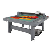
User Manuals: MIMAKI CF2-0912T Flatbed Cutting Plotter
Manuals and User Guides for MIMAKI CF2-0912T Flatbed Cutting Plotter. We have
1
MIMAKI CF2-0912T Flatbed Cutting Plotter manual available for free PDF download: Operation Manual
MIMAKI CF2-0912T Operation Manual (168 pages)
FLAT BED CUTTING PLOTTER
Brand:
MIMAKI
| Category:
Plotter
| Size: 32 MB
Table of Contents
Table of Contents
5
Installation Site
9
Restriction in Use
10
For Safe Operation
11
Precautions in Installation
14
How to Read this Instruction Manual
15
Structure of this Instruction Manual
16
Features of the Device
17
Installation Site
20
Checking the Accessories
22
Effective Cutting Area
23
Configuration and Function
24
Main Unit
24
Head
26
Left-Hand Side Face
27
Operation Panel
28
Connecting the Cables
30
Connecting the Signal Wire Cable for the Blower
30
Connecting the Interface Cable
31
Connecting the Power Cable
31
Turning the Power off
33
Turning the Power on
33
Turning the Power On/Off
33
Emergency Stop
34
How to Reset the Emergency Stop
34
How to Stop the Device in an Emergency
34
LOCAL Mode and the Indication on the LCD
35
Local/Remote Modes
35
REMOTE Mode and the Indications on the LCD
36
Matching the Functions of the Device to the Specifications of the Computer
37
Setting Communication Conditions [INTERFACE]
37
Setting the Commands to be Used [MODE SET] > [COMMAND]
38
Rendering the Set Values on the Personal Computer Effective [MODE SET] > [COMMAND SW]
39
Setting the Response Value with Respect to the Valid Area [MODE SET] > [OH UNIT]
40
Setting the Command Origin [MODE SET] > [ORIGIN]
41
Setting the Resolution (GDP) [MODE SET] > [GDP]
42
Setting for Automatic Head Retract [Auto View]
43
Auto-Off Feature of the Vacuum
45
Auto-Off/Panel-OFF[MODE SET]>[VACUUM]
45
Basic Operation on the Local Menu
48
LOCAL Menu
48
MODE SET Menu
48
Basic Operation on the LOCAL Menu
49
Basic Operation Flow Chart
51
Moving the Head
52
Moving the Head by "VIEW" Function
52
Moving the Head by the Jog Keys
53
Fixing a Work
54
Fixing a Work that Is Comparatively Light in Weight
54
Fixing Heavy-Weight Packing Etc
55
Adjusting the Blade
56
Tangential Cutter
56
Swivel Blade
57
Attaching the Tools
58
Attaching the Pen and the Swivel Blade
59
Attaching the Tangential Cutter
60
Installing the Crease Roller
61
Adjusting the Height of the Head
62
Selecting a Tool [Tool Select]
64
Setting Cutting Conditions [Condition]
65
Setting Items
65
Set Values
67
Setting Cutting Conditions
69
Checking Cutting Conditions [Test Cut]
71
Checking the Status of Tools
75
Setting the Cutting Area [Cut Area]
79
Setting the Origin (Origin for Plotting)
82
Functions that Can be Specified after the Interruption
83
How to Interrupt/Resume the Process
83
Interruption of Processing (Plotting, Cutting or Creasing)
83
Interruption of Processing [DATA CLEAR]
83
Chapter3
85
When Abnormal Conditions Are Encountered
85
If any of the Below-Stated Phenomena Takes Place
86
Cutting Depth Is Insufficient. [CONDITION] > [PRESS CORRECT]
86
[TOOL ADJUST] > [CIRCLE Θ-CORRECT]
86
Corrugated Board Is Cut out at Flutes Though Creasing Is Performed [CONDITION] > [PRESS (Y)]
88
Square Mark Not Detected [TOOL Adjust] > [LIGHT POINTER]
89
Tools Are Not Aligned to each Other [Tool Adjust]
90
Flowchart of Checking and Adjusting Procedures
90
General Explanation of the Adjustment of Tools
91
Adjustment of the Cutter
91
Adjustment of the Offset
94
Adjustment of the Roller
95
How to Adjust the Tools
99
Troubleshooting
101
The Device Not at All Actuates Even When the Power to the Device Is Turned on
101
The Device Fails to Actuate Even When Data Is Transmitted from CAD
101
Error Arises When Transmitting Data
101
The Tool Drags on the Sheet of Paper
101
Dotted Lines or Blurred Lines Are Plotted
102
Troubles for Which Error Messages Are Given on the Lcd
103
Errors that Can be Corrected by Users
103
Errors that Cannot be Corrected by Users
105
Assignment of Pen Numbers [Mode Set] > [Pen Asign]
108
Re-Cut of the same Data [Copy]
110
Setting the Number Cut Function [Mode Set] > [Multi-Pass]
112
Setting the One-Stroke Cutting [Mode Set] > [One Stroke]
114
Setting the Direction of Rotation for the Coordinate Axis [Mode Set] > [Rotate]
115
Setting the Cutter Stroke [Mode Set] > [Z Stroke]
116
Setting the Unit to be Used for Indication [Mode Set] > [Unit]
117
Setting the Dummy Cut Operation of the Swievel Blade [Mode Set] > [Dummy Cut]
118
Alignment of Mechanical Axes to Ruled Lines Printed [Axis Align]
119
Expand the Cutting Area [Expands]
121
Setting of Register Mark Detect
124
How to Display the Register Mark Setting on LCD
124
Precautions in Preparing Data with Register Mark
125
Size of the Square Mark
125
Size of the Register Mark
126
The Area Where Register Marks and Designs Can be Arranged
127
No-Plotting Area Around the Register Marks
128
The Size Of, and the Dhꞏ|Ance Between, Register Marks
131
Color of Register Mark
132
Register Mark Blurred
132
Setting of Register Mark Detect Operation
133
Precautions on Register Mark Detection
133
How to Display the Register Mark Setting on LCD
133
Settings for Detection of Marks
134
Settings for Detect
136
How to Detect Register Mark
137
Continuous Cut with Register Mark
139
Initialize the Register Mark Scale Adjustment [Sc.clr]
140
Chapter6 Self-Test
141
Confirmation of Cutting Quality Only by the Single Unit of the Device [Self Test]
142
Cutting Quality * / Sample * * * / Circle Cutting R
143
Dump Test [Self Test]
145
Executing the Data Dump
145
Execution of the Parameter Dump
147
Replacing the Blade Protrusion
150
Tangential Cutter Blade
150
Swivel Cutter Blade
151
Local Menu Structure
153
T-Head Model
153
TD/TF-Head Model
155
Output Samples
157
Cutting Quality 1
157
Cutting Quality 2
157
ASCII Dump List
157
Sample (Coated)
158
Sample (E Corrugated)
158
Sample (B Corrugated)
159
Circle Cutting R = 3/5/10/20/50/100
159
Parameter Dump List
160
Specifications
161
Basic Specifications
161
Specifications for Interface Specifications
162
Maintenance
163
Cutting Panel Surface
163
Cover
163
Filter Unit
163
Optional Accessories
165
Swivel Cutter Components
165
Tangential Cutter Components
165
Creasing Roller Components
166
Pen Components
166
Optional Products
166
Advertisement
Advertisement
Related Products
MIMAKI CF2-0912
MIMAKI CF2-0912TD
MIMAKI CF2-0912TF
MIMAKI CF2-0912RC
MIMAKI CF2-0912RT
MIMAKI CF22-1225
MIMAKI CF2-1215
MIMAKI CF2-1218
MIMAKI CF2-1218T
MIMAKI CF2-1215TD
MIMAKI Categories
Printer
Plotter
Printer Accessories
Industrial Equipment
Cutter
More MIMAKI Manuals
Login
Sign In
OR
Sign in with Facebook
Sign in with Google
Upload manual
Upload from disk
Upload from URL