
Subscribe to Our Youtube Channel
Related Manuals for MIMAKI CFL-605RT


Summary of Contents for MIMAKI CFL-605RT
- Page 1 You can also download the latest manual from our website. MIMAKI ENGINEERING CO., LTD. URL: http://eng.mimaki.co.jp/ D202786-14 Original instructions...
-
Page 2: Table Of Contents
TABLE OF CONTENTS CAUTION ................vii CAUTION ...............vii FCC Statement (USA) & EN55022 (Europe) ....vii Interference to televisions and radios ......vii Introduction ..............viii On This Operation Manual ..........viii Accessories ..............viii Safety Precautions ............ix Symbols ................ix Warning labels ..............xii Chapter 1 Setup Installation .............. - Page 3 Setting Automatic Head Retraction ...... 1-24 Setting the Vacuum ..........1-25 Enabling / Disabling the Vacuum Automatic OFF Function ..............1-25 Interlock between Remote Key and Vacuum Key .. 1-26 Chpater 2 Basic Operations Basic Operation Workflow ........2-2 Turning the Power ON ........... 2-3 Moving the Head ............
- Page 4 Functions in the Jog Mode ........3-5 Setting the origin ............3-5 Two-point axis alignment ..........3-6 Cutting area ...............3-7 Digitization operation ..........3-8 Assigning Pen Numbers ......... 3-9 Cutting the Same Data Again (Copy) ....3-11 Setting Multi-pass Cutting ........3-12 Setting Multi-pass Cutting ........3-12 Change the cutting (plotting) order .......
- Page 5 Permitted Arrangements of Register Marks and the Design ..............4-3 Prohibited Drawing Areas around Register Marks ... 4-3 Guide to Register Mark Separation and Register Mark Size ................4-5 Register Mark Colors ..........4-6 Bleeding or Smudging of Register Marks ....4-6 Setting Register Mark Detection ......
- Page 6 Drawn lines are broken or smudged .......6-15 No reciprocating movement ........6-15 Problems Causing an Error Display ..... 6-16 Non-fatal Errors ............6-16 Status message ............6-19 Sample Cut ............6-20 Perform SAMPLE CUT to Find out the Cause of Cutting Error............6-21 CFL-605RT Specifications ........6-23...
-
Page 8: Caution
Operation of this equipment in a residential area is likely to cause harmful interference in which case the user will be required to correct the interference at his own expense. In the case where MIMAKI-recommended cable is not used for connection of this device, limits provided by FCC rules can be exceeded. -
Page 9: Introduction
Carefully read this manual and then store it in a place where it can be easily reached. On This Operation Manual • This manual describes the operation and maintenance of the CFL-605RT es Flatbed Cutting Plotter ("the unit"). • Carefully read this manual and then store it in a place where it can be easily reached. -
Page 10: Safety Precautions
Safety Precautions Symbols Symbols are used in this Operation Manual for safe operation and for prevention of damage to the machine. The indicated sign is different depending on the content of caution. Symbols and their meanings are given below. Please follow these instructions as you read this manual. Examples of symbols Meaning Failure to observe the instructions given with this symbol can result in death or serious injuries to... - Page 11 MIMAKI office for maintenance.For some units, capacitors may repair. Never repair your device by yourself take one minute for discharging; therefore, start since it is very dangerous for you to do so.
- Page 12 Safety Precautions For safe operation CAUTION Do not restart the power until 30 seconds after turn off Do not put any matters on the cable • If the device is restarted, do not turn on the • Do not bend the power cable and the power until 30 seconds after turning off.
-
Page 13: Warning Labels
Warning labels Warning labels are stuck on the printer body. Be sure to fully understand the warning given on the labels. If a warning label is illegible due to stains or has come off, purchase a new one from your local distributor or our office. - Page 14 xiii...
- Page 15 Chapter 1 Setup This Section..describes the setup operations required to connect the unit to a PC after unpacking it. Installation ..........1-2 Mounting Tools ........1-11 Names and Functions of Parts ....1-4 Mounting the Pen or Swivel Blade ..1-11 Mounting the Tangential Cutter ....1-14 Main Unit ..........
-
Page 16: Installation
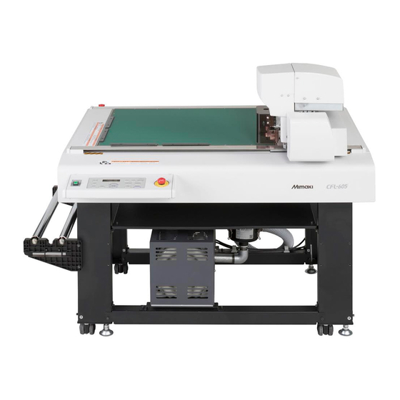
Install the unit in a location where the following installation space is available. • Allow no objects inside the installation space. These may cause you to trip. Model Width Depth Height Total weight CFL-605RT 1,310 mm 1,030 mm 1,100 mm Less than 109 kg 300 mm or more 300 mm... - Page 17 Installation Moving This Machine Move this machine according to the following steps when this machine needs to be moved on the same step- free floor. • When the machine is moved to any place other than on the same step-free floor, contact your distributor or our service office.
-
Page 18: Names And Functions Of Parts
Names and Functions of Parts Main Unit (15) (12) (13) (14) (11) (10) (16) Name Function Y bar Moves the head in the Y direction. Head Holds a variety of tools. The mountable tool depends on the head. Tray Small tools, such as a retractable knife and other cutters, can be placed on. Table Can put temporarily the workpiece and finished product. -
Page 19: Head
Names and Functions of Parts Head Front Name Function Register mark height Used adjust the reading height of mark sensor. ( P.4-11) adjustment lever Register mark height Used adjust the reading height of mark sensor. ? P.4-11) fixing screw Register mark sensor / Sensor to detect register marks. -
Page 20: Operation Panel
Names and Functions of Parts Operation Panel TEST key VACUUM key Turns vacuum adhesion of the workpiece on ( P.2-7). Execute a test cut. VIEW key TOOL key The head is saved to the set location. Change the tool and set the cut conditions. When pressed during jog, can set the axis alignment( P.3-6). -
Page 21: Cable Connections
The unit offers an RS-232C interface and USB interface as standard. Use an RS-232C interface cable recommended by Mimaki or one that suits the PC you are using. Turn off the plotter and PC before connecting the RS-232C interface cable. -
Page 22: Emergency Stop
Emergency Stop The emergency stop is used when an emergency situation arises. EMERGENCY switch is located in two places in the key panel section and rear of the unit respectively. Applying an Emergency Stop Press the EMERGENCY switch. • Operation stops and the unit turns off. Resetting an Emergency Stop Turn the EMERGENCY switch clockwise to unlock it. -
Page 23: Preparing The Cutting Panel
Preparing the Cutting Panel Attach the felt mat If using reciprocating, attach a felt mat or hard mat to match the work to be cut.( P.1-10) • When using the tangential cutter, please use the cutting mat with holes. • When using a reciprocating cutter, please use by placing a felt mat or hard mat on top of the cutting mat. -
Page 24: Blades And Workpieces
Blades and Workpieces The types of workpiece that can be cut and the blade types that can be used differ according to the unit. Workpiece Types that Can be Cut (Guide) Unit Cutt Felt Hard Work Cutter Type Tool Type Mat... -
Page 25: Mounting Tools
Mounting Tools The heads (A, B) that mount tools are shown below. Unit Applicable Tools See page Pen, swivel cutter holder, P.1-11 swivel cutter holder C Grid roller P.1-16 Reciprocating cutter P.1-17 Tangential cutter P.1-17 Mounting the Pen or Swivel Blade •... - Page 26 How to install the cutter holder Rotate the knob to loosen the holder presser. Holder presser Knob Insert the cutter holder into the tool holder. • Push the brim of the cutter holder against the tool holder. • Press the brim of the cutter holder with the l holder presser. Holder presser Brim Attachment of Swivel...
- Page 27 Mounting Tools How to Install a Ballpoint Pen Insert a spring into the pen tip. While pressing the cap onto the spring, attach it on the pen adapter. • Rotate the cap to the direction indicated with an arrow and attach it on the pen adapter.
-
Page 28: Mounting The Tangential Cutter
Mounting the Tangential Cutter Mount the tangential cutter in Unit B. • Do not touch the blade with bare hands. This may cause injury. Mounting the Tangential Cutter Blade Mount the tangential cutter blade in the cutter holder. Use the 2.5 mm hexagonal wrench supplied to loosen the stopper screw. - Page 29 Mounting Tools Replacing the Tangential Cutter "Mounting the Tangential Cutter Blade"Follow steps 1 - 3 to replace the blade. Adjust the amount that the blade protrudes. • For details about the adjustment, see P.2-14. Mounting the Cutter Holder After mounting the cutter, mount the cutter holder into the unit. Loosen the stopper screw.
-
Page 30: Mounting The Grid Roller
Mounting the Grid Roller Mount the grid roller in Unit B. Groove Attach the grid tool to grid holder Grid (1) Remove the set screw of the grid holder holder (2) Plug the grid roller to scribe holder (3) Fixed with set screws Flat part Stopper Grid roller... -
Page 31: Mounting The Reciprocating Cutter
Mounting Tools Mounting the Reciprocating Cutter Attach a reciprocating cutter to B unit. • Do not touch the blade with bare hands. This may cause injury. Mounting the Reciprocating Cutter Blade • A reciprocating cutter holder is required to mount the reciprocating cutter. For Unit B, Model R1 Name: Reciprocating Cutter Holder 07L (SPA-0260) Blade: Carbide 2°x10 (SPB-0086) - Page 32 Mounting Tools Replacing the Reciprocating Cutter Follow steps "Mounting the Reciprocating Cutter Blade" to replace the blade. Mounting the Reciprocating Cutter Holder Press the jog keys in local mode to move the head forward. Turn off the unit power. Loosen the Unit B fixing screw. •...
-
Page 33: Attach The Work Holder
Attach the Work Holder The work holder prevents the work from moving up after it is cut. • The work holder can be used for works of up to 10 mm Work holder thick.The work holder does not support thickness greater than 10 mm. -
Page 34: Local Status / Remote Status
Local Status / Remote Status Press on the operation panel to toggle between the local and remote status. Local Status and Displays The local status permits movement of the heads, setup of the unit functions, and receiving data from the PC. All keys on the operation panel are enabled in local status. - Page 35 Local Status / Remote Status Pen Selected This remote screen appears when HEAD:A, PRS : Cutting pressure < REMOT E > * * * * K B TOOL: Pen is selected for TOOL SELECT in the SPD : Cutting speed A : PEN * * / * * local menu.
-
Page 36: Matching The Pc Specifications
Matching the PC Specifications Setting the Command Origin This setting aligns the unit command origin position with the command origin position in the CAD system used. For more information on the command origin position handled by the CAD system, see the CAD Instruction Manual. -
Page 37: Matching The Plotter Specifications
Matching the Plotter Specifications This unit uses the command MGL-IIC3. Set the CAD command to connect to the unit to MGL-IIC3. • Only the MGL-IIC3 commands are available in MODE SET. This command cannot be changed at the plotter. 1-23... -
Page 38: Setting Automatic Head Retraction
Setting Automatic Head Retraction Sets the time before the head begins to retract to the retraction position when cutting (drawing) of data from the PC is complete. Item Set value No automatic retraction LOW-LEFT Save to the lower left LOW-RIGHT Save to the lower right. -
Page 39: Setting The Vacuum
Setting the Vacuum Sets the vacuum operation when the vacuum is used. Item Set value If automatic head retraction is set to available, the vacuum turns off automatically AUTO OFF after head retraction. Vacuum remains on after head retraction. *1. The vacuum cannot turn off automatically if automatic head retraction is OFF. •... -
Page 40: Interlock Between Remote Key And Vacuum Key
Setting the Vacuum Interlock between Remote Key and Vacuum Key The vacuum key can be turned on/off automatically using the remote key. If a cutting operation is performed without activating the vacuum, the workpiece may float and hinder the cutting operation. - Page 41 Chpater 2 Basic Operations This Section..describes the basic operations, such as mounting tools and workpieces. Basic Operation Workflow ...... 2-2 Adjusting the Swivel Blade .....2-16 Making a Test Cut ........ 2-17 Turning the Power ON......2-3 Checking the Tool Status .......2-18 Moving the Head ........
-
Page 42: Basic Operation Workflow
Basic Operation Workflow This section describes the basic operation workflow. For details, see the reference page shown. Turning the power on See “Turning the power on” (P.2-8) Moving the Head See "Moving the Head"( P.2-4). Fixing the Workpiece See "Fixing the Workpiece"( P.2-6). -
Page 43: Turning The Power On
Turning the Power ON This machine is provided with the following two power switches: Main power switch: Two switches are located on the right side of this machine.Keep this switch ON all the time. Power switch : Normally, use this switch to turn the power ON/OFF. •... -
Page 44: Moving The Head
Moving the Head The head can be moved to a convenient position to mount the workpiece, make a test cut, or mount a tool. Two methods are available to move the head. • Using the head retraction (View) function • Using the jog keys Moving the Head Using the Head Retraction [VIEW] Function The head can be moved at once to the table each corner, or the drawing origin. -
Page 45: Moving The Head Using The Jog Keys
Moving the Head Moving the Head Using the Jog Keys Use this method for mounting tools or making a test cut or sample cut. The following function allows the head to be accurately positioned using the jog keys. The coordinates are displayed with respect to the command origin position. <OR I G I N S E T >... -
Page 46: Fixing The Workpiece
Fixing the Workpiece Two methods are available to fix a workpiece. • Fixing the Workpiece by Vacuum Adhesion • Fixing the Workpiece with Adhesive Tape • The following table shows the acceptable workpiece thicknesses (Maximum value). Workpiece thickness 10 mm •... -
Page 47: Fixing The Workpiece By Vacuum Adhesion
Fixing the Workpiece Fixing the Workpiece by Vacuum Adhesion Relatively thin workpieces, such as thin coated board, corrugated cardboard and sponge, can be fixed by vacuum adhesion. • If all the suction holes are not covered such as the following cases, use some sort of film to cover all the remaining holes. - Page 48 Put the workpiece on the cutting panel. Press...
-
Page 49: Method Of Fixing The Sponge
Fixing the Workpiece Method of fixing the sponge When cut the soft material such as a sponge that can not be adsorbed and fixed, use a adsorption sheet to fix the work in the following ways. Put the workpiece on the cutting panel. Set a roll of adsorption sheet to roll holder Work surface Pull out the adsorption sheet and cover the... -
Page 50: Selecting Tools
Selecting Tools Select the tool condition Before cutting (plotting), select the tool condition depending on the sheet and the tool type to be used. Press the key in LOCAL mode. < TOO L S E L EC T > A : PEN Press key and select Unit. -
Page 51: Set Items
Selecting Tools Set Items The cutting condition set items differ according to the tool. Tool Type Set Item Set value Set value Speed of tool movement in the X or Y direction. CUT SPEED 0.2~30 (cm/s) Changes according to the type of tool and workpiece ○... - Page 52 Tool Type Set Item Set value Set value Centering the original data, drawing two ruled lines W ROLLER OFF, 0.1 ~ 1.0mm ○ offsetting the setting value. OFF, 1~2 (cm/s) Speed for cutting an arc with a radius less than 5 mm. ○...
- Page 53 Selecting Tools The Setting of The W Roller Center the normal ruled line and draw 2 ruled lines to the offset position. • Does not draw the normal ruled line. Offset Offset 0.1~1.0mm 0.1~1.0mm : Normal ruled : Draw 2 ruled lines when W roller is “ON”...
-
Page 54: Adjusting The Blade To Match The Workpiece
Adjusting the Blade to Match the Workpiece This section describes how to adjust a tial cutter blade or swivel blade. • It is not possible to adjust a reciprocating cutter blade. • Handle the blade carefully to avoid injury. For safety, handle the blade with the tweezers supplied. Adjusting the tial Cutter A cutter holder is required to mount the tial cutter. - Page 55 Adjusting the Blade to Match the Workpiece Loosen the dial stopper. • Turn the dial stopper counterclockwise to loosen it. Dial stopper Turn the dial. • Turn in the direction of the arrow. Turning it one revolution extends the blade 1 mm. •...
-
Page 56: Adjusting The Swivel Blade
Adjusting the Blade to Match the Workpiece Adjusting the Swivel Blade After adjusting the blade edge, set the cut condition and perform test cut to check whether cutting is performed well. Adjusting knob Turn the adjusting knob to adjust the protruding amount of the cutter. -
Page 57: Making A Test Cut
Making a Test Cut After changing the cutting conditions or tool, make a test cut to check the items listed below. For details, see "Checking the Tool Status" ( P.2-18). Check Item Check Point cutting (drawing) Work is correcly cut or drawing is not smudged. conditions suitable? Is tool mounted eccentrically? An eccentric tool can cause displacement in the cutting or drawing. -
Page 58: Checking The Tool Status
Checking the Tool Status Make a test cut using the tool selected by the Tool Select function. This section describes the check items for each tool. Point A Point B Point C Point D Point D' Check Point Cause Remedy See page Point A contact points do Pen incorrectly mounted. -
Page 59: Crease Roller
Making a Test Cut Crease Roller Check Point Cause Remedy See page Point A contact points do Conduct Adjust Eccentricity in tool Blade is mounted eccentrically P.6-4 not match adjustments. Abnormal angle of crease Conduct Adjust tool Lines displaced at Point A P.6-9 roller adjustments. -
Page 60: Checking The Status Between Tools
Checking the Status Between Tools Make a test cut to check the status between the tools (pen and tial cutter or pen and crease roller). Check Method Draw the pattern with the pen. Then make a test cut at the same position using the tial cutter or crease roller to check the status between tools. - Page 61 Making a Test Cut Overview Sample D Cutting end point is too long or too short. Remedy1 Adjust the END CORR. value in the cutting conditions. ( P.2- Remedy2 Adjust Pattern A for Adjust Eccentricity in Adjust Cutter in tool adjustments.
- Page 62 Making a Test Cut Overview Sample H The cutting start point is too far forward or backward, and the tial cutter is displaced to the right or left. Remedy See the remedies described for Sample C and Sample E. Overview Sample I The cutting end point is too long or too short, and the tial cutter is displaced to the right or left.
-
Page 63: Setting The Drawing Origin
Setting the Drawing Origin The origin is the reference point for drawing, cutting, and grid Data cutting. (It is normally set at the lower-left corner of the maximum effective cutting area.) The drawing position moves as the origin is moved. Max. -
Page 64: Cutting (Drawing)
Cutting (Drawing) Effective Cutting Area The table below shows the maximum effective cutting area. Model Name X-axis (mm) Y-axis (mm) CFL-605RT Maximum effective cutting area Y-axis Cutting (Drawing) Set the origin and press • The remote mode is selected. •... -
Page 65: Interrupting Processing
Cutting (Drawing) Interrupting Processing Follow the procedure below to interrupt data processing during drawing, cutting, or grid cutting in remote status for any reason. Press during unit operation. Restarting Processing Press • The unit enters remote status and processing restarts. Functions that Can Be Set After Interrupting Processing ... -
Page 66: Interrupting Processing (Data Clear)
Cutting (Drawing) Interrupting Processing (Data Clear) In the following cases, clear the received data from the receive buffer. (1) To clear an interrupted cutting (drawing) file from the receive buffer, without restarting processing. (2) To clear received but unprocessed data from the receive buffer. (3) To clear data remaining in the receive buffer before receiving data from running the SINGLE COPY function. -
Page 67: Turning The Power Off
Turning the Power OFF Before turning OFF the power, confirm that no data is being received and no un-output data remains. Turn off the connected PC. Press the power switch to turn the power OFF. • Push the power switch located on the operation panel. •... - Page 68 2-28...
- Page 69 Chapter 3 Useful Function This Section..describes the basic operations, such as mounting tools and workpieces. List of SET UP Functions ....... 3-2 Other Useful Functions......3-21 Functions in the Jog Mode ..... 3-5 Setting a Cut Quality .......3-21 Setting speed of carriage movement ..3-22 Setting the origin ........
-
Page 70: List Of Set Up Functions
List of SET UP Functions This section describes the overview of each function to be set and set values that can be registered in user types. Function name Set value Default Outline PEN, No.1 Unit: A SWIVEL B:REC.CUTTER1 No.2 B:ROLLOR1 This section describes how to assign REC.CUTT PEN ASSIGN... - Page 71 List of SET UP Functions Function name Set value Default Outline START MODE( P.3-27) LOCAL, REMOTE LOCAL Set the mode after the power is turned on. This is to select the unit with which you MM/INCH( P.3-17) mm, inch want to display the length. 0.1mm, 1.0mm 0.1mm This is to set the moving amount of...
- Page 72 List of SET UP Functions Function name Set value Default Outline SMTP Addr. Set the SMTP server. SMTP Port Set the SMTP port number. Set the e-mail address to be used as SENDER Addr. the sender mail address. POP before SMTP before Set the SMTP server authentication...
-
Page 73: Functions In The Jog Mode
Functions in the Jog Mode Press the jog key in the local mode, and then you can enter the jog mode, where you can perform the following settings. Reference Function names Contents page Setting the origin Set the point from which the plotter will start cutting (plotting). P.3-5 If a ruled sheet is set, align the horizontal and vertical axes with the Two-point axis alignment... -
Page 74: Two-Point Axis Alignment
Two-point axis alignment If a ruled sheet is set, align the horizontal and vertical axes Compensation point with the appropriate lines on the sheet. Correct the axial inclination (θ) by setting a compensation point in combination with the origin. Origin Press the key to set to the local mode. -
Page 75: Cutting Area
Functions in the Jog Mode Cutting area Set the area in which the plotter performs cutting (plotting). The area that has a diagonal line extending from the origin to a given UR (upper right) point is the available cutting area. The cutting area setting will be cleared by turning the Upper-right power off. -
Page 76: Digitization Operation
Functions in the Jog Mode Digitization operation The coordinates of the plotted figure relative to the origin are displayed on the host computer. Upon receiving the digitization command (DP;) from the host computer, the plotter is ready for digitization operation. To conduct digitization, install a sheet with patterns to select points on it. -
Page 77: Assigning Pen Numbers
Assigning Pen Numbers This section describes how to assign pen numbers in the data to tools on the unit. For this unit, up to six pens can be assigned to each tool. This example describes how to make the following settings. Pen 1 (pen number in drawing data) : Set to PEN. - Page 78 Assigning Pen Numbers Press the key. < P EN N o . S E L EC T > N o . 1 A : P EN Press the jog key and select the pen < P EN N o . S E L EC T >...
-
Page 79: Cutting The Same Data Again (Copy)
Cutting the Same Data Again (Copy) Previously cut data can be cut again in offline status. This eliminates the need to send the same data many times from the PC. • Use DATA CLEAR to clear ( P.2-26) the receive buffer before receiving the data to be copied. If the data is not cleared, the other data in the receive buffer will be copied. -
Page 80: Setting Multi-Pass Cutting
Setting Multi-pass Cutting Setting Multi-pass Cutting While changing the press value, can cut the same data up to 9 times for each tool. This is an effective means of cutting a workpiece that cannot be cut in one pass. • Set the cut start time (Close time P.3-20) that sets the delimiter between data. - Page 81 Setting Multi-pass Cutting Press , select the number of times to set <MU L T I P AS S > 2 n d PRE S S : 1 0 0 0 g the cut press value and press Set the cut press value by pressing the jog key <MU L T I P AS S >...
-
Page 82: Change The Cutting (Plotting) Order
Change the cutting (plotting) order You can reorder or sort the cut data that has been sent from the host computer to change the order for cutting (SORTING function). Suppose that there is data that you want to cut just like drawing a picture with a single stroke, according the order in which data is sent from application software. -
Page 83: Rotating Coordinate Axes (Rotate)
Rotating Coordinate Axes (ROTATE) This function sets the location of origin and direction of the axes of coordinates according to the application software to be used. (ROTATION function) Rotating function : OFF Rotating function : ON Origin Origin • Confirm that any data to be cut is not saved in the receiving buffer. If you change the set values, the contents of the receiving buffer are cleared completely. -
Page 84: Setting The Cutter Stroke
Setting the Cutter Stroke This setting shortens the distance that the tool rises when cutting (or drawing) data with frequent up/down movements of the tial cutter or grid roller. It thereby reduces the total cutting time. Select [PLOT SETTING] of the set up menu. (1) Press the key in LOCAL. -
Page 85: Setting The Displayed Units
Setting the Displayed Units Sets the units for the values displayed on the screen. Set value Description Displays millimeters. Displays inches. inch Press the key in the local mode. < F UNC T I ON > FUNCTION S E T UP [ EN T ] Press the jog key to select [SET UP],... -
Page 86: Swivel Blade Dummy Cut
Swivel Blade Dummy Cut When turn on the power in the state that set the swivel cutter in the tool set, or when select the swivel cutter after the power is turned on, dummy cut is made outside the effective cutting area in order to direct the cutting edge of the swivel cutter in the traveling direction. -
Page 87: Setting The Displayed Language (Display)
Setting the Displayed Language (DISPLAY) Select English or Japanese as the displayed language. Press the key in LOCAL < F UNC T I ON > FUNCTION S E T UP < EN T > Press and select [DISPLAY]. ... -
Page 88: Setting The Close Time
Setting the Close Time After cutting (plotting) the data that was sent from PC, following operation starts automatically at the time that had been set in advance. • Data clear ( P.2-26) • Automatic Head Retraction ( P.1-24) • Vacuum Automatic OFF ( P.1-25) •... -
Page 89: Other Useful Functions
Other Useful Functions Setting a Cut Quality This is to set the cutting quality. Select [PLOT SETTING] of the set up menu. (1) Press the key in LOCAL. FUNCTION (2) Press to select [SET UP] and press the key. (3) Press to select [PLOT SETTING]. -
Page 90: Setting Speed Of Carriage Movement
Setting speed of carriage movement This is to set the speed of carriage movement when the tool is up. Select [PLOT SETTING] of the set up menu. (1) Press the key in LOCAL. FUNCTION (2) Press to select [SET UP] and press the key. -
Page 91: Height Setting At The Pen Tool Lifted
Other Useful Functions Height setting at the pen tool lifted Set the height when lifting the tool. Select [PLOT SETTING] of the set up menu. (1) Press the key in LOCAL. FUNCTION (2) Press to select [SET UP] and press the key. -
Page 92: Setting Of The Offset Value Of The Cutting Edge Correction Pressure
Setting of the offset value of the cutting edge correction pressure Set when there is an uncut at the start point and end point of the cut. Select [PLOT SETTING] of the set up menu. (1) Press the key in LOCAL. FUNCTION (2) Press to select [SET UP] and press the... -
Page 93: Make The Media Without Uncut Area
Other Useful Functions Make the media without uncut area By over lapping the start point and the end point arbitrarily, you can make the media without uncut area. Specify the over cut function (valid/invalid) and the length of the over cut. -
Page 94: Setting A Key Buzzer
Setting a KEY BUZZER You can turn off the buzzer sound when pressing the key. Press the key in LOCAL. < F UNC T I ON > FUNCTION S E T UP [ EN T ] Press to select [SET UP]. ... -
Page 95: Setting A Start Mode
Other Useful Functions Setting a START MODE Set the mode after power ON. Press the key in LOCAL. < F UNC T I ON > FUNCTION S E T UP [ EN T ] Press to select [SET UP]. ... -
Page 96: Setting A Jog Setting
Setting a JOG SETTING This is to set the moving amount of carriage via the jog key. Press the key in LOCAL. < F UNC T I ON > FUNCTION S E T UP [ EN T ] Press to select [SET UP]. -
Page 97: Setting A Command
Other Useful Functions Setting a COMMAND Setting a PRIORITY When this plotter and the host computer make different settings on a same item, this function is used to set about which of the two must be given priority to Select [COMMAND SETTING] of the set up menu. (1) Press the key in LOCAL. - Page 98 Setting the Effective Area Return Values (OH UNIT) Sets which value to return to the CAD system when the unit receives the effective area coordinate output command from the CAD system. INITIAL: Return the maximum value of the effective cutting area of the machine. SET VAL: Returns the value that was set in the configuration of the cut area.
- Page 99 Other Useful Functions Resolution (GDP ) Setting This setting aligns the resolution of the unit with the resolution of the CAD system used. For more information on the resolution of the CAD system, see the CAD Instruction Manual. Select [COMMAND SETTING] of the set up menu. (1) Press the key in LOCAL.
-
Page 100: Set The Configurations With A Computer
Set the configurations with a computer Set the configurations with a computer Set the communication condition with the RS-232C interface. Select [INTERFACE] of the set up menu. (1) Press the key in LOCAL. FUNCTION (2) Press to select [SET UP] and press the key. - Page 101 Other Useful Functions Press the key to confirm the value. When you want to terminate this procedure, press the key twice. Setting Items Boud rate 1200, 2400, 4800, 9600, 19200, 38400(bps) Data bits 7, 8(bit) Parity NON, EVEN, ODD Stop bits 1, 2(bit) Handshake HARD, ENQACK, X-PRM, SOFT...
-
Page 102: Set The Network
Set the network You can also perform network setting with “Network Configurator”, the tool to perform network setting of Mimaki’s product. To download the Network Configurator, check " Driver / Utility" on the download page at Mimaki Engineering (http://eng.mimaki.co.jp/download/). Select [INTERFACE] of the set up menu. - Page 103 Other Useful Functions Press the jog key to select [DHCP] . < NE TWORK > DHCP : ON Press the key. < NE TWORK > DHCP : ON • Press to set ON/ OFF. • When it is ON, the IP address given by the DHCP server is used. Press the key.
-
Page 104: Setting Event Mail Function
You can also perform network setting with “Network Configurator”, the tool to perform network setting of Mimaki’s product. To download the Network Configurator, check " Driver / Utility" on the download page at Mimaki Engineering (http://eng.mimaki.co.jp/download/). Disclaimer •... - Page 105 Other Useful Functions Set the event to send an event mail Select [INTERFACE] of the set up menu. (1) Press the key in LOCAL. FUNCTION (2) Press to select [SET UP] and press the key. (3) Press to select [INTERFACE]. (4) Press the key.
- Page 106 Set the e-mail address Select [INTERFACE] of the set up menu. (1) Press the key in LOCAL. FUNCTION (2) Press to select [SET UP] and press the key. (3) Press to select [INTERFACE]. (4) Press the key. Press the jog key to select [EVENT ...
- Page 107 Other Useful Functions Set the subject Select [INTERFACE] of the set up menu. (1) Press the key in LOCAL. FUNCTION (2) Press to select [SET UP] and press the key. (3) Press to select [INTERFACE]. (4) Press the key. Press the jog key to select [EVENT ...
- Page 108 Set the server Select [INTERFACE] of the set up menu. (1) Press the key in LOCAL. FUNCTION (2) Press to select [SET UP] and press the key. (3) Press to select [INTERFACE]. (4) Press the key. Press the jog key to select [EVENT ...
- Page 109 Other Useful Functions Press the jog key to select [Sender S ERV ER S E T UP Adr]. S ENDER A s s r . [ EN T ] Press the key. S e n d e r Ma i l A d d r e s s .
- Page 110 Press the key. P a s s Wo r d * * * * * * * * * * * * * * * • Press to set the password to use for the authentication. • Set it with alphanumeric characters and symbols within 15 characters. •...
- Page 111 Other Useful Functions Send a test e-mail Select [INTERFACE] of the set up menu. (1) Press the key in LOCAL. FUNCTION (2) Press to select [SET UP] and press the key. (3) Press to select [INTERFACE]. (4) Press the key. Press the jog key to select [EVENT ...
- Page 112 • The sent result of the test e-mail is the result of e-mail sending process performed by this machine to the e-mail server. It does not indicate that the e-mail was received at the address. • If the spam e-mail filter etc. has been set in the terminal in which e-mails are received, even if “Sending has been completed”...
-
Page 113: Copy The Set Value From The Other User Setting
Other Useful Functions Copy the set value from the other user setting Press the key in the local mode. < F UNC T I ON > FUNCTION S E T UP [ EN T ] Press the jog key to select [SET UP] . -
Page 114: Reset The Setting Values To The Initial State
Other Useful Functions Reset the setting values to the initial state. Press the key in the local mode. < F UNC T I ON > FUNCTION S E T UP [ EN T ] Press the jog key to select [SET UP] . -
Page 115: Switch The User
Switch the User You can save the setting value (cutting condition and main body setting) by five users from the User 1 to 4, Temp. user. By changing the user number depending on the user, you can change the environment without resetting these parameters. - Page 116 Confirming Machine Information The information of this machine can be confirmed. The following items can be confirmed as machine information. Item Description MODEL This displays the model name of the machine. SERIAL No. This displays the serial number of the machine. IP Address This displays the IP address of the machine.
- Page 117 Chapter 4 Register Mark Reading Functions This Section..describes the basic operations, such as mounting tools and workpieces. Precautions when Creating Data with Detecting Register Marks ..... 4-10 Register Marks ........4-2 Using the Light Pointer to Check the Workpiece Tilt .........4-10 Size of Register Marks ......
-
Page 118: Precautions When Creating Data With Register Arks
Precautions when Creating Data with Register Marks Several restrictions apply when creating data with register marks. To get the best out of the register mark functions, carefully read the precautions below to gain the knowledge required when creating register marks. •... -
Page 119: Permitted Arrangements Of Register Marks And The Design
Precautions when Creating Data with Register Marks Permitted Arrangements of Register Marks and the Design Starting position of TP1 should be more than 10mm away from the end of workpiece and place within 10mm from maximum cutting area. The possible range of design placement is 610x510mm at maximum. •... - Page 120 False Detection of Register Marks - Example 1 Plate displacement during offset printing • Color printing by offset printing requires the output of CMYK plates. A slight displacement between these plates also causes a displacement of the printed register marks. •...
-
Page 121: Guide To Register Mark Separation And Register Mark Size
Precautions when Creating Data with Register Marks False Detection of Register Marks - Example 3 Register mark separation (TP2 to TP1; TP4 to TP2) does not exceed the register mark length. For sType1 register marks Prohibited drawing area Separate by at least the register mark length Prohibited drawing area Separate by at least the... -
Page 122: Register Mark Colors
Precautions when Creating Data with Register Marks Register Mark Colors The mark must be printed in black against the white background. The registration mark will not be detected correctly if the background is not white or the mark is not black. Good No Good Bleeding or Smudging of Register Marks... -
Page 123: Setting Register Mark Detection
Setting Register Mark Detection Precautions Related to Register Mark Detection • To set the distance between the printed register marks the same as the cut distance, enter the distance between the printed register marks used for register mark detection. ( P.4-12) •... - Page 124 Set Item Set value Description Select from three register mark styles: TYPE1 TYPE2 TYPE1 FORM TYPE2 Panel Panel Effective when the same pattern is multi-printed at regular intervals. Cuts automatically the preset number of sheets while detecting registration marks consecutively based on the first data. When the number of copies can be set on the application software, like on the supplied COPIES X (->)
-
Page 125: Setting Register Mark Detection
Setting Register Mark Detection Setting Register Mark Detection Press the key in the local mode. FUNCTION < F UNC T I ON > S E T UP [ EN T ] Press the jog key to select [SET UP] . ... -
Page 126: Detecting Register Marks
Detecting Register Marks The unit can automatically detect register marks printed on the workpiece to cut round outlines of designs printed on the workpiece. • If the workpiece has curled, flatten it out. • If using cutting software that does not offer register mark functions, ensure that the areas between TP1 and TP3 and between TP1 and TP2 are free of images and dirt. -
Page 127: Setting Height Of Register Mark
Detecting Register Marks Setting height of register mark Reading the register mark and set the height of the sensor. • After cutting the data with mark sensor, lift up the mark sensor. When set a felt mat while lowering the mark sensor, the set guide plate may be hit by the head and may cause the head damage. -
Page 128: Register Mark Detection Procedure
Detecting Register Marks Register Mark Detection Procedure Mount the workpiece. Press in local mode. <MARK DE T EC T > X : + 0 0 0 0 . 0 Y : + 0 0 0 0 . 0 • The mark search mode is selected. Press the jog keys to accurately align the light pointer to the positions shown below. -
Page 129: Continuous Cutting Of Register Marks
Continuous Cutting of Register Marks The FineCut cutting software permits continuous cutting of workpieces with only one set of register mark data printed. • Select “multi mode” when cutting plural images printed on one media. • When data remains in the receive buffer, the remaining data will also be cut. Be sure to carry out the Data Clear operation before performing continuous cutting. -
Page 130: Confirm The Following When Failed In Cutting Correctly
Confirm the following when failed in cutting correctly Alignment of MARK SENSOR The offset value of the cutter and the mark sensor can be adjusted. Set the sheet on which the register mark is printed. Install a cutter in the tool holder. Confirm that the plotter is in the local mode. - Page 131 Confirm the following when failed in cutting correctly Enter the corrected value (mm) by pressing the < S E N S O R O F F S E T > X = - 0 . 2 mm Y = - 0 . 2 mm for the X direction, or the the Y direction.
-
Page 132: Check The Sensor For The Registration Mark Detection
Check the sensor for the registration mark detection Prepare the sheet on which the registration mark is printed. • If you move the head and sheet manually, you cannot perform the right response check. Be sure to perform it via the following operations. For conditions of already printed registration mark, refer to “Precautions when Creating Data •... - Page 133 Confirm the following when failed in cutting correctly Select [SENSOR CHECK] by pressing the jog key < MA R K S E N S O R > S E N S O R C H K [ E N T ] Press the key.
- Page 134 Detect operation Scan in the Y direction (plus direction) to detect the line. • The buzzer sounds when the line is detected. If the line is not detected, the buzzer does not sound. Scan in the Y direction (minus direction) to detect the line.
-
Page 135: Correct The Light Pointer Position
Confirm the following when failed in cutting correctly Correct the light pointer position If the plotter fails to recognize any registration mark properly, the possible cause is an error in the positional relationship between the MARK sensor and the light pointer. In this case, adjust the position of the light pointer. -
Page 136: Setting Of The Back Side Cut Offset
Setting of the back side cut offset When cut the surface with the back side cut, set the Registration offset value of the outer frame of the register mark. mark Outer frame Offset Install a penin the tool holder. Copy paper Set the copy paper. - Page 137 Confirm the following when failed in cutting correctly Measure the distance from the set guide plate to Pattern the pattern Set guide plate Press the jog key to select A or B. < B ACK S I DECU T OF S > ...
- Page 138 4-22...
- Page 139 Chapter 5 Daily Maintenance This Section..describes how to maintain the unit and how to replace the head with an optional head. Daily Maintenance ..............5-2 Cutting Panel Surface ..............5-2 Covers ..................5-2 Care of the cutter blade ..............5-2 Unit B ..................5-3 Cleaning the Vacuum Filter ............5-4 Cleaning the Register Mark Sensor ..........5-5 Supplied items ...............
-
Page 140: Cutting Panel Surface
Daily Maintenance Periodic cleaning is recommended to ensure continuous satisfactory use of the unit. • Do not use an abrasive cleaner or thinners. These could deform the covers or cutting panel. Cutting Panel Surface Clean the air holes with a fine needle if they become blocked. The blocking foreign matter will be discharged from the vacuum outlet. -
Page 141: Unit B
Daily Maintenance Unit B The reciprocating shaft may cease moving if lubrication is inadequate. Before the work of the day, apply the grease to vibration axis. • This work is done in the state of power supply OFF. • Keep the tool removed. Shaft •... -
Page 142: Cleaning The Vacuum Filter
Cleaning the Vacuum Filter The workpiece adhesion force will decrease if the filter becomes blocked in the vacuum. Clean the filter periodically (about once a month). • When clean the filter, please wear gloves. Handling the filter with bare hands may cause injury. Remove the lid. -
Page 143: Cleaning The Register Mark Sensor
Daily Maintenance Cleaning the Register Mark Sensor Wipe dust generated during cutting off the register mark sensor with a clean, dry waste. In addition, when Y bar rail is dirty, noise occurs. After wiping off the dust with a dry lint-free cloth, take the attached grease to lint-free cloth and apply to the rail. Register mark sensor 軸... -
Page 144: Supplied Items
Supplied items Purchase them in a distributor in your district or our office. Supplied items Supply items Part Name Part No. Remarks High-speed steel blade 30° SPB-0043 Accessories tial cutter Carbide blade 30° SPB-0045 Reciprocating cutter Reciprocating cutter 2° x10 SPB-0086 SPB-0075 Carbide blade 7x15... - Page 145 Troubleshooting........6-14 Perform SAMPLE CUT to Find out the Cause Unit does not operate when the power is of Cutting Error........6-21 CFL-605RT Specifications....6-23 turned ON ..........6-14 Unit does not operate after the CAD data is sent ............6-14 An error occurs when the data is sent ..
-
Page 146: Now What Do I Do
Now What Do I Do? Problem Solution Inadequate cutting The workpiece can be reliably cut by increasing the • When the cutter descends, cutting is incomplete, pressure when the cutter descends. although the blade protrudes by more than the • Set or increase the pressure offset value that is added workpiece thickness. -
Page 147: Adjusting The Tools
Adjusting the Tools Tool adjustment is required if the start and end points do not match when cutting (drawing) with the unit. Tool adjustment is possible only when using Model R1 or Model TF2. The following four tool adjustments are available: (1) Cutter adjustment .... - Page 148 Adjusting Eccentricity Adjust the eccentricity by checking the test pattern drawn by the cutter or roller. • First, mount a pen in Unit A. Test pattern drawn by the cutter Test pattern drawn by the roller Normal patternA Normal patternB Normal patternA Normal patternB 20mm...
- Page 149 Adjusting the Tools Press key. < T ES T P A T T ERN > DRAW: [ EN T ] POS : [ J OG ] Press the jog keys to move the head to the drawing position. Press to start drawing the test pattern. Press key to return to the selection of the ...
- Page 150 Adjusting the Eccentricity The eccentricity can be adjusted on the screen below. Adjusting Pattern B Adjusting Pattern A Adjustment to check whether the tool is tilted. Aligns the center of the cutter (roller) with the center of Press to adjust. (0.05 mm pitch) the holder.
- Page 151 Adjusting the Tools Adjusting the Offsets Conduct positioning to correct for displacements by comparing Normal test pattern a test pattern drawn by the pen with a test pattern drawn by the cutter or roller. • First, mount a pen in Unit A. 30mm Press the key in the local mode.
- Page 152 Press the jog key to select X or Y. <OF F S E T AD J US T > OF F S E T Y : 0 . 0 0 mm Press the key. Press to adjust. <OF F S E T AD J US T > OF F S E T Y : 1 .
- Page 153 Adjusting the Tools Adjusting the Angle Adjust the angle of rotation by comparing a test pattern drawn Normal 30 (200)mm test pattern by the pen with a test pattern drawn by the cutter or roller. • Values in parentheses ( ) in the diagram show the sizes of Roller.
- Page 154 Press key to return to the selection of the < AD J US T > < CEN T ER AD J US T > : CEN T ER A : 0 . 0 0 º 1 . 0 0 mm adjustment value.
-
Page 155: Circle Correction
Adjusting the Tools Circle Correction Conduct the operations below to correct for displacements if the start and end points do not match when cutting (drawing) a circle. Setting Arc Correction Before setting circle correction, set arc correction to Enable. Press the key in the local mode. - Page 156 Circle Correction The unit can conduct correction for five circles of different radius. Circle type for correction Set values Radius (R) ≤ 5 mm - 20° ~ + 20° 5 mm < Radius (R) ≤ 10mm - 20° ~ + 20° 10 mm <...
- Page 157 Adjusting the Tools Press key. < T ES T P A T T ERN > DRAW: [ EN T ] POS : [ J OG ] Press the jog keys to move the head to the drawing position. Press to start drawing the test pattern. Press key to return to the selection of the <...
-
Page 158: Troubleshooting
Troubleshooting Make some final checks if you think that the unit has broken down. Contact your Mimaki representative if the problem cannot be solved by the remedy described. Unit does not operate when the power is turned ON Is the power connected properly ? Correctly connect the power cable. -
Page 159: Tool Lifts Up The Paper
P.2-6) Turn off the power and move Unit A vertically. Is pen up / down operation defective? Contact your Mimaki representative if Unit A does not move up and down normally. Change the Z stroke value. Isn't Z stroke too small? P.3-16) -
Page 160: Problems Causing An Error Display
Remedy Trouble has occurred in the control ERROR C02 RAM. MAIN RAM Contact your dealer or a sales office of MIMAKI. Trouble has occurred in the system ERROR C04 EEPROM ROM. Code other than command data has Check the command setting on the... - Page 161 Confirm the status and the settings described above. still registration mark detected, contact your distributor or a sales office of MIMAKI. The origin point was detected Arrange registration marks ERROR C37 MARK ORG outside the cutting area. inside the sheet.
- Page 162 An excessive load was applied to ERROR 462 appears, contact your distributor or MOTOR motor. a sales office of MIMAKI. An overcurrent error in the motor in ERROR 464 CURRENT motor. An excessive load was applied to...
-
Page 163: Status Message
Problems Causing an Error Display Status message The messages given below appear in the remote mode. They do not indicate errors but require an appropriate action. Message Cause Remedy The cutting data exceeds the effective Either increase the size of the cut area or ** OFFSCALE ** cutting area. -
Page 164: Sample Cut
Sample Cut IIn case that normal data cutting cannot be performed etc., perform cutting with the sample stored in this plotter to find out the cause of cutting error. • If there is data that has not been cut in the receive buffer, an error is displayed and can not cut the sample. -
Page 165: Perform Sample Cut To Find Out The Cause Of Cutting Error
Sample Cut Perform SAMPLE CUT to Find out the Cause of Cutting Error. The pen number must assigned before conducting PATTERN CUT or SAMPLE CUT. ( P.3-9) Set the following values as the initial values. Pen No. Model R1 Head Tool Reciprocating cutter 1 (Set a vibration to other than OFF) Head... - Page 166 Sample Cut Result of SAMPLE CUT Sample data can be cut successfully, but other data cannot. The host computer is faulty. Sample data as well as other data cannot be successfully cut either.(When leaving the start/end lines without cutting off) Increase the set value of [ADJ-PRS OFS] ( to raise the pressure for pressing the cutter blade down.
-
Page 167: Cfl-605Rt Specifications
CFL-605RT Specifications Type CFL-605RT SPECIFICATIONS X axis 610 mm Effective plotting width Y axis 510 mm X axis 660 mm Maximum set work size Y axis 555 mm Driving method X, Y, Z, θ axis: ,DC servo motor XY: 423mm / sec (45º direction) - Page 168 6-24...
- Page 169 D202786-14-30062016...
- Page 170 © MIMAKI ENGINEERING CO., LTD.2016 FW : 1.5...
Need help?
Do you have a question about the CFL-605RT and is the answer not in the manual?
Questions and answers