
Related Manuals for GEA Futuro


Summary of Contents for GEA Futuro
- Page 1 Futuro Underground Manure Pumps Instruction Manual / Installation Instructions (Original instructions) 2007-9015-001 03-2014 engineering for a better world GEA Farm Technologies...
-
Page 2: Table Of Contents
..............Connecting the Futuro to the hydraulic power unit . - Page 3 Operation ..............Special personnel qualification required for operation .
-
Page 4: Preface
Preface Information on the instructions Preface Information on the instructions The manufacturer reserves the right to make changes due to technical developments in the data and images given in this manual. Reproductions, translations and copies of any kind, even of extracts, require written authorization from the manufacturer. - Page 5 Preface Information on the instructions Pictograms used This pictogram indicates information that will help towards better understanding of a procedure or operation. This pictogram indicates a special tool required for installation. This pictogram refers to another document or another section of this manual.
-
Page 6: Manufacturer Address
Preface Customer services Manufacturer address GEA Farm Technologies Canada Inc. / Division GEA Houle 4591 boul. St-Joseph Drummondville, Qc, J2A 0C6 +1 819 477 - 7444 +1 819 477 - 5565 geahoule@gea.com www.gea-farmtechnologies.com Customer services authorized Technical Dealer If necessary, please contact your nearest authorized technical dealer. -
Page 7: Declaration Of Conformity
The undersigned is acting by virtue of power of attorney from the management of: GEA Farm Technologies Canada Inc. / Division GEA Houle, 4591 boul. St-Joseph, Drummondville, Qc, J2A 0C6 This declaration certifies compliance with the guidelines indicated, but does not establish any guarantee in the sense of paragraphs 443, 444 of the BGB. -
Page 8: Gea Houle Inc. - General Equipment Warranty
1.5.1 Limited warranty GEA Houle Inc. (hereinafter referred to as ”the Company”) warrants to the original buyer and end user (hereinafter referred to as the ”Purchaser”) that the parts of all equipment sold under the Company trademark are free from defects in material or workmanship for a period of twelve (12) months from the date of delivery of the equipment to the Purchaser. - Page 9 Preface GEA Houle Inc. - General Equipment Warranty 1.5.3 Extent of limited warranty This limited warranty DOES NOT cover: ● Defects caused by negligence of the Purchaser in the maintenance of the equipment, improper use resulting from failure to adhere strictly to the...
- Page 10 Preface GEA Houle Inc. - General Equipment Warranty 1.5.4 Warranty limitations and exclusion NO WARRANTY, ORAL OR WRITTEN, EXPRESS OR IMPLIED, OTHER THAN THE ABOVE WARRANTY IS PROVIDED IN RESPECT OF THE EQUIPMENT SOLD. Some states (or jurisdictions) do not allow the exclusion of implied warranties so it is possible that this limitation may not apply.
-
Page 11: Specific Limited Warranty For Steel Evacuation Line
This specific limited warranty extends to the Purchaser of all evacuation line equipment (the ”Evacuation Line”) sold by the Company in connection with any Magnum or Futuro underground manure pumps. All conditions stated in this specific limited warranty are in addition to the General Equipment Warranty that applies to all equipment sold by the Company (see Section 1.5 above). -
Page 12: Safety
Safety Owner's obligation of care Safety Owner's obligation of care The product has been designed and constructed while taking account of a potential risk analysis and after careful selection of the harmonized standards and other technical specifications to be complied with. It therefore guarantees a maximum level of safety. - Page 13 Safety Owner's obligation of care ● The equipment have been installed in an environment free of explosive gases. ● Enough light is provided in each operation and maintenance area to light up equipment, controls and safety stickers. To ensure adequate visibility of safety stickers applied on the equipment, lights must provide 200 lux minimum at these areas.
-
Page 14: Explanation Of The Safety Symbols Used
Safety Explanation of the safety symbols used Explanation of the safety symbols used Safety symbols draw attention to the importance of the adjacent text. The design of the warnings is based on ISO 3864-2 and ANSI535.6. Safety symbols and signaling word Danger! The indication ”Danger”... -
Page 15: Basic Safety Instructions
Safety Basic safety instructions Basic safety instructions Safety procedures in confined spaces Danger! Manure produces toxic gases that may cause death in a second. When agitated, the manure produces heavy toxic gases such as hydrogen sulfide (H S), carbon dioxide (CO ), methane (CH ) and ammonia ). - Page 16 Safety Basic safety instructions ● All electrical work must be carried out by an electrician. ● Follow the maintenance and safety instructions on the labels affixed to the equipment. ● Keep hands, feet and clothing away from all moving parts. ●...
-
Page 17: Personnel Qualification
Safety Personnel qualification Personnel qualification All personnel who perform work on or with the product must carefully read and understand the instructions and act in accordance with them! ● The operator may only carry out work on the equipment if trained, instructed and authorized to do so by the owner. -
Page 18: Protective Devices
Safety Protective devices Protective devices ● Safety guard Hydraulic power unit chain joint safety guard (part no. 2007-1402-710) ● Safety symbols, warnings, warning signs and labels Danger! - Toxic gases (American model) Manure produces toxic gases that can cause loss of consciousness, asphyxia or death in a few seconds. - Page 19 Safety Protective devices Read the instruction manual for safety information. (European model) (part no. 2099-4725-470) Read the operator's manual for safety information before service and maintenance. (European model) (part no. 2099-4725-130) Always make sure that the top of the piston is covered with at least 2”...
-
Page 20: Description
Correct use also includes reading the instructions and following the inspection and maintenance instructions. ● Original GEA Houle parts and accessories are specially designed for GEA Houle equipment. ● The manufacturer expressly points out that only original parts and original accessories have been adapted, tested and authorized for use with the product. -
Page 21: Changes To The Product
Description Design of the equipment Changes to the product Unauthorized modifications of the product can have a negative impact on the safety, life span or functionality of the product. Any modifications not described in the product documentation are deemed to be prohibited. -
Page 22: Functional Description
Functional description Functional description Futuro pumps are used to transfer manure from a freestall barn to a manure reservoir pit or lagoon through an underground pipe. The pump can be installed to automatically or manually start via a control panel. -
Page 23: Main View
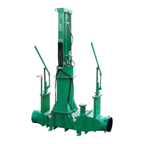
Description Main View Main View 3.5.1 Futuro Pump Legend: Hydraulic cylinder Grease lines Manual lever (guillotine valve) Reversing mechanism Pumping Tube Discharge guillotine valve Spring housing Access door Intake guillotine valve 10 Air drain pipe 11 Manual lever (guillotine valve) - Page 24 Description Main View Legend: Intake flapper valve Flapper door seal Downstroke lever Piston Discharge flapper valve Discharge valve spring 2007-9015-001 24 / 108 03-2014...
- Page 25 Description Main View 3.5.2 Hydraulic Power Unit Legend: Oil reservoir Reservoir cap Oil sight gauge Ball valve Oil filter Motor Chain joint guard Hydraulic Pump 2007-9015-001 25 / 108 03-2014...
- Page 26 Description Main View 3.5.3 Accessories and optional equipment Intake options Hopper A hopper is attached to the intake of the pump when the pump is to be fed by a gutter from a floor scraper or with a skid-steer loader. Various hopper models are available.
- Page 27 Description Main View Air flush In sand bedding operation, the air flush option is mandatory to push the sand out of the evacuation line. The evacuation line should be flushed periodically using air pressure only and/or air pressure and a straw bullet. If the top of the manure reservoir is higher than the cap on the air flush riser pipe, a gate valve must be installed to prevent manure flow into the air line.
- Page 28 Description Main View Guillotine valve configurations 12” [305 cm] valve 16” [406 cm] valve * Dimensions do not include lever extensions. If lever extensions are used, add the extension length to these dimensions. Manual lever and lever extension Manual lever Lever extension Available lengths 12”...
- Page 29 Description Main View Hydraulic guillotine valve (optional) Hydraulic cylinder hose Hydraulic cylinder adaptors Hydraulic cylinder hose adaptors Hydraulic guillotine control valve Pump and tank hoses Reversing valve hoses Selection valve Flapper valves Note! The flapper valve prevents manure flow back as long as manure remains consistent enough to seal the flapper.
-
Page 30: Technical Data
Description Technical Data Technical Data 3.6.1 Geometric data Futuro pump Hydraulic cylinder diameter 4” [102 mm] Length* 49” [124.5 cm] Width* 27½” [69.9 cm] Height* 140” [355.6 cm] Weight* 1422 lbs [645 kg] Intake diametre 16” [406 mm] Discharge diametre 12¾”... - Page 31 Description Technical Data 12¾” [315 mm] steel elbows 15° Elbow 30° Elbow 45° Elbow 60° Elbow 75° Elbow 90° Elbow 16” [406 mm] steel elbows 15° Elbow 30° Elbow 45° Elbow 60° Elbow 75° Elbow 90° Elbow 2007-9015-001 31 / 108 03-2014...
- Page 32 Description Technical Data 16” [406 mm] discharge pipe 5' [1.52m] needle 10' [3.05m] needle A 60” (1.52 m) A 120” (3.05 cm) B 48” (1,22 m) B 21” (53.3 cm) and less X 20° and more C 48” (1,22 m) X 15°...
- Page 33 Description Technical Data 75º long radius elbow with rising pipe 75º long radius elbow with rising pipe (15º X 15' long) (15º X 20' long) A 216” (5.49 m) A 276” (7.01 m) B 104” (2.64 m) B 120” (3.05 m) C 80”...
- Page 34 Description Technical Data 3.6.2 Performance data Futuro pump performance charts S.A.E. chart Slurry consistency Maximum Maximum length of evacuation distance suction pipe Normal 2” 600' Maximum 5” 200' Maximum evacuation line length* Varies based on manure consistency Maximum length of suction pipe**...
- Page 35 Description Technical Data Hydraulic Power Unit performance charts Max. Power unit configuration Flow rate Pressure Motor Freq. Pump PLP 20-14 20,7 1800 124,1 3.7 kW 50 Hz 1450 PLP 20-16 1440 99,3 PLP 20-20 30,3 1200 82,7 PLP 20-14 24,8 1500 103,4 PLP 20-16...
- Page 36 Description Technical Data 3.6.3 Electrical motor specifications Electrical data Rated Motor Voltage As per local requirements Frequency 50Hz or 60Hzas per local requirements Rated Motor Power 5HP to 7.5HP [3.7KW - 5.5KW] Rated Motor Speed 50Hz@1450rpm 60Hz@1760rpm Rated Motor Torque No special requirements Rated Motor Current No special requirements...
- Page 37 Description Technical Data 3.6.4 Control panel specifications The control panel must: ● comply with the following requirements: - 2006/95/CE directives (Electrical equipment designed for use within certain voltage limits) - 92/31/CEE directives (Electromagnetic compatibility) ● comply with the following harmonized standards: - EN 60204-1 (Safety of machinery - Electrical equipment of machines);...
- Page 38 Description Technical Data 3.6.6 Concrete anchor bolts specifications Bolt Diametre 3/8” [10mm] 1/2” [13mm] 3/4” [19mm] 3” 2 3/4” 3 3/4” 3 3/4” 5 1/2” Bolt Length (A) [76mm] [70mm] [95mm] [95mm] [140mm] Material Steel Steel Steel SS 304 Steel Minimum hole Hnom Hnom...
-
Page 39: Transport
Transport Permissible devices and aids for transportation Transport Special personnel qualification required for transport Transport may only be performed by specially qualified personnel in accordance with the safety instructions. Safety instructions for transport To prevent damage to property and/or life-threatening injury to personnel always observe the following: ●... -
Page 40: Lifting And Moving The Pump
Transport Information on disposing of packing material Lifting and moving the pump Using safety chains ● Attach safety chains to the lifting rings as illustrated below. ● To lift the pump in a vertical position, use the lifting rings located on the top of the pump. -
Page 41: Installation
Installation Safety instructions for installation Installation Special personnel qualification required for installation Installation may only be carried out by specially qualified personnel in accordance with the safety instructions. Safety instructions for installation Caution! When electrical motors and/or control panels come from a supplier other than the manufacturer, it is mandatory to verify components compatibility. -
Page 42: Assembly Preparations
Installation Assembly preparations Assembly preparations Necessary documents ● Electrical wiring diagrams ● Foundation plan Special tools Description Purpose Fork lift truck To lift the equipment Chain hoist To lift the equipment Safety chains To lift the equipment Hammer drill To make holes in the concrete floor Concrete drill bit To make holes in the concrete floor Hammer... - Page 43 Installation Assembly preparations Wrench set To tighten bolts and anchor bolts Ratchet tool set To tighten bolts and anchor bolts Allen wrenches To tighten set screws on pulleys Pulleys installation To tighten bolts and anchor bolts at Torque wrench the specified torque Local purchased items Provided by the owner: ●...
- Page 44 Installation Assembly preparations 5.3.1 Minimum pit dimensions for installing the pump in a service pit Attention! ● The minimum pit dimensions vary depending on the accessories that will be installed with the pump in the pit. ● Minimum dimensions of the pit do not include a stairway for pump maintenance.
- Page 45 Installation Assembly preparations Pit for pump with a hopper and with an air riser Refer to section on Installing a 6” [15 cm] riser for air flush The length of pit is applicable to all configurations of intake and discharge adaptors, with or without guillotine valve.
- Page 46 Installation Assembly preparations Pit for pump with a suction pipe and without an air riser The length of pit is applicable to all configurations of intake and discharge adaptors, with or without guillotine valve. 2007-9015-001 46 / 108 03-2014...
-
Page 47: Environmental Prerequisites For Setting Up
Installation Environmental prerequisites for setting up Pit for pump with a suction pipe and with an air riser Refer to section on Installing a 6” [15 cm] riser for air flush The length of pit is applicable to all configurations of intake and discharge adaptors, with or without guillotine valve. -
Page 48: Installing The Pump
Installation Installing the pump Installing the pump Warning! Always shut off and lock the power supply before installing the equipment. Caution! Never allow bystanders to stay close to the pump when it is lifted. Caution! Sharp edges may cause cuts. To install concrete anchor bolts properly, refer to the Technical Data Section on Concrete Anchor Bolt. - Page 49 Installation Installing the pump 5.5.2 Installing guillotine shut-off valves on the intake and discharge of the pump ● The lever is mounted parallel to the guillotine housing (perpendicular to the line). ● The lever can be rotated, in 90° increments, by re-assembling the upper bolt flange...
- Page 50 Installation Installing the pump 5.5.4 Installing a suction pipe through a wall (pump in a service pit) Attention! In sand bedding operations, the suction pipe must be turned down with hydraulic agitation option added to prevent plugging. Refer to section on Minimum pit dimensions for installing the pump in a service pit The maximum length of the suction line is based upon the manure consistency.
- Page 51 Installation Installing the pump 5.5.5 Installing a hydraulic agitator on the suction pipe Attention! For a safe handling when installing the hydraulic agitator, use a lifting equipment having a minimum capacity of 200 lbs (90 kg) to hold the hydraulic agitator. ●...
-
Page 52: Installation Of The Evacuation Line
Installation Installation of the evacuation line Installation of the evacuation line Inspection of the steel pipes before installation Make sure the steel pipes have not been damaged during transportation. Note! If some pipe ends are out of shape, use a hydraulic jack to correct them. - Page 53 ● To withstand the pressure of manure inside the line. Types of evacuation pipe joints GEA Houle manufactures 8 different types of joints for quick assembly of PVC and steel pipes. GEA Houle joints cannot dislocate when properly installed. The installer who chooses to use concrete thrust blocks must refer to local authorities for proper specifications regarding the size, the orientation and the spacing of the blocks.
- Page 54 Installation Installation of the evacuation line Male PVC to female PVC Male PVC to male PVC Male steel to female PVC Male steel to male PVC Male steel to male steel Male steel to female steel** Male PVC to female SS* Male steel to female SS* Legende: PVC pipe collar...
- Page 55 5.6.1 Installing a discharge pipe on the end of the evacuation line Refer to section on Dimensions of GEA Houle steel components prior to install the discharge pipe. ● Install the discharge pipe in the bottom of the manure storage pit according to the model.
- Page 56 Installation Installation of the evacuation line 5.6.2 Installing a flapper valve on the end of the evacuation line ● Install the flapper valve in the bottom Manure storage pit of the manure storage pit. ● The flapper valve prevents manure flow back as long as manure remains consistent enough to seal the flapper.
- Page 57 Installation Installation of the evacuation line ● Remove the filling cap of each insulated gate valve and fill the tube with hydraulic oil to protect it against frost and to prevent corrosion. Then put the cap back on. Filling cap 2007-9015-001 57 / 108 03-2014...
- Page 58 Installation Installation of the evacuation line 5.6.3 Installing a 6” [15 cm] riser for air flush ● The riser is mandatory in sand Air riser bedding operations to flush sand from the evacuation line using air pressure and a straw bullet. Evacuation line ●...
- Page 59 Installation Installation of the evacuation line Flush valve ● The flush valve must Relief valve connected to an air tank. ● All connections to the valves on the air riser cap should be made with flexible hoses to allow removal of the cap.
- Page 60 Installation Installation of the evacuation line 16” [406 mm] evacuation line Length of evacuation line. 110' 140' 170' 200' 230' 260' 290' 320' 350' Pressure 15 m 25 m 34 m 52 m 60 m 70 m 79 m 88 m 98 m 107 m Minimum size of air tank...
- Page 61 The steel evacuation line, as well as the Futuro pump, can be protected against corrosion by installing sacrificial anodes at specific points along the buried line.
- Page 62 Installation Installation of the evacuation line Insure fully dedicated protection from the sacrificial anodes: ● To prolong the life of the anodes, it is imperative that they only protect the pump and the evacuation line. ● At the time of installation, you must ensure that no ground wire is attached directly or indirectly to the equipment protected.
- Page 63 Installation Installation of the evacuation line Connection of sacrificial anode Attention! Anodes must be connected and activated before they are buried. Hardware supplied with each sacrificial anode: 1 - ¾-10 NC x 2” [19 mm X 5 cm] ..bolt 2 - ¾”...
- Page 64 Installation Installation of the evacuation line Space the anodes along the evacuation line as shown. Anodes Activation of the sacrificial anode Attention! Discard any plastic film that may have been wrapped around the anode cardboard tube for handling. Do not remove the plastic caps from the cardboard tube.
-
Page 65: Installing The Motor On The Hydraulic Power Unit
Installation Installing the motor on the hydraulic power unit Installing the motor on the hydraulic power unit Warning! Always shut off and lock the power supply before installing the equipment. Warning! Always put back in place the safety guard before starting the equipment. - Page 66 Installation Installing the motor on the hydraulic power unit Note! In order to fit with the selected motor, it may be necessary to readjust the hydraulic pump position. To readjust it, use appropriate shims and bolt patterns. 2 bolt patterns have been designed on the motor support.
-
Page 67: Installing The Hydraulic Power Unit
Attention! If there is an electrical interlock in the connection of the different components of the Futuro pump or if these components are connected to a central control panel, any of these machine can start automatically. The owner must have all the machine connected in a lockable main switch. - Page 68 Installation Installing the hydraulic power unit Positioning the power unit ● Install the hydraulic power unit in a location that will be protected from freezing temperatures. ● Choose a location that will minimize the length of hydraulic lines required. ● Allow sufficient clearance around the hydraulic unit to permit service and routine maintenance as well as ventilation to prevent overheating.
- Page 69 Installation Installing the hydraulic power unit Hydraulic line installation guidelines Refer to section on hydraulic diagram. Proper hydraulic hose installation is essential for satisfactory system performance and ensuring the maximum service life from the hose. Hose assemblies will flex and change in length due to fluid pressure changes and temperature.
-
Page 70: Connecting The Futuro To The Hydraulic Power Unit
Connecting the Futuro to the hydraulic power unit ● Using orange hydraulic hoses from the power unit, connect the Futuro reversing valve. ● Once connected, make sure 2 ball valves under the power unit are opened to allow oil circulation. -
Page 71: Initial Commissioning
Initial Commissioning Safety instructions for initial commissioning Initial Commissioning Special personnel qualification required for initial commissioning Initial commissioning may only be performed by specially qualified personnel in accordance with the safety instructions. Safety instructions for initial commissioning Caution! Always open 2 ball valves under the hydraulic power unit before operating the equipment. -
Page 72: Checks Before Initial Commissioning
Initial Commissioning Checks before initial commissioning Checks before initial commissioning The owner should ensure that: ● Each point of the warranty registration form have been met. ● Oil in the hydraulic power unit tank is at proper level. ● 2 ball valves under hydraulic power unit have been opened. ●... - Page 73 Initial Commissioning Checks before initial commissioning Hydraulic lines ● Confirm that all hydraulic line connections are correct and tight. ● Confirm that all hydraulic lines are properly supported and secured. Pump ● Clean and lubricate the reversing Adjustable finger mechanism with fine oil; ●...
- Page 74 Initial Commissioning Checks before initial commissioning Verification of the reversing mechanism Attention! Beware of reversing mechanism moving parts. Note! These steps apply only to reversing valves that are adjustable height wise. Spacers trigger reversing mechanism in the up position, then Bolts check by hand if the spool of the reversing valve moves up and down...
-
Page 75: First Start
Handing over to the owner Hand-over warranty registration form The warranty registration form must be completed and signed by the customer and the dealer. The warranty registration form must be returned back to GEA Houle Inc. to validate the warranty. 2007-9015-001... -
Page 76: Operation
Operation Safety instructions for operation Operation Special personnel qualification required for operation Operation may only be performed by specially qualified personnel in accordance with the safety instructions. The operator may only carry out work on the equipment if trained, instructed and authorized to do so by the owner. - Page 77 Operation Safety instructions for operation Carry out the following checks before every start: ● Check and make sure that all of the safety devices (safety guard, emergency-off switches, etc.) are present and working. ● Check the product for visible damage; immediately repair without any delay damage found (note: personnel qualification required) or send to the specialist dealer - the product may only be used if in perfect condition.
-
Page 78: Description Of The Operating Elements
Operation Description of the operating elements Description of the operating elements Note! The primary operating element for a Futuro pump is the control. (see Control Panel Operator's Manual for details); 7.3.1 Manual lever guillotine valve Manual lever Open ● Raise the lever to open the valve. - Page 79 Operation Description of the operating elements 7.3.3 Evacuation line air flush risers The air flush valve and pressure relief Flush valve valves are ball type valves. Relief ● The handle rotates 90°. valve Close ● The valve is closed when the handle is near to the line.
-
Page 80: Operating
Operation Operating Operating The Futuro pump may be operated: ● automatically by controlled time settings of the control panel. ● manually by an operator. 7.4.1 Normal operation Note! If there less than the equivalent of 30 days of manure accumulated above the evacuation line discharge at the beginning of winter, severe cold can completely freeze the manure pile and stop the pump. - Page 81 Operation Operating 7.4.2 Air flush procedure for the evacuation line. ● Stop the pump and close the Flush valve discharge guillotine valve; Relief ● Close the gate valve on the riser; valve Close ● Relieve gas pressure in the riser by opening the relief valve;...
- Page 82 Operation Operating 7.4.3 Air flush procedure for the suction line. Note! Flushing the suction pipe is only required to clear obstructions that have clogged the suction pipe. ● Stop the pump and close the intake guillotine valve; ● Open the air injection valve for 10 seconds; ●...
-
Page 83: Operating Faults
Operating faults Safety instructions for troubleshooting Operating faults If necessary, please contact your nearest authorized technical dealer. Special personnel qualification required for troubleshooting Troubleshooting may only be performed by specially qualified personnel in accordance with the safety instructions. Safety instructions for troubleshooting To prevent damage to property and/or life-threatening injury to personnel always follow these instructions: ●... -
Page 84: Troubleshooting Possible Faults
Operating faults Troubleshooting possible faults Troubleshooting possible faults Futuro pump Symptom Possible cause Remedy Pump is not running. Power supply has been Check all circuit breakers and fuses disconnected to the hydraulic Check that all wire connections are power unit. - Page 85 Operating faults Troubleshooting possible faults Hydraulic fluid Symptom Possible cause Remedy Hydraulic fluid is dirty. Fluid and/or filters not serviced Perform a fluid and filter at the proper intervals. change. Incompatible fluids mixed in Do not top off the fluid level if the system.
- Page 86 Operating faults Troubleshooting possible faults Symptom Possible cause Remedy Loss of output pressure at Leak in the discharge line to the Repair or replace the defective the pump. pressure filter. part. Worn pump. Replace the pump. Unusually short pump Fluid and/or filters not serviced Perform a fluid and filter change.
-
Page 87: Maintenance
Maintenance Safety instructions for maintenance Maintenance If necessary, please contact your nearest authorized technical dealer. Special personnel qualification required for maintenance work Maintenance work may only be performed by qualified personnel in accordance with the safety instructions. Safety instructions for maintenance Danger! As manure produces toxic gases that may cause death, it is imperative to follow the safety instructions below before servicing the equipment:... - Page 88 Maintenance Safety instructions for maintenance To prevent damage to property and/or life-threatening injury to personnel always follow these instructions: ● Only use original spare parts / original wearing parts / original accessories. In the case of products by other manufacturers it cannot be ensured that they have been designed and produced from the point of view of loads and safety.
- Page 89 Maintenance Safety instructions for maintenance Special risks involved in maintenance work: ● Serious damage to property might occur if wrong replacement or wearing parts are installed. ● If energy sources are switched on unintentionally, this may lead to serious bodily injury or damage to property. ●...
-
Page 90: Scheduled Maintenance Responsibilities
Maintenance Scheduled maintenance responsibilities Scheduled maintenance responsibilities Interval Description Action (by) Check the oil level Check / fill On regular basis above pump piston (Operator) Lubricate the Lubricate Every 50 hours of equipment (Operator) operation Operate Operate gate valves weekly (Operator) Every 100 hours of Check the hydraulic... - Page 91 Maintenance Scheduled maintenance responsibilities 9.3.1 On regular basis Check the oil level above pump piston Note! Use biodegradable oil. Refer to section on Lubricant specifications. ● Make sure the oil above the pump piston is at proper level. ● Add oil as needed. 2”...
- Page 92 Maintenance Scheduled maintenance responsibilities ● Use grease zerks to lubricate the Grease zerks flapper door pivot of the Futuro pump. Operate gate valves ● Operate the gate valves to ensure Open they open and close easily. Closed 2007-9015-001 92 / 108...
- Page 93 Maintenance Scheduled maintenance responsibilities 9.3.3 Every 100 hours Check the hydraulic power unit oil level Note! Use hydraulic oil. Refer to section on Lubricant specifications. ● Ensure the oil reservoir of the hydraulic power unit is 2/3 full. Oil sight gauge ●...
- Page 94 Maintenance Scheduled maintenance responsibilities 9.3.5 Every 3000 hours or yearly Change oil of hydraulic power unit Caution! Ball valves under the reservoir can only be closed for servicing when the power supply have been turned off. When servicing is done, always keep these 2 ball valves opened to avoid damage and/or injuries.
- Page 95 2000 psi [105 bar]. Only use cold water when cleaning with a pressure washer. Keep the pressure washer nozzle at least 12” [30 cm] from the surface to be cleaned. ● Clean the Futuro pump with a pressure washer; ● Clean...
- Page 96 Maintenance Scheduled maintenance responsibilities Check insulated gate valve oil level Note! Use hydraulic oil. Refer to section on Lubricant specifications. ● Remove the filling cap of the Filling cap insulated gate valve. ● Fill up the tube up with hydraulic oil. ●...
- Page 97 Maintenance Scheduled maintenance responsibilities Check the evacuation chamber and flappers Attention! Before opening the side doors of the evacuation chamber, make sure to loosen the 4 bolts with care on top of the spring housing in order to relieve tension on the discharge flapper. Attention! Take care when loosing the bolts.
-
Page 98: Decommissioning
Decommissioning Temporary decommissioning Decommissioning 10.1 Special personnel qualification required for decommissioning Decommissioning may only be performed by specially qualified personnel in accordance with the safety instructions. 10.2 Safety instructions for decommissioning To prevent damage to property and/or life-threatening injury to personnel always follow these instructions: ●... -
Page 99: Final Decommissioning/Disposal
Decommissioning Final decommissioning/disposal Lubricate the equipment Note! Use general purpose grease Refer to section on Lubricant specifications. ● Grease all parts labeled with; Refer to section on Label position ● To prevent corrosion, spread all moving parts with an environmentally friendly anti-corrosion product;... -
Page 100: Appendix
● After 1 minute of rest, measure the thickness of slurry at the center of the disc. 11.2 Label position Futuro pump Hydraulic power unit C, F C, F D, G D, G I, L... - Page 101 Appendix Label position Air riser cap Q, R US + EU 2099-4720-010 2010-4700-400 2099-4721-010 US + EU 2099-4724-010 2099-4725-190 2099-4701-240 US + EU 2099-4725-130 2099-4721-000 2005-4703-560 2099-4724-030 2099-4725-420 2099-4725-240 US + EU US + EU 2099-4700-390 2099-4725-360 2099-4725-470 2099-4725-460 2099-4721-120 US = American label / EU = European label 2007-9015-001 101 / 108...
-
Page 102: Hydraulic Diagrams
Appendix Hydraulic diagrams 11.3 Hydraulic diagrams 11.3.1 Futuro pump Pump cylinder Reversing valve 2007-9015-001 102 / 108 03-2014... - Page 103 Appendix Hydraulic diagrams 11.3.2 Futuro pump with guillotine valve option Guillotine valve Pump cylinder cylinder Guillotine valve Reversing valve Selection valve 2007-9015-001 103 / 108 03-2014...
- Page 104 Appendix Hydraulic diagrams Legend: Hydraulic reservoir Shut-off valves Oil filter Hydraulic pump Selector valve Reversing valve Power unit Optional cylinder on guillotine Cylinder on guillotine valve 10 Control valve 2007-9015-001 104 / 108 03-2014...
- Page 105 Appendix Hydraulic diagrams 11.3.3 Futuro with optional hydraulic agitator Pump cylinder Reversing valve Hydraulic agitator motor 2007-9015-001 105 / 108 03-2014...
-
Page 106: Abbreviations
Appendix Abbreviations 11.4 Abbreviations Units Explanation Units Explanation Amp (current) Pounds Liters per minute CE/ EC European Union Minute Centimeters Meter ° Degrees (angles) Millimeters °C Centigrade/ Celsius Alloy Steel (temperature) °F Fahrenheit (temperature) Heat Treated Facsimile Low Carbon Steel ' (ft) Feet Medium Carbon Steel... - Page 107 Appendix Abbreviations 2007-9015-001 107 / 108 03-2014...
- Page 108 Excellence • Passion • Integrity • Responsibility • GEA-versity GEA Group is a global engineering company with multi-billion euro sales and operations in more than 50 countries. Founded in 1881, the company is one of the largest providers of innovative equipment and process technology.
Need help?
Do you have a question about the Futuro and is the answer not in the manual?
Questions and answers
Lately the flapper valves haven’t been moving….i move them manually and it works for awhile but then stop again ….its 7 years old and i grease them once a month…manure is quite liquid…100 cow herd