
Related Manuals for Endress+Hauser Flowphant T DTT31 Flowphant T DTT35


Summary of Contents for Endress+Hauser Flowphant T DTT31 Flowphant T DTT35
- Page 1 Products Solutions Services BA00235R/09/EN/17.18 71415550 2018-02-15 Valid as of version 01.00 (device version) Operating Instructions Flowphant T DTT31, DTT35 Flow switch...
-
Page 3: Table Of Contents
Accessories ....31 10.1 Device-specific accessories ... . 31 10.2 Communication-specific accessories . . . 34 Endress+Hauser... -
Page 4: About This Document
Symbols for certain types of information Symbol Meaning Permitted Procedures, processes or actions that are permitted. Preferred Procedures, processes or actions that are preferred. Forbidden Procedures, processes or actions that are forbidden. Indicates additional information. Reference to documentation. Reference to page. Reference to graphic. Endress+Hauser... -
Page 5: Basic Safety Instructions
Follow instructions and comply with basic conditions. The operating personnel must fulfill the following requirements: ‣ Are instructed and authorized according to the requirements of the task by the facility' s owner-operator. ‣ Follow the instructions in this manual. Endress+Hauser... -
Page 6: Designated Use
Use only original spare parts and accessories from the manufacturer. Product safety This measuring device is designed in accordance with good engineering practice to meet state- of-the-art safety requirements, has been tested, and left the factory in a condition in which it is safe to operate. Endress+Hauser... -
Page 7: It Security
(www.endress.com/deviceviewer): all data relating to the device and an overview of the Technical Documentation supplied with the device are displayed. The nameplate illustrated below is designed to help users identify specific product information, such as the serial number, design, variables, configuration and device approvals: Endress+Hauser... -
Page 8: Storage And Transport
Pack the device so that it is reliably protected against impact when it is stored (and transported). The original packaging offers the best protection. Storage temperature –40 to +85 °C (–40 to +185 °F) Installation Installation conditions 4.1.1 Dimensions → 38 Endress+Hauser... - Page 9 Always install the device at the wrench flats. ‣ Use a suitable open-ended wrench → 9. ‣ The local display can be rotated electronically by 180 °→ 14. ‣ The top housing section can be rotated mechanically by up to 310 °. Endress+Hauser...
- Page 10 NOTICE If the device is installed incorrectly this can result in incorrect measurements! ‣ Do not install in down pipes open towards the end. ‣ The sensor tip should never touch the pipe wall. A0006978 4 Incorrect installation! Endress+Hauser...
- Page 11 No recesses, folds or gaps Honed and polished surface, Ra ≤ 0.76 µm (30 µin) Pay attention to the following when installing the thermometer to ensure that the cleanability is not affected: Comply with the requirements of the 3-A Standard. Endress+Hauser...
-
Page 12: Electrical Connection
90° elbow or T-piece Pump Control valve 2x 90° elbow, 2- or 3-dimensional Electrical connection Connection conditions 5.1.1 DC voltage version with M12x1 connector DTT35: According to the 3-A Standards electrical connecting cables must be smooth, corrosion-resistant and easy to clean. Endress+Hauser... - Page 13 The sensor tip of the device heats up once the device is connected to the power supply! The temperature can increase to approx. 90 °C (194 °F). ‣ As the device sensor tip heats up, appropriate protective clothing must be worn! Endress+Hauser...
-
Page 14: Operation Options
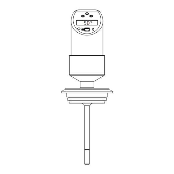
Flow switch with M16x1.5 valve connector or NPT ½" Item No. Output setting 1x PNP switch output Operation options Overview of operation options The device is operated via three keys. The digital display and the light emitting diodes (LED) assist navigation through the operating menu. Endress+Hauser... - Page 15 Red = error/fault Yellow LEDs for switching states LED red/green blinking = warning LED on = switch closed LED off = switch open Communication jack for personal computer A0020825-EN 9 Position of the operating elements and possibilities for display Endress+Hauser...
-
Page 16: Structure And Function Of The Operating
To display the prompt to save data (press + or − to select the option "YES" or "NO"), confirm with the E key. If "YES" is selected when asked to save the data, changes are made to the parameter settings. Endress+Hauser... - Page 17 1 %with the + or - key (factory setting 0). Select the "WAIT" function with the E key. Accept (' l earn' ) the current measured value after approx. 10 s- "OK" appears on the display. Endress+Hauser...
- Page 18 Or: The message "W432" or "NOK" appears on the display after 60 s. W432: A sufficiently stable flow could not be detected during the learning process. The system takes an average of the 10 values last measured during the learning process. Endress+Hauser...
- Page 19 (RSP). The device is still operative if message "W432" or "NOK" is displayed. There can be large deviations at the switch point, however. Recommendation: Repeat the learning process (points 1 to 4) until "OK" appears on the display. Endress+Hauser...
- Page 20 WAIT LOWF FUNC HYNC HYNO WAIT TRSP OUT2 MODE FLOW TEMP (optional) UNIT °C °F FNC2 HYNC HYNO SP2L WAIT RSP2 TSP2 TRSP2 SERV LOCK CODE PRES REV’C LST’A OPEN CLOS SIM2 OPEN CLOS A0005784 13 Operating menu Endress+Hauser...
- Page 21 °F WAIT LOWF WAIT 4-20 MODE FLOW TEMP HOLD FCUR MODE FLOW TEMP UNIT °C °F FUNC HYNC HYNO WAIT TRSP SERV LOCK CODE PRES REV’C LST’D SIMA OPEN CLOS A0006819 14 Operating menu Function groups Functions Settings Endress+Hauser...
- Page 22 Setting for the maximum flow rate that Calibration WAIT occurs. 100 % value → 11, 17 LOWF Learn Low Flow Setting for the maximum flow rate that WAIT occurs. 0 % value → 11, 17 Endress+Hauser...
- Page 23 Factory setting: 50 % Or optionally for SP2: Enter value –15 to +85 °C (–5 to +185 °F) in increments of 1 °C (1 °F) if the switching mode MODE is set to temperature TEMP. Factory setting: 55 °C Endress+Hauser...
- Page 24 Output 2 TEMP TEMP: temperature Factory setting: temperature (TEMP) UNIT Technical unit Temperature unit selection (°C or °F) Function is only visible if the switching mode MODE is set to temperature TEMP in the 2nd output. Factory setting: °C Endress+Hauser...
- Page 25 Locking code Enter the device locking code. Service functions Code Change locking User-defined numerical code 1 to 9 999 code 0= no locking Only visible if the locking code is valid. PRES Reset Reset all entries to the delivery settings. Endress+Hauser...
-
Page 26: Access To The Operating Menu Via The Operating Tool
Simulation values for analog output in mA (3.5/4.0/8.0/12.0/16.0/20.0/21.7) Access to the operating menu via the operating tool A0008072 16 Operation, visualization and maintenance with PC and configuration software PC with FieldCare configuration software Configuration kit TXU10-AA or FXA291 with USB port Flow switch Endress+Hauser... -
Page 27: Diagnostics And Troubleshooting
A flashing red/green status LED signals a warning. The display shows: • An E-code in the event of errors The measured value is uncertain if an error occurs. • A W-code in the event of warnings The measured value is reliable if warnings occur. Endress+Hauser... - Page 28 Check output wiring W432 Values for High Flow (HIF) or Low Flow (LOWF) could not be Set the High and Low Flow again (keep flow determined with certainty. The device can still be operated, velocity constant!) however. → 17 Endress+Hauser...
-
Page 29: Firmware History
11.08 HIF (70 to 100%) and LOWF (0 to 20%); warning message W200 12.2006 01.00.03 BA235r/09/en/ 71036990 10.07 12.2006 01.00.03 Analog output BA235r/09/en/ 71036990 version (4 to 20 mA) 12.06 available 02.2006 01.00.00 Original firmware BA218r/09/en/ 71022232 02.06 Endress+Hauser... -
Page 30: Maintenance
Disposal The device contains electronic components and must, therefore, be disposed of as electronic waste in the event of disposal. When disposing, comply with national disposal regulations, and separate and recycle the device components based on the materials. Endress+Hauser... -
Page 31: Accessories
• Collar welding boss movable with sealing taper, washer G½” and pressure screw G½" • Material of parts in contact with the process: 316L, PEEK, • Max. process pressure 10 bar (145 psi) • Order number: 51004752 (0.24) 30 (1.18) A0020710 18 Dimensions in mm (in) Endress+Hauser... - Page 32 • Movable clamping ring, various process connections 6 (0.24) • Material of compression fitting and parts in contact with the process: 316L • Order number: TA50-..(depending on the process connection) AF14 AF27 G½” A0020174-EN 20 Dimensions in mm (in) Endress+Hauser...
- Page 33 SS316 clamping ring: can only be used once. Once released the compression fitting cannot be repositioned on the thermowell. Fully adjustable immersion length on initial installation PTFE/Silopren ® clamping ring: can be reused, once released the fitting can be moved up and down the thermowell. Fully adjustable immersion length Endress+Hauser...
-
Page 34: Communication-Specific Accessories
• Order number: 51005148 1 (BN) + Core colors: 2 (WH) nc • 1 = BN brown 3 (BU) - • 2 = WH white 4 (BK) nc • 3 = BU blue A0020723 • 4 = BK black Endress+Hauser... -
Page 35: Technical Data
10.2.3 Configuration software The FieldCare ' D evice Setup' configuration programs can be downloaded free of charge from the Internet at: www.products.endress.com/fieldcare FieldCare ’Device Setup’ can also be ordered from an Endress+Hauser sales office. Technical data 11.1 Output 11.1.1 Signal on alarm... -
Page 36: Power Supply
< 100 mA (no-load) at 24 V , max. 150 mA (no-load); with reverse polarity protection 11.3 Environment 11.3.1 Ambient temperature range –40 to +85 °C (–40 to +185 °F) 11.3.2 Storage temperature –40 to +85 °C (–40 to +185 °F) Endress+Hauser... -
Page 37: Process
The maximum process pressure for the conical metal-metal process connection (MB option) for the device is 1.6 MPa = 16 bar (232 psi). 11.4.3 Flow limit Liquids: 0 to 3.0 m/s (0 to 9.84 ft/s) 11.4.4 Operational range Liquids: 0.03 to 3.0 m/s (0.1 to 9.84 ft/s) Endress+Hauser... -
Page 38: Mechanical Construction
38.5 (1.52) 24 (0.95) 36 (1.42) 6 (0.24) 6 (0.24) 6 (0.24) A0005279 All dimensions in mm (in) L = insertion length M12x1 connector as per IEC 60947-5-2 Valve connector M16x1.5 or NPT ½" as per DIN 43650A/ISO 4400 Endress+Hauser... - Page 39 • 50 mm (1.97 in) ANSI NPT ½" (1 = AF27) • 100 mm (3.94 in) Threaded process connection, inches, • 12 mm (0.47 in) cylindrical as per ISO 228: • 14 mm (0.55 in) G¼" (2 = AF14) G½" (2 = AF27) Endress+Hauser...
- Page 40 L1 = 14 mm (0.55 in). Suitable welding boss available as an accessory. 316L DIN 11851, DN25, PN40 (including coupling nut), 3-A marked and EHEDG-certified (only with 316L self-centering sealing ring, as per EHEDG position paper) Endress+Hauser...
-
Page 41: Certificates And Approvals
• EHEDG certification, TYPE EL CLASS I. Permitted process connections in accordance with EHEDG, see ' P rocess connections' section → 39 • 3-A Authorization No. 1144. 3-A Sanitary Standard. Permitted process connections in accordance with 3-A, see also "Process connections" section • 3-A marked process connections → 40 Endress+Hauser... -
Page 42: Supplementary Documentation
Supplementary documentation 11.7.1 Technical Information • Easy Analog RNB130: TI120R/09/en • Process display unit RIA452: TI113R/09/en • Universal data manager Ecograph T: TI01079R/09/en • Data logger Minilog B: TI089R/09/en 11.7.2 Operating Instructions Flow switch Flowphant T DTT31, DTT35: BA00235R/09/en Endress+Hauser... - Page 44 www.addresses.endress.com...
Need help?
Do you have a question about the Flowphant T DTT31 Flowphant T DTT35 and is the answer not in the manual?
Questions and answers