Table of Contents
Advertisement
Quick Links
KA01411F/00/EN/03.22-00
71566285
2022-04-05
Products
Brief Operating Instructions
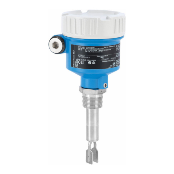
Liquiphant FTL41
Vibronic
Point level switch in liquids
These Instructions are Brief Operating Instructions; they are
not a substitute for the Operating Instructions pertaining to
the device.
Detailed information about the device can be found in the
Operating Instructions and the other documentation:
Available for all device versions via:
• Internet:
www.endress.com/deviceviewer
• Smart phone/tablet: Endress+Hauser Operations App
Solutions
Services
Advertisement
Table of Contents

Related Manuals for Endress+Hauser Liquiphant FTL41


Summary of Contents for Endress+Hauser Liquiphant FTL41
- Page 1 Operating Instructions pertaining to the device. Detailed information about the device can be found in the Operating Instructions and the other documentation: Available for all device versions via: • Internet: www.endress.com/deviceviewer • Smart phone/tablet: Endress+Hauser Operations App...
-
Page 2: Associated Documentation
Associated documentation Liquiphant FTL41 Associated documentation Order code: XXXXX-XXXXXX Ser. no.: XXXXXXXXXXXX Ext. ord. cd.: XXX.XXXX.XX Serial number www.endress.com/deviceviewer Endress+Hauser Operations App A0023555 About this document Symbols 2.1.1 Safety symbols DANGER This symbol alerts you to a dangerous situation. Failure to avoid this situation will result in serious or fatal injury. - Page 3 Liquiphant FTL41 About this document This symbol alerts you to a dangerous situation. Failure to avoid this situation can result in serious or fatal injury. CAUTION This symbol alerts you to a dangerous situation. Failure to avoid this situation can result in minor or medium injury.
-
Page 4: Basic Safety Instructions
Basic safety instructions Liquiphant FTL41 Basic safety instructions Requirements for the personnel The personnel must fulfill the following requirements to carry out the necessary tasks, e. g., commissioning and maintenance: ‣ Trained, qualified specialists must have a relevant qualification for the specific function and task ‣... -
Page 5: Product Safety
It meets the general safety standards and legal requirements. It also complies with the EU directives listed in the device-specific EU Declaration of Conformity. Endress+Hauser confirms this by affixing the CE mark to the device. Incoming acceptance and product identification... -
Page 6: Product Identification
All of the information on the measuring device is displayed along with an overview of the scope of technical documentation provided. • Enter the serial number on the nameplate into the Endress+Hauser Operations app or scan the 2-D matrix code on the nameplate with the Endress+Hauser Operations app 4.2.1... -
Page 7: Mounting Requirements
Liquiphant FTL41 Mounting A0036954 1 Installation examples for a vessel, tank or pipe Mounting requirements 5.1.1 Take switch point into consideration The following are typical switch points, depending on the orientation of the point level switch. Water +23 °C (+73 °F) Minimum distance between the fork tip and the tank wall or pipe wall: 10 mm (0.39 in) - Page 8 Mounting Liquiphant FTL41 5.1.2 Take viscosity into consideration Viscosity values • Low viscosity : < 2 000 mPa⋅s • High viscosity: > 2 000 to 10 000 mPa⋅s Low viscosity It is permitted to position the tuning fork within the installation socket. > 25 (0.98) A0033297 ...
- Page 9 Liquiphant FTL41 Mounting 5.1.3 Avoid buildup A0033239 5 Installation examples for a highly viscous process medium 5.1.4 Take clearance into consideration A0033236 6 Take clearance outside the tank into consideration Endress+Hauser...
- Page 10 Mounting Liquiphant FTL41 5.1.5 Support the device Support the device in the event of severe dynamic load. Maximum lateral loading capacity of the pipe extensions and sensors: 75 Nm (55 lbf ft). A0031874 7 Examples of support in the event of dynamic load Marine approval: In the case of pipe extensions or sensors longer than 1 600 mm, a support is needed at least every 1 600 mm.
-
Page 11: Mounting The Device
Liquiphant FTL41 Mounting Mounting the device 5.2.1 Required tool • Open-ended wrench for sensor installation • Allen key for housing locking screw 5.2.2 Installation Aligning the tuning fork using the marking A0039125 9 Markings to align the tuning fork Installing in pipes •... - Page 12 Mounting Liquiphant FTL41 Screwing in the device • Turn by the hex bolt only, 15 to 30 Nm (11 to 22 lbf ft) • Do not turn at the housing! A0034852 11 Screwing in the device Aligning the cable entry 4 3.5 Nm...
-
Page 13: Electrical Connection
Liquiphant FTL41 Electrical connection Electrical connection Required tool • Screwdriver for electrical connection • Allen key for screw of cover lock Connecting requirements 6.2.1 Cover with securing screw In the case of devices for use in the hazardous area with a certain type of protection, the cover is sealed by a securing screw. - Page 14 Electrical connection Liquiphant FTL41 6.3.1 3-wire DC-PNP (electronic insert FEL42) • Three-wire DC version • Switches the load via the transistor (PNP) and separate connection, e.g. in conjunction with programmable logic controllers (PLC), DI modules according to EN 61131-2 Supply voltage WARNING Failure to use the prescribed power unit.
- Page 15 Liquiphant FTL41 Electrical connection Terminal assignment 350 mA U = 10...55 V DC I max: 350 mA 55 V >0,7 >0,5 4 3 1 0.5 A A0036056 14 Terminal assignment FEL42 Terminal assignment at electronic insert Terminal assignment at M12 plug according to EN61131-2 standard...
- Page 16 Electrical connection Liquiphant FTL41 Behavior of the switch output and signaling (L–) ΔU <100 µA (L–) (L–) ΔU <100 µA (L–) <100 µA (L–) A0033508 15 FEL42 switching behavior, signaling LED MAX DIP switch for setting the MAX safety...
- Page 17 Liquiphant FTL41 Electrical connection Power consumption S < 25 VA, P < 1.3 W Connectable load Loads switched via 2 potential-free changeover contacts (DPDT) • I ≤ 6 A (Ex de 4 A), U~ ≤ AC 253 V; P~ ≤ 1 500 VA, cos φ = 1, P~ ≤ 750 VA, cos φ > 0.7 •...
- Page 18 Electrical connection Liquiphant FTL41 Terminal assignment >0,7 U = 19...55 V DC >0,5 U 19...253 V AC 0.5 A A0036057 16 Universal current connection with relay output, electronic insert FEL44 When bridged, the relay output works with NPN logic...
- Page 19 Liquiphant FTL41 Electrical connection Behavior of the switch output and signaling A0033513 17 FEL44 switching behavior, signaling LED MAX DIP switch for setting the MAX safety MIN DIP switch for setting the MIN safety LED red for alarm LED yellow, switch status GN LED green, operational status, device on 6.3.3...
- Page 20 Electrical connection Liquiphant FTL41 Behavior output signal • OK state: Current 2.2 to 3.8 mA • Demand mode: Current 0.4 to 1.0 mA • Alarm: Current 0.4 to 1.0 mA Terminal assignment IEC 60947-5-6 8,2 V DC NAMUR – >0,7 >0,5...
- Page 21 Liquiphant FTL41 Electrical connection Behavior of the switch output and signaling 2.2...3.8 mA 0.4...1.0 mA 2.2...3.8 mA 0.4...1.0 mA < 1.0 mA A0037694 19 FEL48 switching behavior and signaling MAX DIP switch for setting the MAX safety MIN DIP switch for setting the MIN safety...
-
Page 22: Overview Of Operation Options
Operation options Liquiphant FTL41 24/25 mm 8.0 Nm A0018023 20 Example of coupling with cable entry, electronic insert with terminals M20 coupling (with cable entry), example Conductor cross-section maximum 2.5 mm (AWG14), ground terminal on inside in housing + terminals on the electronics Conductor cross-section maximum 4.0 mm... -
Page 23: Function Check
Liquiphant FTL41 Commissioning 7.1.2 Elements on the electronic insert 1 2 3 >0,7 U = 19...55 V DC >0,5 U 19...253 V AC A0039317 21 Example of electronic insert FEL44 LED red, for warning or alarm LED yellow, switch status LED green, operational status (LED green lights up = device on) DIP switch to set the density to 0.7 or 0.5... - Page 24 *71566285* 71566285 www.addresses.endress.com...
Need help?
Do you have a question about the Liquiphant FTL41 and is the answer not in the manual?
Questions and answers