
Related Manuals for Endress+Hauser Soliswitch FTE20


Summary of Contents for Endress+Hauser Soliswitch FTE20
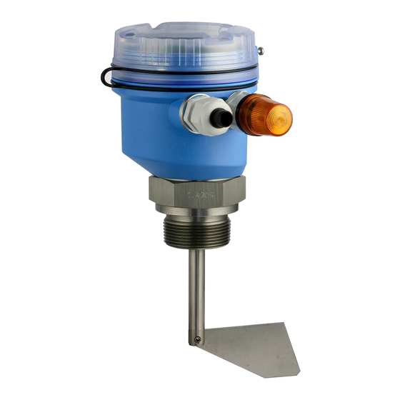
- Page 1 Operating Instructions Soliswitch FTE20 Point level switch BA01069F/09/EN/01.12 71186553...
-
Page 3: Table Of Contents
Soliswitch FTE20 Table of contents Table of contents Important document information ... . . 4 Document function ... . 4 Document conventions . -
Page 4: Important Document Information
Important document information Soliswitch FTE20 Important document information Document function These Operating Instructions contain all the information that is required in various phases of the life cycle of the device: from product identification, incoming acceptance and storage, to mounting, connection, operation and commissioning through to troubleshooting, maintenance and disposal. - Page 5 Soliswitch FTE20 Important document information 1.2.3 Symbols for certain types of information Symbol Meaning Allowed Indicates procedures, processes or actions that are allowed. A0011182 Preferred Indicates procedures, processes or actions that are preferred. A0011183 Forbidden Indicates procedures, processes or actions that are forbidden.
-
Page 6: Safety Instructions
Following the instructions in these Operating Instructions ► Designated use The Soliswitch FTE20 must only be used as a point level switch for specific bulk solids (see Technical Data) (® ä 23). Comply with the specifications of EN50281-1-2 with regard to temperatures and accumulations of dust. -
Page 7: Workplace Safety
It fulfills general safety requirements and legal requirements. It also conforms to the EC directives listed in the device-specific EC declaration of conformity. Endress+Hauser confirms this fact by applying the CE mark. Endress+Hauser... -
Page 8: Identification
250VAC / 6A Ta= -20°C ... + 60°C DMT01 ATEX E 040 II 1/3D T110°C A0017317 å 1 Nameplate of the Soliswitch FTE20 (example) Order code Serial number Extended order code Power supply and IP protection of the housing Ambient temperature range... -
Page 9: Installation
Soliswitch FTE20 Installation Installation Incoming acceptance, transport, storage Compliance with the permitted environmental and storage conditions is mandatory. Precise specifications are provided in the "Technical data" section (® ä 23). 4.1.1 Incoming acceptance On receipt of the goods, check the following points: •... - Page 10 Installation Soliswitch FTE20 ~200 (7.87) mm (in) A0017073 å 2 Correct installation positions of the point level switch Vertical from the top Angled from the top From the side From the side with protective cover against falling solids From below...
-
Page 11: Installation Instructions
Soliswitch FTE20 Installation mm (in) A0017074 å 3 Incorrect installation positions of the point level switch In direction of solids flow Installation coupling too long Horizontal with shaft length >300 mm (11.8 in) Ambient temperature range –20 to 60 °C (–4 to 140 °F) Medium temperature range –20 to 80 °C (–4 to 176 °F) - Page 12 Installation Soliswitch FTE20 A0017361 å 4 Installation of the standard version Sealing ring 60x48x3 mm (2.36x1.89x0.12 in.) Open-ended wrench AF 60 NOTICE Function of device with hinged rotating paddle restricted by transport lock. Remove the transport lock (plastic net around the rotating paddle) prior to installation.
- Page 13 Soliswitch FTE20 Installation A0017363 å 5 Installation of the version with the hinged rotating paddle Sealing ring Open-ended wrench AF 32 4.3.1 Turning the housing to the right position A0017364 å 6 Correct housing position Endress+Hauser...
- Page 14 Installation Soliswitch FTE20 4.3.2 Installation of the flange version The flange version is available as an accessory. The dimensions are provided in the "Technical data" section (® ä 30). A0018473 å 7 Installation of the flange version 4.3.3 Mounting the weather protection cover The weather protection cover is available as an accessory and can be installed without disassembling the point level switch.
-
Page 15: Post-Installation Check
Soliswitch FTE20 Installation A0017698 å 8 Mounting the weather protection cover 4.3.4 Installation in hazardous areas When installing the point level switch in a hazardous area, the securing screw must be tightened to prevent the cover from opening. Additional installation instructions for the hazardous area are provided in the separate Ex documentation for the device (optional). -
Page 16: Wiring
Wiring Soliswitch FTE20 Wiring Connection instructions WARNING Danger! Electric voltage! The entire connection of the device must take place while the device is de-energized. ► CAUTION Pay attention to additional information provided Before commissioning the device, make sure that the supply voltage matches the voltage ►... - Page 17 Soliswitch FTE20 Wiring 5.2.1 Switching states A0017628 1 = signal lamp 2 = full sensor 3 = demand sensor (optional) Shaft turns Þ No "Full" signal Shaft turns Þ "Refill" A = output signal FTE20 and FTE20 Lamp not lit...
- Page 18 Wiring Soliswitch FTE20 5.2.2 Inserting the cable A0017367 å 11 Remove the housing cover A0017365 å 12 Guide the cable through the cable entries Endress+Hauser...
-
Page 19: Post-Connection Check
Soliswitch FTE20 Operation A0017366 å 13 Connect the cable to the terminals Post-connection check Device condition and specifications Notes Are cables or the device damaged? Visual inspection Electrical connection Notes Does the supply voltage match the specifications on the nameplate? (®... -
Page 20: Rotational Movement Display
Operation Soliswitch FTE20 Density high Density high *Option L1/L+ Test N/L- Rotation A0017352 å 14 Adjustment of switching pressure Rotational movement display The shaft's rotational movement is displayed by a ratchet disk fitted on drive axle of the paddle. The disk's viewing area is lit up by an LED to make it easier to see. The rotational movement of the disk, and therefore also the shaft, can be checked through an inspection opening in the cover of the internal compartment. -
Page 21: Testing The Internal Switch
Soliswitch FTE20 Commissioning Testing the internal switch When the housing cover is open, the function of the internal switch to switch off the motor can be checked by inserting a screwdriver into the opening provided in the electronics cover and by moving the handle to the side. -
Page 22: Troubleshooting
Troubleshooting Soliswitch FTE20 Density high *Option L1/L+ Test N/L- Rotation Rotation A0017353 å 17 Window to observe rotational movement Troubleshooting Functional testing of the point level switch by testing the internal switch (® å 16, ä 21) Point level switch with rotation monitoring The table below shows the output signal of the point level switch with rotation monitoring for overfill protection. -
Page 23: Technical Data
9.1.2 Measuring range The measuring range depends on the installation location of the Soliswitch FTE20 and the selected length of the shaft 75 to 300 mm (2.95 to 11.81 in) or the rope extension up to max. 2 000 mm (6.56 ft). - Page 24 Technical data Soliswitch FTE20 Connection for signaling empty/full status detection (optional) N/L- Changeover contact Normally closed contact Normally open contact 9.3.2 Supply voltage • 20 to 28 V DC • 24 V AC • 115 V AC • 230 V AC An overcurrent protection unit (nominal current = 10 A) is required for the power cable.
- Page 25 Soliswitch FTE20 Technical data Installation 9.5.1 Mounting location Orientation(® å 2, ä 10) Permitted Not permitted Remarks Vertical from the top Angled from the top Cable entry must point downwards From the side Cable entry must point downwards; with protective cover...
- Page 26 Technical data Soliswitch FTE20 9.6.4 Electromagnetic compatibility Electromagnetic compatibility accoprding to all relevant requirements of the EN 61326 series. Details can be found in the declaration of conformity. • Interference immunity: As per IEC 61326-1 industrial environments • Interference emissions: As per IEC 61326-1 Class B 9.6.5...
- Page 27 Soliswitch FTE20 Technical data Mechanical construction 9.8.1 Design, dimensions 113 (4.45) 105 (4.13) Æ103 (4.06) SW(AF) 157 (6.18) 131 (5.16) mm (in) A0017076 å 18 Dimensions of point level switch Indicator light (optional) Version with rope extension Endress+Hauser...
- Page 28 Technical data Soliswitch FTE20 mm (in) SW(AF) A0017664 å 19 Dimensions with hinged rotating paddle Dimensions depending on the version Process connection NPT 1¼", NPT 1½", G 1½" Process connection G ¾" (only available with hinged rotating paddle) Length of shaft 75 to 300 mm (2.95 to 11.81 in)
- Page 29 Various accessories, which can be ordered with the device or subsequently from Endress +Hauser, are available for the device. Detailed information on the order code in question is available from your local Endress+Hauser sales center or on the product page of the Endress +Hauser website: www.endress.com.
- Page 30 Technical data Soliswitch FTE20 9.10.1 Device-specific accessories Accessories Description Flange version 150 (5.91) 15 (0.59) 2 (0.08) Æ18 (0.71) Æ48 (1.89) mm (in) A0018472 å 20 Dimensions of the flange connection Order as an accessory in the product structure Endress+Hauser...
- Page 31 Soliswitch FTE20 Technical data Accessories Description Protective cover Used to protect the measuring device from the adverse effect of the weather when fitted in the roof of a silo. mm (in) 175 (6.89) 103 (4.06) 201.5 (7.93) 298.5 (11.75) A0017694 å...
- Page 32 BA01069F/09/EN/01.12 71186553 EH-COSIMA ProMoDo...
Need help?
Do you have a question about the Soliswitch FTE20 and is the answer not in the manual?
Questions and answers