
Subscribe to Our Youtube Channel
Related Manuals for TOHATSU MFS 4D


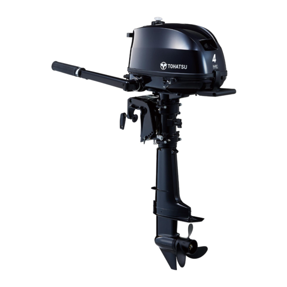
Summary of Contents for TOHATSU MFS 4D
- Page 1 O W N E R’ S M A N U A L トーハツ船外機 オーナーズマニュアル Original instructions MFS 4D MFS 5D MFS 6D OB No.003-11154-4BC1...
- Page 2 MANUAL IN A SAFE LOCATION FOR FUTURE REFERENCE. Copyright © 2023 Tohatsu Corporation. All rights reserved. No part of this manual may be reproduced or transmitted in any from or by any means without the express written permission of Tohatsu Corporation.
- Page 3 In case you encounter any problems, please contact an authorized TOHATSU service shop or dealer for assistance. Tohatsu Corporation reserves the right to change, modify, add, or remove a part or whole of the owner’s manual without prior notice and incurring any obligations.
- Page 4 BE COVERED BY THE APPLICABLE LIMITED WARRANTY, IF THIS PROCEDURE IS NOT FOL- LOWED. ENOM00003-1 PRE-DELIVERY INSPECTION Make sure Pre-delivery inspection has been properly done by authorized TOHATSU dealer before operating your outboard motor. ENOM00005-1 Serial Number Your outboard motor has a unique serial number. The serial number is identification of outboard motor and is located on the outboard motor as shown in the figures below.
- Page 5 ENOM00007-0 NOTICE: DANGER/WARNING/CAUTION/Note Before installing, operating or otherwise handling your outboard motor, be sure to thor- oughly read and understand this Owner's Manual and carefully follow all of the instruc- tions. Of particular importance is information preceded by the words “DANGER,” “WARNING,”...
-
Page 7: Table Of Contents
CONTENTS 1. GENERAL SAFETY INFORMATION ........10 2. - Page 8 12. ACCESSORIES KIT ..........71 13.
- Page 9 INDEX 1. GENERAL SAFETY INFORMATION 2. SPECIFICATIONS 3. PARTS NAME 4. LABEL LOCATIONS 5. INSTALLATION 6. PRE-OPERATING PREPARATIONS 7. ENGINE OPERATION 8. REMOVING AND CARRYING THE OUTBOARD MOTOR 9. ADJUSTMENT 10. INSPECTION AND MAINTENANCE 11. TROUBLESHOOTING 12. ACCESSORIES KIT 13. PROPELLER TABLE...
-
Page 10: General Safety Information
GENERAL SAFETY INFORMATION ENOM00009-1 SAFE OPERATION OF BOAT As the operator/driver of a boat, you are responsible for the safety of those aboard and those in other boat around yours, and for following local boating regulations. You should be thoroughly knowledgeable on how to correctly operate the boat, outboard motor, and accessories. - Page 11 Be sure to use genuine parts, genuine lubricants, or recom- mended lubricants. Be aware that the installation and use of parts not approved by Tohatsu Corporation will void warranty and may lead to unsafe operating conditions. ENOM00011-1...
-
Page 12: Specifications
SPECIFICATIONS ENOM00810-A MODEL FEATURE Model F6D SP*2 Type (D) MF (D) MF (D) MF Transom heights Tiller Handle Remote Control *1 Separate fuel tank Dual fuel tank Manual tilt *1: Option *2: SP model equip with charging coil as a standard. ENOM00811-A MODEL NAME EXAMPLE F 6 DSUL SP... - Page 13 Remark: Specifications subject to change without notice. *1: With propeller, with battery cable. *2: Equippted only for SP model, the other models OPTION. *3: Transom angle is at -12° Tohatsu outboard is power rated in accordance with ISO8665 (propeller shaft output).
- Page 14 SPECIFICATIONS Service data Model MFS5/ MFS6DS MFS4/5/6DD Item Dual Tank Separate Tank Unleaded Regular Gasoline : R+M/2: 87 or higher Fuel RON: 91 or higher Fuel Tank Capacity L (US gal) 1.2 (0.32) integral*4 12 (3.17) Separate Grade API: SH, SJ, SL SAE: 10W-30, 10W-40 Engine Oil 450 (15/16) (US/Imp.qt)
-
Page 15: Parts Name
PARTS NAME ENOM00402-A 4D, 5D, 6D ENOF01502-1 Tilt Handle Thrust Rod Fuel Cock Top Cowl Clamp Bracket Engine Oil Filler Cap Bottom Cowl Clamp Screw Spark Plug Cooling Water Check Port Throttle Grip Engine Oil Drain Screw Tilt Lever Shift Lever Steering Adjustment Screw Starter Handle Anode... - Page 16 PARTS NAME ENOM00822-0 Remote control box & Fuel tank ENOF01404-2 Control Lever Air vent screw Neutral lock arm Fuel tank cap PTT switch Fuel connector (Engine side) Free throttle lever Primer bulb Main switch Fuel connector (Fuel tank Stop switch side) Stop switch lock Stop switch lanyard...
-
Page 17: Label Locations
LABEL LOCATIONS ENOM00019-A Warning label locations 2, 3 ENOF01503-4... - Page 18 LABEL LOCATIONS Read owner's manual. 5-4. ELECTRICAL SHOCK HAZARD High voltage can cause severe elec- trical shock. Do not touch electrical components such as ignition coil or spark plug ENOF00120-0 cord when star ting or while the Oil pressure lamp (See page 31). engine is in operation.
- Page 19 LABEL LOCATIONS Warning regarding gasoline (See page 26). ENOF00005-S Warning regarding gasoline (See page 26). ENOF00005-L...
- Page 20 LABEL LOCATIONS ENOM00019-B CE label locations 1521 CAN ICES-2 / NMB-2 ENOF01504-3 1. Model code (Model name) 2. Serial No. 3. Rated power 4. Dry mass weight( Without propeller, with battery cable) 5. Manufacturer name 6. Manufacturer address 7. Authorised representative 8.
-
Page 21: Installation
INSTALLATION ENOM00024-B Keep the outboard motor in a vertical 1. Mounting the outboard position when mounting. motor on boat ENOW00006-1 WARNING Most boats are rated and certified for their maximum allowable horsepower, as shown on the boat’s certification plate. Do not equip your boat with an outboard motor that exceeds this limit. - Page 22 INSTALLATION ENOM00831-0 Mounting the outboard motor 1. Set the outboard motor to appropri- ate position. 2. Tighten the clamp screws by turning 5−25 mm their handles. (0.2−1 in) 3. Secure the outboard motor to the boat with a rope to prevent acciden- ENOF01506-0 tal loss of the outboard motor over- 1.
-
Page 23: Battery Installation (For Sp Model)
INSTALLATION ENOM00029-A ENOW00014-0 2. Battery installation (For SP CAUTION model) Make sure that the battery leads do not get stuck between the outboard motor ENOW00012-1 and boat when turning, etc. WARNING The starter motor may fail to operate if the leads are incorrectly connected. Battery electrolyte contains sulfuric acid Be sure to correctly connect the (+) and and is hazardous, causes a burn if come in... - Page 24 INSTALLATION 2. Place the battery box in a convenient position and away from possible water spray. Securely fasten both the box and the battery so they do not shake loose. 3. Connect the positive lead (+) to the positive terminal (+) of the battery, and then connect the negative lead (—).
-
Page 25: Pre-Operating Preparations
When operating an outboard motor with The fuel system components on your gasoline containing ethanol, storing gasoline TOHATSU outboard motor will withstand in the fuel tank for long periods should be up to 10% ethyl alcohol (hereinafter avoided. Storing gasoline for long periods referred to as the "ethanol") content in... -
Page 26: Fuel Filling
PRE-OPERATING PREPARATIONS ENOW00018-1 Stop the engine, and do not start the engine during refueling. WARNING Do not smoke. Be careful not to overfill fuel tank. Wipe Fuel leakage can cause fire or explosion, up any spilled gasoline immediately. potentially leading to severe injury or loss of life. - Page 27 PRE-OPERATING PREPARATIONS When using integral tank When using separate tank 1. Before opening fuel tank cap, turn air Fully open the air vent screw on the tank cap and release internal pres- vent screw two turns counterclock- sure. wise to release air pressure in the fuel tank.
-
Page 28: Engine Oil Filling
PRE-OPERATING PREPARATIONS ENOM00037-C 3. Engine oil filling ENOW00022-2 CAUTION The engine oil is drained for shipping at the factory. Be sure to fill the engine oil to the proper level before starting the engine. ENOF00446-1 ENOW00092-1 1. Oil filler cap (Dipstick) CAUTION Do not overfill engine oil, or engine oil could leak and/or engine could be dam-... - Page 29 PRE-OPERATING PREPARATIONS Engine oil volume Approximately 450 mL (0.48 US qt.) ENOW0002A-A CAUTION Use of engine oils that do not meet these requirements will result in reduced engine life, and other engine problems.
-
Page 30: Break-In
PRE-OPERATING PREPARATIONS ENOM00033-A 4. Break-In Your new outboard motor and lower unit ENOW00023-1 require break-in for the moving compo- CAUTION nents a ccording to the conditions Operating the outboard motor without described in the following timetable. break-in can shorten life. Please refer to ENGINE OPERATION sec- If any abnormality is experienced during the tion (See page 33) to learn how to cor-... -
Page 31: Warning System
PRE-OPERATING PREPARATIONS ENOM00039-A 5. Warning system If outboard motor encounters an abnor- mal condition of fault, warning lamp (LED) will be on (engine will not be stopped). See next page for conditions which will lead to an abnormal condition or fault. ENOM00040-D Location of warning lamp Warning lamp (LED) - Page 32 PRE-OPERATING PREPARATIONS ENOM00041-D Warning indicators, faults and remedy Warning indicators Description of faults Remedy Sound Lamp (LED) On for several Normal system test when start up sec.l Engine speed exceeds maximum allowable RPM Low oil pressure Remarks *1: In this case, oil pressure switch is “ON”. High speed ESG (Electronic Safety Governor) High speed ESG is a device to prevent over revolution of the engine.
-
Page 33: Engine Operation
ENGINE OPERATION ENOM00042-0 ENOM00044-C Before starting 1. Fuel feeding ENOM00246-0 ENOW00029-1 Oil Level checking WARNING Check the engine oil level before each use. If the oil level is low or too high, the When opening fuel tank cap, be sure to fol- low the procedure described below. -
Page 34: Starting The Engine
ENGINE OPERATION ENOW00404-0 5. Squeeze primer bulb until it becomes stiff to feed fuel to carburetor. Point CAUTION the arrow mark upward when priming. When using integral tank, disconnect fuel connector. ENOW00947-0 CAUTION When using a separate tank, be sure that the fuel line is not kinked and is connected securely. - Page 35 ENGINE OPERATION 1. Water level is at least 10 cm (4 in.) above the anti-ventilation plate to avoid over- Tiller handle type heating of the engine. 1. Be sure to install the stop switch lock 2. Run at idling only to the stop switch, and attach the 3.
- Page 36 ENGINE OPERATION ENON00501-0 7. Check the cooling water from cooling Note water check port. Choke is not necessary when the engine is warm. Set the throttle grip to “RE-START” position. ENON00502-0 Note If engine does not start with 4 or 5 times starting operation, push the knob back and restart.
- Page 37 ENGINE OPERATION ENOF00435-0 ENOF01521-1 5. Tie a loop in the another end of the 1. Cowl latch emergency starter rope and attach 2. Disconnect the rink of the starter socket wrench, Both the loop and the lock rod. wrench are provided in outboard motor box.
-
Page 38: Warming Up The Engine
ENGINE OPERATION 9. Once the outboard motor is started, ENOM00046-A do not reinstall the recoil starter and 4. Forward, reverse, and top cowl. acceleration ENOM00043-A 3. Warming up the engine ENOW00037-1 WARNING ENOW00932-1 Before shifting into forward or reverse, make CAUTION sure that boat is properly moored and out- board motor can be steered fully to the right... - Page 39 ENGINE OPERATION ENOW00861-1 ENOW00864-0 WARNING CAUTION Do not shift at high boat speed, or control Do not increase engine speed unnecessarily may be lost, fall down or causing passen- when the shift is in neutral and reverse, or ger(s) to be thrown overboard. Leading to engine damage may occur.
-
Page 40: Stopping The Engine
ENGINE OPERATION Acceleration 3. Push the stop switch. Open throttle grip gradually. ENOF01119-0 ENOF00439-B1 ENOF00210-0 1. Throttle grip ENOM00049-A ENOW00869-1 5. Stopping the engine WARNING ENOW00868-1 After stopping the engine: WARNING Close the air vent screw on the fuel tank cap. -
Page 41: Steering
ENGINE OPERATION ENOM00910-1 Spare emergency stop switch lock (For CE marking model) A spare emergency stop switch lock is provided in the accessories bag. Make sure that spare stop switch lock is available before operating outboard motor. When used as described, the emergency stop switch clip and emergency stop switch lanyard system stops the engine if the operator is thrown overboard. - Page 42 ENGINE OPERATION The trim angle of the outboard motor can be adjusted to suit the transom angle of the hull, and load conditions. Choose an appropriate trim angle that will allow the anti-ventilation plate to run parallel to the water surface during operation. ENOF00053-0 ENOM00052-0 Proper trim angle...
-
Page 43: Tilt Up And Down
ENGINE OPERATION 5. Reinstall the thrust rod in the desired ENON00921-1 Note position securely. After use, leave the outboard motor 6. Gentry tilt down the outboard motor. upright for a minute to drain the water from inside the engine. ENOM00060-A ENOM00423-0 8. -
Page 44: Shallow Water Operation
ENGINE OPERATION ENOM00424-0 ENOW00054-1A Tilt down CAUTION Slightly tilt the motor up, and pull the tilt lever toward you to release the tilt-lock. Do not over tilt the outboard motor when driving in shallow water, or air may be sucked Then lower the motor slowly. -
Page 45: Removing And Carrying The Outboard Motor
REMOVING AND CARRYING THE OUTBOARD MOTOR ENOM00070-K 1. Removing the outboard motor ENOW00064-1 CAUTION Engine may be hot immediately after opera- tion and could cause burns if came in con- tact. Allow engine to cool down before attempting to carry the outboard. ENOF01505-1 ENOM00071-A 2. -
Page 46: Trailering
REMOVING AND CARRYING THE OUTBOARD MOTOR ENOF01510-1 Keep the outboard motor in a vertical position when carrying. ENOF01532-0 The optional outboard motor stand is recommended for keeping the outboard motor vertical both during transport and storage. ENOF01533-0 ENON00941-0 Note When laying the outboard front-side down, turn the clamp bracket 90°... - Page 47 REMOVING AND CARRYING THE OUTBOARD MOTOR Fuel leakage is a fire or explosion hazard, which can cause serious injury or death. Tiller handle type While transpor ting outboard motor attached to the boat on a trailer, properly tighten the steering friction bolt to pre- vent the outboard motor from moving (page 48).
-
Page 48: Adjustment
ADJUSTMENT ENOM00073-0 EENOM00074-A 1. Steering friction 2. Throttle grip friction Tiller handle type ENOW00074-1B WARNING ENOW00074-1E WARNING Do not overtighten the throttle adjustment screw or it could result in difficult handling Do not over tighten the steering friction of the outboard motor, resulting in the loss adjustment screw or it could result in diffi- of control causing an accident and could cult handling of the outboard motor, result-... -
Page 49: Inspection And Maintenance
INSPECTION AND MAINTENANCE ENOM00077-1 Care of your outboard motor To keep your outboard motor in the best operating condition, it is very important that you perform daily and periodic maintenance as suggested in the mainte- nance schedules as follows. ENOW00077-1 CAUTION Your personal safety and that of your pas- sengers depends on how well you main-... -
Page 50: Daily Inspection
INSPECTION AND MAINTENANCE ENOM00428-0 1. Daily Inspection Perform the following checks before and ENOW00078-1 after use. WARNING Do not use outboard motor if any abnormal- ity is found during pre-operation check oth- erwise it could result in severe damage to the motor or severe personal injury. - Page 51 INSPECTION AND MAINTENANCE ENOM00081-B ENON00025-0 Oil level checking Note 1. Place the engine in a vertical position. Consult with an authorized dealer if the 2. Remove the top cowl and the oil filler engine oil is milky color, or appears con- taminated.
- Page 52 INSPECTION AND MAINTENANCE ENOM00083-B 3. Connect a water hose. Turn on the Washing outboard motor water and adjust the flow. ENOW00920-0 Continue flushing the outboard motor CAUTION for 3 to 5 minutes. 4. After the flushing, be sure to reattach When washing the outboard motor, be care- the water plug.
- Page 53 CAUTION If the fuse continues to blow, request an When starting the outboard motor in the authorized Tohatsu dealer to inspect the test tank, make sure that: outboard motor. 1. Water level is at least 10 cm (4 in.) above 1.
-
Page 54: Periodic Inspection
INSPECTION AND MAINTENANCE ENOM00431-1 2. Periodic Inspection It is important to inspect and maintain your outboard motor regularly. Make sure to per- form each service at interval specified in the chart below. Maintenance intervals are determined by the number of hours outboard motor has been used or number of months, whichever comes first. - Page 55 Frequent sudden acceleration and sudden deceleration Frequent stop start operation Frequent shifting operation Frequent operation in acidic, polluted, muddy, sandy, or shallow water Appropriate maintenance can prolong your engine life. Consult your Tohatsu authorized dealer for suitable maintenance interval depending on operating and environmental conditions.
- Page 56 INSPECTION AND MAINTENANCE ENOM00091-B 3. Put an oil drain pan under the oil drain Engine oil replacement bolt. ENOW00091-1 4. Remove the oil drain bolt and com- CAUTION pletely drain oil from the engine. You may be injured due to high engine tem- peratures if you fill engine oil just after oper- ation.
- Page 57 INSPECTION AND MAINTENANCE ENON00031-0 Note If any amount of water is found in engine oil, making it milky white, consult dealer. If engine oil is contaminated with fuel, emitting strong fuel smell, consult dealer. Some oil dilution is normal if engine is idled or trolled for long periods, espe- ENOF00446-1 cially in cooler water temperatures.
- Page 58 INSPECTION AND MAINTENANCE ENOM00094-0 Fuel filter (for engine) 1. Replace the fuel filter provided inside of engine cover if there is water or dirt inside. ENOF00455-1 1. Carburetor 2. Fuel filter 3. Fuel pump ENOF01226-1 4. Fuel pipe 1. Fuel pick-up 2.
- Page 59 INSPECTION AND MAINTENANCE 2. Remove the oil plugs (lower and 4. Install the upper oil plug, and then upper), and completely drain the gear remove oil tube nozzle and install the oil into a pan. lower oil plug. Oil plug specified tightening torque 4Nm (3 ft lb, 0.4 kgf ENOW00095-0...
- Page 60 INSPECTION AND MAINTENANCE and starter key attached, or engine could 5. Install the thrust holder, propeller, accidentally start leading to serious per- stopper, washer and propeller nut sonal injury. Disconnecting battery cable onto the shaft. is recommended (if equiped). The propeller edge is thin and sharp. Wear the gloves while installing or removing to protect your hands.
- Page 61 INSPECTION AND MAINTENANCE ENOM00087-A Use spark plug NGK DCPR-6E. Spark plugs replacement ENOW00087-1 WARNING Do not reuse spark plug, if the insulation is damaged or sparks can leak through crack, potentially leading to electric ENOF00085-0 shock, explosion and/or fire. Do not touch spark plug(s) immediately 1.
- Page 62 INSPECTION AND MAINTENANCE ENOM00088-1A Anode replacement A sacrificial anode protects the outboard motor from galvanic corrosion. Anode is located on the gear case, cylinder etc.. When the anode is eroded more than 1/3 of original size, replace it. ENON00029-1 Notes Never grease or paint the anode.
- Page 63 INSPECTION AND MAINTENANCE ENOM00960-0 Grease point Apply waterproof grease to the parts shown below. ENOF01519-1...
-
Page 64: Off-Season Storage
INSPECTION AND MAINTENANCE 4. Remove the spark plug and put a tea- ENOM00100-A 3. Off-season storage spoon of engine oil or spray storage oil into the combustion chamber ENOW00934-0 through the spark plug holes. WARNING 5. Pull the recoil starter several turns to lubricate inside the cylinder. - Page 65 INSPECTION AND MAINTENANCE Otherwise, engine's exterior may be dam- ENON00941-0 Note age d or wa ter may enter th e cylinder through the exhaust port and cause engine When laying the outboard front-side problems. down, turn the clamp bracket 90° clock- wise or anti-clockwise so that it does not interfere with the ground.
- Page 66 INSPECTION AND MAINTENANCE Keep the fuel tank well away from sources of ignition, e.g. sparks or open flames Perform all work outdoors or in a well ventilated place. ENOW00097-0 WARNING Be sure to use cloth to remove fuel remain- ing in the cowl and dispose of it in accor- d an c e w i t h l o c a l f ir e pr e ve n t i o n an d environment protection regulations.
-
Page 67: Pre-Season Check
INSPECTION AND MAINTENANCE ENOM00104-A 9. Run the engine for 10 minutes at half 4. Pre-season check throttle. The oil used for storage inside the engine will be circulated The following steps must be taken when out to assure optimum performance. first using the engine after off-season storage. -
Page 68: Cold Weather Precautions
INSPECTION AND MAINTENANCE ENOM00106-1 ENOM00120-2 6. Cold weather precautions 8. Auxiliary outboard motor operation If you moor your boat in cold weather at temperatures below 0°C (32°F), water When the auxiliary outboard motor is not residue in water pump may freeze and in operation, be sure to remove the stop may damage the pump, impeller, etc. -
Page 69: Troubleshooting
TROUBLESHOOTING ENOM00109-0 If you encounter a problem, check the list below to determine the cause and to take the proper action. An authorized dealer will always be happy to provide any assistance and information. Possible cause Empty fuel tank Incorrect connection of fuel system Air entering fuel line Deformed or damaged fuel hose Closed air vent on fuel tank... - Page 70 TROUBLESHOOTING Possible cause Incorrect adjustment of throttle link Insufficient cooling water flow, clogged or defective pump Faulty thermostat Cavitation or ventilation Incorrect propeller selection Damaged or bent propeller Improper thrust rod position Unbalanced load on boat Transom too high or too low...
- Page 71 ACCESSORIES KIT ENOM00562-1 The followings are a list of the tools and spare parts provided with the motor. Items Quantity Remark Tool bag Pliers Socket wrench 10 × 13 mm Service tools Socket wrench 16 mm Socket wrench handle Screwdrivers Cross-and straight-point Screwdriver handle Emergency starter rope...
- Page 72 PROPELLER TABLE ENOM00438-0 Use a genuine propeller. A propeller must be selected so that the engine RPM measured at wide open throttle while cruising is within the recommended range. 4: 4500–5500 min (rpm) 5: 4500–5500 min (rpm) 6: 5000–6000 min (rpm) Propeller Size (Diameter ×...
- Page 73 INSPECTION & MAINTENANCE LOG Date Engine Hour Inspection/Maintenance Performed Performed by...
- Page 74 O W N E R’ S M A N U A L MFS 4D MFS 5D MFS 6D 5-4, Azusawa 3-Chome, Itabashi-Ku Tokyo 174-0051, Japan Tel: +81-3-3966-3117 Fax: +81-3-3966-2951 www.tohatsu.com...
Need help?
Do you have a question about the MFS 4D and is the answer not in the manual?
Questions and answers