Table of Contents
Advertisement
Quick Links
Advertisement
Table of Contents

Related Manuals for Vaisala BAROCAP PTB330


Summary of Contents for Vaisala BAROCAP PTB330
- Page 1 USER'S GUIDE Vaisala BAROCAP® Digital Barometer PTB330 M210855EN-D...
- Page 2 English versions are applicable, not the translations. The contents of this manual are subject to change without prior notice. This manual does not create any legally binding obligations for Vaisala towards customers or end users. All legally binding obligations and agreements are included exclusively in the applicable supply contract or the General Conditions of Sale and General Conditions of Service of Vaisala.
-
Page 3: Table Of Contents
Alternate Wiring Systems............27 Signal and Power Supply Wiring......... 28 M-12 (8-Pin) Connector............30 D-9 Connector..............31 Optional Modules ..............32 AC Power Supply Module ........... 32 Installation ..............33 Warnings ................34 VAISALA ________________________________________________________________________ 1... - Page 4 USER'S GUIDE____________________________________________________________________ Galvanic Isolation for Output ..........37 Analog Output Module AOUT-1T ........38 Installation and Wiring ............38 Relay Module RELAY-1L ............40 Installation and Wiring ............40 Selecting the Activation State of the Relay ......41 RS-422/RS-485 Interface Module (RS485-1) .....42 ...
- Page 5 SMODE POLL.............. 100 SCOM ................100 OPEN ................101 CLOSE ................. 101 SEND ................101 Operating Analog Output ............ 102 Changing Output Mode and Range ........102 Analog Output Quantities ..........104 VAISALA ________________________________________________________________________ 3...
- Page 6 USER'S GUIDE____________________________________________________________________ AMODE/ASEL ..............104 Analog Output Tests............105 ATEST ................105 Analog Output Fault Indication Setting......105 AERR................105 CHAPTER 5 MAINTENANCE..................107 Periodic Maintenance............107 Cleaning ................107 Error States ................107 Technical Support ..............110 Product Returns..............110 ...
- Page 7 ICAOQNH Mode for QNH and QFE......134 APPENDIX B UNIT CONVERSION TABLES..............135 APPENDIX C PA11A EMULATION MODE ..............139 Activating the PA11A Emulation Mode ......139 PA11A Message Format ............140 VAISALA ________________________________________________________________________ 5...
- Page 8 USER'S GUIDE____________________________________________________________________ List of Figures Figure 1 Barometer Body................15 Figure 2 Open Barometer Interior............16 Figure 3 Standard Mounting ..............17 Figure 4 Mounting with Wall Mounting Kit ..........18 Figure 5 Dimensions of Plastic Mounting Plate ........18 ...
- Page 9 Table 37 Unit Conversion Table for Settings HHCP and HQFE ... 137 Table 38 Unit Conversion Table for Settings HQNH......137 Table 39 Unit Conversion Table for Setting TQFE........ 137 VAISALA ________________________________________________________________________ 7...
- Page 10 USER'S GUIDE____________________________________________________________________ This page intentionally left blank. 8 ___________________________________________________________________ M210855EN-D...
-
Page 11: Chapter 1 General Information
This chapter provides general notes for the manual and the product. About This Manual This manual provides information for installing, operating, and ® maintaining Vaisala BAROCAP Digital Barometer PTB330. Contents of This Manual This manual consists of the following chapters: - Chapter 1, General Information, provides general notes for the manual and the product. -
Page 12: Version Information
USER'S GUIDE____________________________________________________________________ - Appendix B, Unit conversion tables, contains the unit conversion tables. - Appendix C, PA11A Emulation Mode, describes the PA11A emulation mode of the PTB330 series. Version Information Table 1 Manual Revisions Manual Code Description M210855EN-D December 2012. This version. Command descriptions rewritten. -
Page 13: Safety
ESD Protection Electrostatic Discharge (ESD) can cause immediate or latent damage to electronic circuits. Vaisala products are adequately protected against ESD for their intended use. However, it is possible to damage the product by delivering electrostatic discharges when touching, removing, or inserting any objects inside the equipment housing. -
Page 14: Recycling
Microsoft Corporation. License Agreement All rights to any software are held by Vaisala or third parties. The customer is allowed to use the software only to the extent that is provided by the applicable supply contract or Software License Agreement. -
Page 15: Chapter 2 Product Overview
Table 2 on page 15. The PTB330 barometer is available with one, two, or three barometer modules. The barometer can be used successfully both in accurate pressure measurement applications at room temperature and in demanding automatic weather station applications. VAISALA _______________________________________________________________________ 13... -
Page 16: Basic Features And Options
- Optional USB cable for service use or data transfer Pressure Measurement ® The PTB330 series barometers use a BAROCAP silicon capacitive absolute pressure sensor developed by Vaisala for barometric pressure ® measurement applications. The BAROCAP sensor has excellent hysteresis and repeatability characteristics, low temperature ®... -
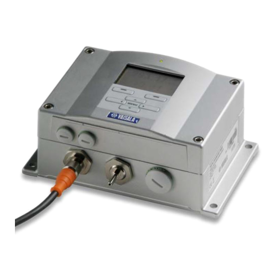
Page 17: Outer Structure Of The Barometer
Numbers refer to Figure 1 above: Cable for signal/powering Ø 8 ... 11 mm Pressure port Cable for optional power supply/relay module Ø 8 ... 11 mm Cover LED Display with keypad (optional) Cover screw (4 pcs) VAISALA _______________________________________________________________________ 15... -
Page 18: Inner Structure Of The Barometer
USER'S GUIDE____________________________________________________________________ Inner Structure of the Barometer Figure 2 Open Barometer Interior Numbers refer to Figure 2 above: Adjustment button with indicator LED Galvanic isolation module (optional) Power supply mode selections (Do not change the factory settings!) Service port (RS-232) Module 1/Module 3 connectors User port Module 2/Module 4 connectors... -
Page 19: Chapter 3 Installation
The housing can be mounted either without the mounting plate or with optional mounting plates. Standard Mounting without Mounting Plate Mount the housing by fastening the barometer to the wall with 4 screws, for example M6 (not provided). Figure 3 Standard Mounting VAISALA _______________________________________________________________________ 17... -
Page 20: Wall Mounting With Wall Mounting Kit
USER'S GUIDE____________________________________________________________________ Wall Mounting with Wall Mounting When mounting with wall mounting kit the mounting plate (Vaisala order code 214829) can be installed directly on wall or onto a standard wall box (also US junction box). When wiring through back wall, remove the plastic plug from the wiring hole in the barometer before mounting. -
Page 21: Mounting With Din Rail Installation Kit
Mounting with DIN Rail Installation DIN rail installation kit includes a wall mounting kit, 2 clip-fasteners, and 2 screws M4 x 10 DIN 7985 (Vaisala order code 215094). To mount PTB330 using the DIN rail installation kit: Attach two spring holders to the plastic mounting plate by using the screws provided in the installation kit. -
Page 22: Figure 7 Vertical Pole (Side)
USER'S GUIDE____________________________________________________________________ Figure 7 Vertical Pole (Side) Figure 8 Vertical Pole (Front) Numbers refer to Figure 8 above: Fixing brackets (2 pcs) M8 (provided) for 30 ... 102 mm poles. Mounting nuts M8 (4 pcs) Figure 9 Horizontal Pole Number refers to Figure 9 above: Mounting nuts M8 (4 pcs) 20 __________________________________________________________________ M210855EN-D... -
Page 23: Figure 10 Mounting With Metal Wall Mounting Plate
Mount the plate to wall with 4 screws M8 (not provided) Fasten the barometer to the mounting plate with 4 fixing screws M6 (provided) Note the position of the arrow when mounting. This side must be up when mounting. Figure 11 Dimensions of Metal Mounting Plate (mm) VAISALA _______________________________________________________________________ 21... -
Page 24: Mounting Rain Shield With Installation Kit
Figure 12 Mounting Rain Shield with Installation Kit Numbers refer to Figure 12 above: 1 = Fasten the rain shield with installation kit (Vaisala order code: 215109) to the metal mounting plate with 2 (M6) mounting screws (provided). 2 = Fasten the mounting plate with rain shield with installation kit to the wall or to the pole (see pole installation). -
Page 25: Figure 13 Panel Mounting Frame
Chapter 3 _______________________________________________________________ Installation Figure 13 Panel Mounting Frame Numbers refer to Figure 13 above: 1 = Panel (not included) 2 = Panel mounting frame Figure 14 Panel Mounting Dimensions VAISALA _______________________________________________________________________ 23... -
Page 26: Pressure Connections
USER'S GUIDE____________________________________________________________________ Pressure connections The barometer is equipped with a barbed pressure fitting which is ideal for 3-4mm internal diameter tubing. If you require some other pressure fitting, you can replace the standard barbed fitting. The main pressure connector in the barometer housing has a metric M5 internal thread. -
Page 27: General About Wiring And Grounding
Cable for optional power supply/relay module Ø 8 ... 11 mm When there is high electric noise level (for example, near powerful NOTE electric motor) in the operating environment, Vaisala recommends using shielded cables or taking care that the signal cables are separated from other cables. -
Page 28: Grounding The Cables
USER'S GUIDE____________________________________________________________________ Grounding the Cables To ensure the best possible EMC performance, you must ground the screen of the electrical cable as shown in 1212-005 Figure 16 below and in the instructions below that. 1212-005 Figure 16 Grounding the Screen of Electrical Cable To ground the electrical cables: Cut back outer sheath to desired length. -
Page 29: Grounding The Barometer Housing
- When using basic wiring, see section Signal and Power Supply Wiring on page 28. - When using 8-pin connector, see section M-12 (8-Pin) Connector on page 30. - When using D-9 connector, see section D-9 Connector on page 31. - When using an optional external AC-adapter. VAISALA _______________________________________________________________________ 27... -
Page 30: Signal And Power Supply Wiring
USER'S GUIDE____________________________________________________________________ Signal and Power Supply Wiring When wiring the power supply module, see section AC Power Supply Module on page 32. Figure 17 Screw Terminal Block on Motherboard Numbers refer to Figure 17 above: = Power control (0VDC = OFF, 5VDC = ON, if feature enabled) = User port (RS-232 terminals) = Power supply terminals 10 ... - Page 31 Close the cover and replace the cover screws. The barometer is ready for use. NOTE If you have chosen the external power control option, you must remove the wire between the "Power control" and "Power +" - terminals prior to using the power control feature. VAISALA _______________________________________________________________________ 29...
-
Page 32: M-12 (8-Pin) Connector
USER'S GUIDE____________________________________________________________________ M-12 (8-Pin) Connector NOTE The 8-pin connector cannot be used with relay modules or power supply modules that have AC (mains) power connection. Figure 18 Wiring of Optional M-12 (8-Pin) Connector Table 3 Pin Assignments to RS-232-/485 Serial Output Pin/Terminal Wire Serial Signal... -
Page 33: D-9 Connector
Supply voltage (10...30 VDC) (10...30 VDC) (10...30 VDC) NOTE The D-9 connector cannot be used with relay modules or power supply modules that have AC (mains) power connection. NOTE The D-9 connector is not IP65 protection classified. VAISALA _______________________________________________________________________ 31... -
Page 34: Optional Modules
USER'S GUIDE____________________________________________________________________ Optional Modules AC Power Supply Module The AC (mains) power connection may be connected to the power supply module only by an authorized electrician, unless you order a unit with a pre-installed power cord. A readily accessible disconnect device must be incorporated in the fixed wiring. -
Page 35: Installation
Do not detach the power supply module from the barometer when the WARNING power is on. WARNING Do not connect the mains power to power supply module when it is not installed in the barometer. Always connect protective ground terminal. WARNING VAISALA _______________________________________________________________________ 33... -
Page 36: Warnings
USER'S GUIDE____________________________________________________________________ Warnings 34 __________________________________________________________________ M210855EN-D... - Page 37 Chapter 3 _______________________________________________________________ Installation VAISALA _______________________________________________________________________ 35...
- Page 38 USER'S GUIDE____________________________________________________________________ 36 __________________________________________________________________ M210855EN-D...
-
Page 39: Galvanic Isolation For Output
This module prevents harmful grounding loops. NOTE Output isolation module is not needed when using the AC power supply module. Figure 21 Galvanic Power Isolation Number refers to Figure 21 above: Power Supply module VAISALA _______________________________________________________________________ 37... -
Page 40: Analog Output Module Aout-1T
USER'S GUIDE____________________________________________________________________ Analog Output Module AOUT-1T Figure 22 Analog Output 1 Module AOUT-1T Numbers refer to Figure 22 above: Flat cable pins Screw terminals for signal line DIP switches to select the output mode and range Installation and Wiring To install analog output module AOUT-1T: Disconnect the power. -
Page 41: Figure 23 Analog Output Dip Switch Positions
For instructions on how to operate the analog output, see section NOTE Operating Analog Output on page 102. NOTE Only one of the switches 1 and 2 can be ON at a time. Only one of the switches 3...7 can be ON at a time. VAISALA _______________________________________________________________________ 39... -
Page 42: Relay Module Relay-1L
USER'S GUIDE____________________________________________________________________ Relay Module RELAY-1L The barometer can be equipped with one configurable relay module. The module contains two configurable relays. NOTE The relay module is only intended for DC use. Installation and Wiring To install relay module RELAY-1L: Disconnect the power and open the barometer cover. If the relay-module is installed in the factory, continue with step 5. -
Page 43: Selecting The Activation State Of The Relay
Operating Relays on page 93. Figure 24 Relay Module Numbers refer to Figure 24 above: Indication led for the relay 1 Relay test buttons Flat cable pins Indication led for relay 2 VAISALA _______________________________________________________________________ 41... -
Page 44: Rs-422/Rs-485 Interface Module (Rs485-1)
USER'S GUIDE____________________________________________________________________ WARNING The relay module may contain dangerous voltages even if the barometer power has been disconnected. Before opening the barometer you must switch off both the barometer and the voltage connected to the relay terminals. WARNING Do not connect the mains power to the relay unit. RS-422/RS-485 Interface Module (RS485-1) 1102-023... -
Page 45: Installation And Wiring
If you are adding a new module, continue to the next step. Connect to the service port, and execute the MODS command to register the changes. Switch the power off and back on again to clear related errors and to activate the changes. VAISALA _______________________________________________________________________ 43... -
Page 46: Figure 26 4-Wire Rs-485 Bus
USER'S GUIDE____________________________________________________________________ If you use the internal termination of the barometer at the end of the NOTE RS-485 bus (instead of using separate terminators) removing that barometer may block the bus operation. Table 5 Connecting the Twisted Pair Wires to the Screw Terminals Screw terminal Data line (2-wire RS-485) -
Page 47: Figure 27 2-Wire Rs-485 Bus
Switch Term off Term off Common 2/4 wire off RS422 off 120R Stub RS485-1 Termination Junction box 1102-027 Figure 27 2-Wire RS-485 Bus Table 7 2-Wire (Switch 3: Off) RS-485 master Data PTB330 <-> <-> Common Common VAISALA _______________________________________________________________________ 45... - Page 48 USER'S GUIDE____________________________________________________________________ This page intentionally left blank. 46 __________________________________________________________________ M210855EN-D...
-
Page 49: Chapter 4 Operation
Display shows you the measurement values of the selected quantities in the selected units. You can select 1... 4 quantities for the basic display. The basic display shows two quantities (P and P ) by default. Figure 28 Basic Display VAISALA _______________________________________________________________________ 47... -
Page 50: Menus And Navigation
USER'S GUIDE____________________________________________________________________ Numbers refer to Figure 28 on page 47: The Info shortcut key/left function button with guiding text The Graph shortcut button/right function button with guiding text Quantities selected for display. Note that units displayed (for example P) depend on the type of measurements. NOTE To return directly to the basic display from any view, press and hold down the top right button on the front panel for two seconds. -
Page 51: Pressure 3H Trend And Tendency Reading
Trend (middlemost numeric value in the example), that is, pressure change during last 3 hours Pressure Tendency Graphics and Codes The characteristic symbols of pressure tendency during the 3 hours preceding the time of observation are described in Figure 31 on page VAISALA _______________________________________________________________________ 49... -
Page 52: Figure 31 Pressure Tendency Description
USER'S GUIDE____________________________________________________________________ Figure 31 Pressure Tendency Description where: Increasing, then decreasing; atmospheric pressure the same or higher than three hours ago Increasing, then steady; or increasing, then increasing more slowly; atmospheric pressure now higher than three hours ago Increasing (steadily or unsteadily); atmospheric pressure now higher than three hours ago Decreasing or steady, then increasing;... -
Page 53: Using Serial Line
Trend graph: Displays a curve of average values. Each value is a calculated average over a period. Max/min graph: Displays the minimum and maximum values in a form of curve. Each value is max/min over a time period. See Table 8 on page 52. VAISALA _______________________________________________________________________ 51... -
Page 54: Table 8 Periods For Trend And Max/Min Calculations
USER'S GUIDE____________________________________________________________________ Table 8 Periods for Trend and Max/Min Calculations Observation Period for Trend/Max/Min Calculations Period (Resolution) 20 minutes 10 seconds 3 hours 90 seconds 1 day 12 minutes 10 days 2 hours 2 months 12 hours 1 year 3 days - Press the up/down arrow buttons to zoom in and out the time in the graph window. -
Page 55: Information Display
Proceed through the information views by pressing the MORE button as many times as you need to get the desired information. You can browse through the information displays also with the arrow buttons. Press the OK button to return to the basic display. VAISALA _______________________________________________________________________ 53... -
Page 56: Display Settings
USER'S GUIDE____________________________________________________________________ Display Settings Changing Quantities Open the MAIN MENU by pressing any of the arrow buttons. Select Display and press the right arrow button. Select Quantities and press the right arrow button. Select a quantity by using the up/down arrow buttons. Confirm your choice by pressing the SELECT button. -
Page 57: Rounding
To use keypad lock: To lock the keypad, press and hold down the left function button for 4 seconds (at any display). To unlock the keypad, press and hold down the OPEN button for 4 seconds. VAISALA _______________________________________________________________________ 55... -
Page 58: Measuring Settings
USER'S GUIDE____________________________________________________________________ Measuring Settings See the calculation formulas for pressure values in Appendix A, Calculation Formulas, on page 133. To change the measuring settings: Open the MAIN MENU by pressing any of the arrow buttons. Select Measuring and press the right arrow button. Select Measuring settings. -
Page 59: Serial Interface Settings
Use the arrow buttons to select ECHO. Press ON to turn to it on. Press OFF to turn it off. Press EXIT to return to the basic display. The new user port settings set using the display/keypad are effective immediately. VAISALA _______________________________________________________________________ 57... -
Page 60: System Settings
USER'S GUIDE____________________________________________________________________ System Settings Language Open the MAIN MENU by pressing any of the arrow buttons. Select System, press the right arrow button. Select Language (marked with a flag symbol), press the SELECT button. Select the menu language with up/down arrow buttons and press the SELECT button. -
Page 61: Factory Settings
Press the YES button to confirm the selection. CAUTION This function clears all the data history from the memory, all graphs included. For more information on how to handle recorded measurement data, see section Data Recording on page 90. VAISALA _______________________________________________________________________ 59... -
Page 62: Relay Settings
USER'S GUIDE____________________________________________________________________ Relay Settings Relay Outputs Figure 35 Relay Indicators on Display The number refers to Figure 35 above: List enabled relays. Activation state is shown in black. Disabled relays are not shown. Use the display/keypad to set the relay outputs: Press any of the arrow buttons to open the MAIN MENU. -
Page 63: Testing The Operation Of Relays
Press OK to go back to normal operation. Select Test relay 2 to test the output of relay 2. Press ON/OFF to activate/deactivate the output. Press OK to go back to normal operation. Press EXIT to return to the basic display. VAISALA _______________________________________________________________________ 61... -
Page 64: Analog Output Settings
USER'S GUIDE____________________________________________________________________ Analog Output Settings Analog Output Quantities Use the display/keypad to change and scale the analog output quantities: Press any of the arrow buttons to open the MAIN MENU. Select Interfaces and press the right arrow button. Select Analog outputs and press the right arrow button. Select Output 1 and press the right arrow button. -
Page 65: Analog Output Fault Indication
The MI70 link program also allows you to monitor barometer readings directly with a PC (real-time window function). The MI70 Link Interface Software is available from Vaisala. To start using the MI70 Link Interface Software: Connect the connection cable between the serial port of your PC and the Service Port of the barometer. -
Page 66: Serial Line Communication
USER'S GUIDE____________________________________________________________________ Serial Line Communication Connect the serial interface by using either the user port or the service port. For setting up a permanent interface to the host system, use the user port. You can change the serial settings and operate in RUN, STOP and POLL modes. -
Page 67: User Port Connection
Connections to pins 4, 6, 7, and 8 on PC serial port are required only if you are using software requiring hardware handshaking. After power-up, the barometer (in STOP mode) outputs the software version and the command prompt. In RUN mode, a measurement output starts immediately after power- VAISALA _______________________________________________________________________ 65... -
Page 68: Service Port Connection
PuTTY terminal application for Windows. Perform the necessary cabling and configuration of the transmitter before following the instructions. PuTTY is available for download at www.vaisala.com. NOTE PuTTY cannot be used to access the transmitter through the User Port if PTB330 is configured to use the MODBUS protocol. However, you can always use PuTTY to access PTB330 through the Service Port. -
Page 69: Opening A Serial/Usb Connection
COM port is selected in the Serial or USB line to connect to field. Change the port if necessary. If you are using a Vaisala USB cable, you can check the port that it uses by clicking the USB Finder... button. This opens the Vaisala USB Instrument Finder program that has been installed along with the USB drivers. -
Page 70: List Of Serial Commands
USER'S GUIDE____________________________________________________________________ List of Serial Commands The bold text in the brackets is the default setting. Enter commands by inputting them on your computer and pressing the Enter key <cr>. General commands BNUM Shows the device and module batch numbers. SERI Shows or sets the serial port settings for the user port. - Page 71 Performs a multipoint adjustment for the PCP2/MP barometer module/module. CTEXT Shows or sets the calibration info text. The calibration and adjustment commands are available in adjustment NOTE mode only. Press the adjustment button before inputting these commands. VAISALA _______________________________________________________________________ 69...
-
Page 72: General Settings
USER'S GUIDE____________________________________________________________________ Setting and testing the analog outputs AMODE Displays the analog output mode (if an AOUT-1 module is connected). ASEL Sets the analog output quantity and scaling (low/high). ACAL Adjusts the analog output. AERR Sets the analog output error value. Starts/ends an analog output test. -
Page 73: Table 12 Form Modifiers
Time in format hh:mm:ss.ss. Device serial number. TIME Time in format hh:mm:ss. Checksums are calculated as described in the equations below. 65536 VAISALA _______________________________________________________________________ 71... -
Page 74: Table 13 Symbols Used In Form Checksum Equations
USER'S GUIDE____________________________________________________________________ Table 13 Symbols Used in FORM Checksum Equations Symbol Description Value of CS2 checksum in the output message. Value of CS4 checksum in the output message. Value of CSX checksum in the output message. Value of the byte at position i (1-based) in the output message. Number of bytes in the output message before the CS2, CS4, or CSX field (including earlier checksum fields, if any). -
Page 75: Unit
2 or 3 Pressure trend ΔP Pressure difference (P ΔP Pressure difference (P ΔP Pressure difference (P QNH pressure QFE pressure Height Corrected Pressure Temperature of , and T °C, °F, K barometer module 1 or 2 or 3 VAISALA _______________________________________________________________________ 73... - Page 76 USER'S GUIDE____________________________________________________________________ UNIT [x] [y] where: Output quantity Output unit Use the UNIT command to change the measurement unit for the quantities. The output consists of all the measured quantities of the unit you enter as variable [y] . Example: >unit Pa : Pa : Pa...
-
Page 77: Date And Time
Date : 2012-08-27 > Command line syntax: >DATE 2012-08-28 Date : 2012-08-28 > The system time is always reset to 0:00:00 when you switch the power on to the device. The system uses a 24 hour clock. VAISALA _______________________________________________________________________ 75... - Page 78 USER'S GUIDE____________________________________________________________________ TIME [?] [x] where: ? = Displays the current time set to the device. x = Time (format: hh:mm:ss) Query syntax: >TIME ? Time : 00:01:51 > Prompt syntax: >TIME Time : 00:01:55 ? 9:22:45 Time : 09:22:45 >...
-
Page 79: Measurement Related Commands
‘C ‘F Examples: Query syntax: >TQFE ? QFE temp. : 20.00 'C > Prompt syntax: >TQFE QFE temp. : 20.00 'C ? 70 'F > Command line syntax: >TQFE 300 K QFE temp. : 300.00 K > VAISALA _______________________________________________________________________ 77... -
Page 80: Dpmax
(see FORM command) change from 0 to 1, and the corresponding pressure measurement(s) are no longer included in the average pressure reading. Vaisala recommends using the ERR field as part of the FORM command definition if there are two or three pressure transducers in a PTB330 series digital barometer. -
Page 81: Avrg
? = Displays the current altitude offset for HCP calculation. You cannot use this modifier with the other modifiers. x = Numeric value (altitude). Ranges: -30 … 30 m -99… 99 ft. y = Distance scale used. Values: VAISALA _______________________________________________________________________ 79... -
Page 82: Hqfe
USER'S GUIDE____________________________________________________________________ HQFE The HQFE command displays or sets altitude for QFE corrected pressure. The valid range of QFE height is -30...+30 m. For calculation formulas, see Appendix A, Calculation Formulas, on page 133. HQFE [?] [x] [y] where: ? = Displays the current altitude offset for QFE calculation. You cannot use this modifier with the other modifiers. -
Page 83: Icaoqnh
Because of ICAOQNH rounding, these decimal places are always filled with zeros. Query syntax: >ICAOQNH ? ICAO QNH : OFF > Prompt syntax: >ICAOQNH ICAO QNH : OFF ? ON > Command line syntax: >ICAOQNH OFF ICAO QNH : OFF > VAISALA _______________________________________________________________________ 81... -
Page 84: Pstab
USER'S GUIDE____________________________________________________________________ PSTAB Use the PSTAB command to define the pressure stability indicator reflecting maximum allowed pressure difference between two successive averaged pressure measurements. In addition to defining the pressure stability indicator, you must also define the FORM command to include the "OK" stability indicator field. - Page 85 - In outdoor barometric pressure measurement, high wind speeds can induce notable pressure instability. - Building automation systems may also introduce pressure fluctuations, and for example opening the door of a room can often result in temporary pressure instability. VAISALA _______________________________________________________________________ 83...
-
Page 86: User Port Serial Settings
USER'S GUIDE____________________________________________________________________ User Port Serial Settings Use the commands described in this section to configure the user port serial settings. SDELAY With the SDELAY command you can set delay (response time) for the user port (RS232 or RS485), or view currently set delay value. Value corresponds to tens of milliseconds (for example, 5 = 0.050s minimum answer delay). -
Page 87: Smode
Use SEND protocol on the User Port by default. PA11A Use STOP protocol with fixed PA11A output message on the User Port by default (see PA11A Emulation Mode on page 139). Selected output mode is activated after power outages. VAISALA _______________________________________________________________________ 85... -
Page 88: Intv
USER'S GUIDE____________________________________________________________________ INTV Use the command INTV to set the outputting interval for the RUN mode. INTV [xxx yyy] where: xxx = Output interval (0 ... 255). 0: the fastest possible output rate. yyy = Unit (s, min, h or d) Example: >intv 10 min Output interval :... -
Page 89: System Information Commands
An unacknowledged error is an error message that has not yet been displayed to the user. Unacknowledged errors are automatically cleared when they are displayed with ERRS command or with the optional display and keypad. VAISALA _______________________________________________________________________ 87... -
Page 90: Vers
USER'S GUIDE____________________________________________________________________ Because ERRS command does not display any difference between NOTE present and past errors, execute ERRS twice in a row to see which ones are still present (past errors are not displayed anymore on the second ERRS response). Table 17 ERRS command line parameters Value... -
Page 91: Locking Menu/Keypad By Using Serial Line
INFO and GRAPH buttons. LOCK [x] where: 1 (Menu locked) Example: >lock 1 Keyboard lock > Use the LOCK command to disable the keypad completely. LOCK [x] where: 2 (Keypad disabled) VAISALA _______________________________________________________________________ 89... -
Page 92: Data Recording
USER'S GUIDE____________________________________________________________________ Example: >lock 2 Keyboard lock > Open the locks with the serial command LOCK 0. You can open the NOTE menu lock also by using the keypad, if a PIN code has been set. Data Recording Data recording function is always on and collects data automatically in the device memory. -
Page 93: View Recorded Data
In order to see correct timestamps, you must ensure that the system date and time is set to correct values with DATE and TIME commands (see section DATE and TIME on page 75) before using the DIR command. VAISALA _______________________________________________________________________ 91... -
Page 94: Play
USER'S GUIDE____________________________________________________________________ Select, for example, two quantities (P and P Example: >dir File description Oldest data available No. of points P latest 20 minutes 2000-01-08 03:44:30 P latest 3 hours 2000-01-08 00:44:30 P latest 1 day 2000-01-07 01:07:00 P latest 10 days 1999-12-27 22:07:00 P latest 2 months 1999-11-01 16:07:00... -
Page 95: Delete/Undelete
"below" value, the relay is passive when the measured value is not between the setpoints. You can also set only one setpoint. See Figure 39 on page 94 for illustrative examples of the different measurement-based relay output modes. VAISALA _______________________________________________________________________ 93... -
Page 96: Figure 39 Relay Output Modes
USER'S GUIDE____________________________________________________________________ 1102-007 Figure 39 Relay Output Modes Mode 4 is usually used if an alarm needs to be triggered when the measured value exceeds a safe range. The relay is active when measurement is in range, and is released if the value goes out of range or a power outage occurs. -
Page 97: Hysteresis
Normal operation: relay active (C and NO outputs are closed) Not measuring state (error state): relay released (C and NC outputs are closed). See Figure 40 below for an illustrative example of the FAULT STATUS relay output mode. 1212-004 Figure 40 FAULT STATUS Relay Output Mode VAISALA _______________________________________________________________________ 95... -
Page 98: Enabling/Disabling Relays
USER'S GUIDE____________________________________________________________________ FAULT STATUS relay is usually used in conjunction with an analog output to obtain validity information for the output value. NOTE If a barometer loses its power, all status-based relays are released similarly to the case of an instrument failure. Enabling/Disabling Relays You can deactivate the relay outputs for example for service purposes of your system. - Page 99 Rel1 FAUL hyst : - Rel1 FAUL enabl: ON ? Rel2 P below: - ? - Rel2 P above: 1050.00 hPa ? 1050 Rel2 P hyst : 12.00 hPa ? 10 Rel2 P enabl: ON ? ON > VAISALA _______________________________________________________________________ 97...
-
Page 100: Testing The Operation Of Relays
USER'S GUIDE____________________________________________________________________ Testing the Operation of Relays If a relay module is installed on PTB330, you can use either the optional display and menus or the serial line command RTEST to test the operation of relays. For testing via menus see section Testing the Operation of Relays on page 61. -
Page 101: Operating Rs-485 Module
Settings on page 84. After the network setup, you can open and close the connection to a barometer using the OPEN and CLOSE commands, respectively. You can also use the SEND command to output the reading once in POLL mode. VAISALA _______________________________________________________________________ 99... -
Page 102: Addr
USER'S GUIDE____________________________________________________________________ ADDR Addresses are required only for POLL mode (see serial line command SMODE on page 85). Use the ADDR command to input the RS-485 barometer address. ADDR [aa] where: aa = address (0 ... 255) (default = 0) Example: the barometer is configured to address 99. -
Page 103: Open
Use the CLOSE command to switch the barometer back to the POLL mode. Example: >close line closed SEND Use the SEND command to output the reading once in POLL mode: SEND [aa] where: aa = address of the barometer VAISALA ______________________________________________________________________ 101... -
Page 104: Operating Analog Output
USER'S GUIDE____________________________________________________________________ Operating Analog Output The analog outputs are set in the factory according to the order form. If you want to change the settings, follow these instructions. See section Analog Output Module on page 38. Changing Output Mode and Range The output channel has its own DIP switch module with 8 switches, see the position in Figure 22 on page 38 (DIP switches to select the output mode and range). -
Page 105: Figure 42 Dip Switch Selection Example
Dip Switch Selection Example NOTE If you have customized the error output setting (AERR), check that the set error values are still valid after changing the output mode/range, see section Analog Output Fault Indication Setting on page 105. VAISALA ______________________________________________________________________ 103... -
Page 106: Analog Output Quantities
USER'S GUIDE____________________________________________________________________ Analog Output Quantities AMODE/ASEL Use the serial line to select and scale the analog output quantities: Connect the barometer to the PC. Open the terminal connection between your PC and the barometer. Check the analog output modes with the AMODE command. Example: >amode Ch1 output... -
Page 107: Analog Output Tests
Use the serial line command AERR to set the analog output error value, when an error condition is active, in V or mA). The valid range (output range) for error value depends on the mode of the AOUT-1. Example: >aerr Ch1 error out : 0.000V ? > VAISALA ______________________________________________________________________ 105... - Page 108 USER'S GUIDE____________________________________________________________________ This page intentionally left blank. 106 _________________________________________________________________ M210855EN-D...
-
Page 109: Chapter 5 Maintenance
AERR or display/keypad to change this fault indication value, see section Analog Output Fault Indication Setting on page 105. - The serial port outputs stars (***). - The cover LED is blinking. - Optional display: error indicator is lit. VAISALA ______________________________________________________________________ 107... -
Page 110: Figure 43 Error Indicator And Error Message
Press the INFO button to display the error message. You can also check the error message through the serial interface by using the command ERRS . In case of constant error, please contact Vaisala; see Technical Support and Product Returns on page 110. 108 _________________________________________________________________ M210855EN-D... -
Page 111: Table 18 Error Messages
Internal barometer failure. Return the barometer to the Vaisala Service Center. Internal EEPROM write error. Internal barometer failure. Remove the barometer and return the faulty unit to Vaisala Service. E12...E15 Add-on module 1/2/3/4 connection Turn off the power and check the module failure connection. -
Page 112: Technical Support
USER'S GUIDE____________________________________________________________________ Technical Support For technical questions, contact the Vaisala technical support by e- mail at helpdesk@vaisala.com. Provide at least the following supporting information: - Name and model of the product in question - Serial number of the product - Name and location of the installation site - Name and contact information of a technically competent person who can provide further information on the problem. -
Page 113: Calibration And Adjustment
Vaisala Service Centers for details. It is recommended that calibration and adjustment should be carried out by Vaisala. See sections Technical Support and Product Returns on page 110. Calibration and adjustment are carried out through the serial port or with the optional display/keypad. -
Page 114: Opening And Closing The Adjustment Mode
USER'S GUIDE____________________________________________________________________ Table 19 Adjustment and Calibration Commands for Barometer Module P1 Command Function LCP1 ? Displays current linear adjustment status LCP1 ON/OFF Enables/Disables the linear adjustments LCP1 Enter linear adjustments MPCP1 ON/OFF Enables/Disables the multipoint adjustments MPCP1 Enters multipoint adjustments CDATE Shows or sets the calibration date CTEXT... -
Page 115: Pressure Adjustment
(that is, it is left disabled). NOTE You can set up a 1-point offset adjustment in prevailing ambient pressure using a suitable reference instrument, such as Vaisala Barometric Pressure Transfer Standard PTB330TS. VAISALA ______________________________________________________________________ 113... -
Page 116: Adjustments Using Display/Keypad
USER'S GUIDE____________________________________________________________________ Adjustments Using Display/Keypad Use the display/keypad to view the active multipoint/linear adjustments: Press the ADJ button located on the motherboard in the upper corner on the left-hand side to open the ADJUST PTB330 menu. Select P1 adjustments , press the right arrow button. Select Multipoint/Linear adjustment. - Page 117 Press the left arrow button to go back to the ADJUST PTB330 menu and repeat steps 2…9 for each barometer module you are adjusting. If necessary, go to the Adjustment Information submenu and set a new calibration date and note. Exit the adjustment mode by pressing EXIT . VAISALA ______________________________________________________________________ 115...
-
Page 118: Linear/Offset Adjustment Using Serial Line
USER'S GUIDE____________________________________________________________________ Linear/Offset Adjustment Using Serial Line Making adjustments is possible only after adjustments have been NOTE unlocked. To unlock the adjustments, press the ADJ button on the motherboard of the transmitter. LCP1, LCP2, LCP3 The LCP1 command performs offset adjustment for barometer module/module P1. - Page 119 > NOTE The new linear/offset adjustments cancel the previous linear/offset adjustments as well as the valid date of calibration of the transmitter. A new calibration date and note can be set with the CDATE and CTEXT commands. VAISALA ______________________________________________________________________ 117...
-
Page 120: Multipoint Adjustment Using Serial Line
USER'S GUIDE____________________________________________________________________ Multipoint Adjustment Using Serial Line Making adjustments is possible only after adjustments have been NOTE unlocked. To unlock the adjustments, press the ADJ button on the motherboard of the transmitter. MPCP1, MPCP2, MPCP3 Use the MPCP1 , MPCP2 , and MPCP3 commands: - to view current multipoint adjustments for barometer module/modules P1, P2, and P3 - to activate or deactivate the multipoint adjustment function... - Page 121 -1.030 hPa 949.98 hPa 950.01 hPa 0.030 hPa 1000.11 hPa 1000.10 hPa -0.010 hPa 1050.12 hPa 1050.12 hPa 0.000 hPa > Disable MPCP1 and LCP1 adjustments: >MPCP1 OFF Multipoint adjustment: OFF >LCP1 OFF Linear adjustment: OFF > VAISALA ______________________________________________________________________ 119...
- Page 122 USER'S GUIDE____________________________________________________________________ Enter MPCP1 adjustment data, six points: >MPCP1 1. Reading ? 800.21 1. Reference ? 800.10 2. Reading ? 850.22 2. Reference ? 849.2 3. Reading ? 901.02 3. Reference ? 899.99 4. Reading ? 949.98 4. Reference ? 950.01 5.
-
Page 123: Analog Output Adjustment (Ch1)
NOTE Normally, analog output module does not need to be adjusted once it has left from the factory. However, if accuracy of the unit is suspected, it is advisable to return the unit to Vaisala for re- adjustment/calibration. Using Display/Keypad To adjust the analog output: Press the ADJ button to open the ADJUSTMENT MENU . -
Page 124: Using Serial Line
USER'S GUIDE____________________________________________________________________ Using Serial Line ACAL The ACAL command adjusts the analog output (if an AOUT-1 module is present). Connect a multi-meter to the analog output and input measured voltage/current values. First, press the ADJ button inside the motherboard to enable adjustments. -
Page 125: Feeding Adjustment Information
CTEXT Use the CTEXT command to enter text to the adjustment information field. Example: >ctext Vaisala/MSL Calibration text : Vaisala/MSL > CDATE Use the CDATE command to enter date to adjustment information field. Set the adjustment date in format YYYY-MM-DD. - Page 126 USER'S GUIDE____________________________________________________________________ This page intentionally left blank. 124 _________________________________________________________________ M210855EN-D...
-
Page 127: Technical Data
Barometric pressure range 50 ... 1100 hPa Table 21 Barometric pressure range 50 ... 1100 hPa at 20°C Class B Linearity* ±0.20 hPa Hysteresis* ±0.08 hPa Repeatability* ±0.08 hPa Calibration uncertainty** ±0.15 hPa Accuracy at ±20 °C (+68 °F)*** ±0.20 hPa VAISALA ______________________________________________________________________ 125... -
Page 128: Operating Environment
USER'S GUIDE____________________________________________________________________ Table 22 Temperature Dependence**** Class B 500 ... 1100 hPa ±0.1 hPa 50 ... 1100 hPa ±0.3 hPa Table 23 Total Accuracy at -40 ... +60°C (-40 ... +140 °F) Class A Class B 500 ... 1100 hPa ±0.15 hPa ±0.25 hPa 50 ... -
Page 129: Inputs And Outputs
Settling time at power-up (one sensor) Response time (one sensor) 0.2 s (fast measurement mode) Pressure 500...1100 hPa 50...1100 hPa Accuracy at +20 °C ±0.30 hPa ±0.40 hPa Accuracy at -40 ... +60 °C ±0.60 hPa ±0.75 hPa VAISALA ______________________________________________________________________ 127... -
Page 130: Mechanics
USER'S GUIDE____________________________________________________________________ Mechanics Table 27 Mechanics Cable bushing M20x1.5 For cable diameter 8...11mm/0.31..0.43" Conduit fitting 1/2”NPT Housing material G-AlSi 10 Mg (DIN 1725) Housing classification IP 65 (NEMA 4) User cable connector M12 series 8- pin (male) Option1 with plug (female) with 5m/16.4ft (optional) black cable Option2 with plug (female) with screw... -
Page 131: Table 30 Relay Module
4-wire (2-pair + common) full duplex Operating speed max 115.2 kbaud Bus isolation 300VDC Power consumption @ 24V max 50 mA External loads standard loads 32 RL> 10kohm Storage temperature range -55...+80 °C (-67...+176 °F) Max wire size 1.5 mm (AWG16) VAISALA ______________________________________________________________________ 129... -
Page 132: Options And Accessories
USER'S GUIDE____________________________________________________________________ Options and Accessories Table 32 Options and Accessories Description Item Code MODULES Relay module RELAY-1L T-compensated analog output module AOUT-1T Isolated RS485 module RS485-1 Power Supply module POWER-1 AC-adapters for devices already equipped with an external AC-adapter connector AC-adapter MI70EUROADAPTER AC-adapter... -
Page 133: Dimensions (In Mm)
Chapter 7 ____________________________________________________________ Technical Data Dimensions (in mm) Figure 46 Barometer Body Dimensions VAISALA ______________________________________________________________________ 131... - Page 134 USER'S GUIDE____________________________________________________________________ This page intentionally left blank. 132 _________________________________________________________________ M210855EN-D...
-
Page 135: Calculation Formulas
[hPa] height difference between the barometer and reference level [m] 9.81 [m/s2] 287 [J/kg/K] temperature [K] where: station elevation [m] 9.81 [m/s 287 [J/kg/K] 288.15 [K] -0.0065 [K/m] VAISALA ______________________________________________________________________ 133... -
Page 136: Icaoqnh Mode For Qnh And Qfe
USER'S GUIDE____________________________________________________________________ where: measured air pressure [hPa] height difference between the barometer and reference level [m] ICAOQNH Mode for QNH and QFE 190263 44330 11880 25588 0065 ... -
Page 137: Unit Conversion Tables
This appendix contains the unit conversion tables. Figure 47 Pressure Conversion Chart * A unit not available on PTB330. The device supports several different units for quantities. The following tables show the gain and offset values used for unit conversions. VAISALA ______________________________________________________________________ 135... -
Page 138: Table 34 Unit Conversion Table For All Pressure Quantities
USER'S GUIDE____________________________________________________________________ Table 34 Unit Conversion Table for all Pressure Quantities (Excluding ΔP and P Unit Gain Offset Min...Max 0 ... 9999 0.01450377 0 ... 99.9999 inHg 0.02952999 0 ... 99.9999 torr 0.7500617 0 ... 999.999 0.001 0 ... 9.99999 mbar 0 ... -
Page 139: Table 37 Unit Conversion Table For Settings Hhcp And Hqfe
Unit Conversion Table for Settings HQNH Unit Gain Offset Min...Max -30 ... 3000 3.28084 -99 ... 9900 Table 39 Unit Conversion Table for Setting TQFE Unit Gain Offset Min...Max °C -80 ... 200 °F -110 ... 390 -273.15 190 ... 470 VAISALA ______________________________________________________________________ 137... - Page 140 USER'S GUIDE____________________________________________________________________ This page intentionally left blank. 138 _________________________________________________________________ M210855EN-D...
-
Page 141: Appendix Cpa11A Emulation Mode
S . Use the SEND command to output a single measurement message. To disable the emulation mode, set a different mode using the SMODE command (for example SMODE STOP ), and reset the transmitter. VAISALA ______________________________________________________________________ 139... -
Page 142: Pa11A Message Format
USER'S GUIDE____________________________________________________________________ PA11A Message Format Message type 1 format is as follows: <sp>P1<sp>P2<sp>P3<sp>status<sp>average<sp>trend<cr><lf> where: <sp> = Space character = Pressure output from transducer 1 (in 0.1 hPa). The reading is written with 5 characters. If the transducer has a fault or has been switched off, the reading is replaced with error status /////. - Page 143 - Pressure is 1008.4 hPa, output from transducer 2 is ignored, and the three-hour trend is not available yet: - 1 0084 ///// 10084 00000101 10084 /// - Pressure is 1013.4 hPa and the three-hour trend is -0.4 hPa: - 10134 10134 10134 10000000 10134 VAISALA ______________________________________________________________________ 141...
- Page 144 *M210855EN*...
Need help?
Do you have a question about the BAROCAP PTB330 and is the answer not in the manual?
Questions and answers