Sign In
Upload
Manuals
Brands
Vaisala Manuals
Measuring Instruments
BAROCAP PTB330
Vaisala BAROCAP PTB330 Manuals
Manuals and User Guides for Vaisala BAROCAP PTB330. We have
2
Vaisala BAROCAP PTB330 manuals available for free PDF download: User Manual
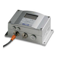
Vaisala BAROCAP PTB330 User Manual (144 pages)
Digital barometer
Brand:
Vaisala
| Category:
Measuring Instruments
| Size: 1.94 MB
Table of Contents
Table of Contents
3
Chapter 1 General Information
11
About this Manual
11
Contents of this Manual
11
Version Information
12
Documentation Conventions
12
Table 1 Manual Revisions
12
Safety
13
ESD Protection
13
Recycling
14
Trademarks
14
License Agreement
14
Warranty
14
Chapter 2 Product Overview
15
Introduction to PTB330
15
Basic Features and Options
16
Pressure Measurement
16
Outer Structure of the Barometer
17
Figure 1 Barometer Body
17
Table 2 Quantities Measured by PTB330
17
Inner Structure of the Barometer
18
Figure 2 Open Barometer Interior
18
Chapter 3 Installation
19
Mounting the Housing
19
Standard Mounting Without Mounting Plate
19
Figure 3 Standard Mounting
19
Wall Mounting with Wall Mounting Kit
20
Figure 4 Mounting with Wall Mounting Kit
20
Figure 5 Dimensions of Plastic Mounting Plate
20
Mounting with DIN Rail Installation Kit
21
Pole Installation with Installation Kit for Pole or Pipeline
21
Figure 6 Mounting with DIN Rail Installation Kit
21
Figure 7 Vertical Pole (Side)
22
Figure 8 Vertical Pole (Front)
22
Figure 9 Horizontal Pole
22
Figure 10 Mounting with Metal Wall Mounting Plate
23
Figure 11 Dimensions of Metal Mounting Plate (MM)
23
Mounting Rain Shield with Installation Kit
24
Panel Mounting Frame
24
Figure 12 Mounting Rain Shield with Installation Kit
24
Figure 13 Panel Mounting Frame
25
Figure 14 Panel Mounting Dimensions
25
Pressure Connections
26
General about Wiring and Grounding
27
Cable Bushings
27
Figure 15 Cable Bushings
27
Grounding the Cables
28
Figure 16 Grounding the Screen of Electrical Cable
28
Grounding the Barometer Housing
29
Alternate Wiring Systems
29
Signal and Power Supply Wiring
30
Figure 17 Screw Terminal Block on Motherboard
30
M-12 (8-Pin) Connector
32
Figure 18 Wiring of Optional M-12 (8-Pin) Connector
32
Table 3 Pin Assignments to RS-232-/485 Serial Output
32
D-9 Connector
33
Figure 19 Wiring of Optional D-9 Connector
33
Table 4 Pin Assignments to RS-232/485 Serial Output
33
Optional Modules
34
AC Power Supply Module
34
Figure 20 AC Power Supply Module
34
Installation
35
Warnings
36
Galvanic Isolation for Output
39
Figure 21 Galvanic Power Isolation
39
Analog Output Module AOUT-1T
40
Figure 22 Analog Output 1 Module AOUT-1T
40
Installation and Wiring
40
Figure 23 Analog Output Dip Switch Positions
41
Relay Module RELAY-1L
42
Installation and Wiring
42
Selecting the Activation State of the Relay
43
Figure 24 Relay Module
43
RS-422/RS-485 Interface Module (RS485-1)
44
Figure 25 RS485-1 Module
44
Installation and Wiring
45
Figure 26 4-Wire RS-485 Bus
46
Table 5 Connecting the Twisted Pair Wires to the Screw Terminals
46
Figure 27 2-Wire RS-485 Bus
47
Table 6 4-Wire (Switch 3: On)
47
Table 7 2-Wire (Switch 3: Off)
47
Chapter 4 Operation
49
Getting Started
49
Display/Keypad (Optional)
49
Basic Display
49
Figure 28 Basic Display
49
Figure 29 Main Menu (Main Level)
50
Menus and Navigation
50
Pressure 3H Trend and Tendency Reading
51
Figure 30 P 3H Tendency
51
Pressure Tendency Graphics and Codes
51
Using Basic Display
51
Figure 31 Pressure Tendency Description
52
Missing Trend
53
Using Serial Line
53
Graphic History
53
Figure 32 Graphical Display
53
Table 8 Periods for Trend and Max/Min Calculations
54
Table 9 Graph Information Messages in Cursor Mode
54
Information Display
55
Figure 33 Device Information on Display
55
Display Settings
56
Changing Quantities
56
Changing Units
56
Backlight
57
Contrast
57
Keypad Lock
57
Rounding
57
Measuring Settings
58
Diagnostic Settings
58
Serial Interface Settings
59
Figure 34 Checking Stability of the Measurement
59
System Settings
60
Language
60
Menu PIN Lock
60
Clearing Graph Displays
61
Factory Settings
61
Relay Settings
62
Figure 35 Relay Indicators on Display
62
Relay Outputs
62
Testing the Operation of Relays
63
Analog Output Settings
64
Analog Output Quantities
64
Testing the Operation of Analog Outputs
64
Analog Output Fault Indication
65
MI70 Link Interface Software for Data Handling
65
Serial Line Communication
66
Figure 36 Service Port Connector and User Port Terminal on Motherboard
66
Figure 37 Connection Example between PC Serial Port and User Port
67
Table 10 Default Serial Communication Settings for the User Port
67
User Port Connection
67
Service Port Connection
68
Table 11 Fixed Communication Settings for Service Port
68
Terminal Program Settings
68
Figure 38 Opening a Serial Connection
69
Opening a Serial/Usb Connection
69
List of Serial Commands
70
General Settings
72
Changing Quantities and Units
72
Form
72
Table 12 FORM Modifiers
73
Table 13 Symbols Used in FORM Checksum Equations
74
Table 14 Quantity Symbols
74
Table 15 Output Quantities and Units
75
Unit
75
DATE and TIME
77
Measurement Related Commands
79
Tqfe
79
Dpmax
80
Avrg
81
Hhcp
81
Hqfe
82
Hqnh
82
Icaoqnh
83
Pstab
84
User Port Serial Settings
86
Sdelay
86
Seri
86
Smode
87
Table 16 Selection of Output Modes
87
Echo
88
Intv
88
System Information Commands
89
Errs
89
Vers
90
Resetting Barometer by Using Serial Line
90
Reset
90
Table 17 ERRS Command Line Parameters
90
Locking Menu/Keypad by Using Serial Line
91
Lock
91
Data Recording
92
Selecting Data Recording Quantities
92
Dsel
92
View Recorded Data
93
Dir
93
Play
94
Delete/Undelete
95
Operating Relays
95
Quantity for Relay Output
95
Measurement-Based Relay Output Modes
95
Relay Setpoints
95
Figure 39 Relay Output Modes
96
Hysteresis
97
Relay Indicating Barometer Error Status
97
Figure 40 FAULT STATUS Relay Output Mode
97
Enabling/Disabling Relays
98
Setting Relay Outputs
98
Rsel
98
Testing the Operation of Relays
100
Rtest
100
Operating RS-485 Module
101
Networking Commands
101
Addr
102
Scom
102
Sdelay
102
Smode Poll
102
Close
103
Open
103
Send
103
Operating Analog Output
104
Changing Output Mode and Range
104
Figure 41 Current/Voltage Switches of Output Module
104
Figure 42 Dip Switch Selection Example
105
Analog Output Quantities
106
Amode/Asel
106
Analog Output Tests
107
Atest
107
Analog Output Fault Indication Setting
107
Aerr
107
Chapter 5 Maintenance
109
Periodic Maintenance
109
Cleaning
109
Error States
109
Figure 43 Error Indicator and Error Message
110
Table 18 Error Messages
111
Technical Support
112
Product Returns
112
Chapter 6
113
Calibration and Adjustment
113
Pressure
113
Opening and Closing the Adjustment Mode
114
Figure 44 Adjustment Menu
114
Table 19 Adjustment and Calibration Commands for Barometer Module P1
114
Pressure Adjustment
115
Figure 45 PTB330 Adjustments
115
Adjustments Using Display/Keypad
116
Lcp1, Lcp2, Lcp3
118
Linear/Offset Adjustment Using Serial Line
118
Mpcp1, Mpcp2, Mpcp3
120
Multipoint Adjustment Using Serial Line
120
Analog Output Adjustment (Ch1)
123
Using Display/Keypad
123
Using Serial Line
124
Acal
124
Feeding Adjustment Information
125
Using Display/Keypad
125
Using Serial Line
125
Cdate
125
Ctext
125
Chapter 7
127
Technical Data
127
Specifications
127
Performance
127
Barometric Pressure Range 50
127
Barometric Pressure Range 500
127
Table 20 Barometric Pressure Range 500
127
Table 21 Barometric Pressure Range 50
127
Operating Environment
128
Table 22 Temperature Dependence
128
Table 23 Total Accuracy at -40
128
Table 24 Long Term Stability
128
Table 25 Operating Environment
128
Inputs and Outputs
129
Table 26 Inputs and Outputs
129
Mechanics
130
Technical Specifications of Optional Modules
130
Table 27 Mechanics
130
Table 28 AC Power Supply Module
130
Table 29 Analog Output Module AOUT-1
130
Table 30 Relay Module
131
Table 31 RS-422/RS-485 Module RS485-1
131
Options and Accessories
132
Table 32 Options and Accessories
132
Dimensions (in MM)
133
Figure 46 Barometer Body Dimensions
133
Appendix A Calculation Formulas
135
ICAOQNH Mode for QNH and QFE
136
Table 33 Symbols Used in QNH Calculation Formulas
136
Appendix B
137
Figure 47 Pressure Conversion Chart
137
Unit Conversion Tables
137
Table 34 Unit Conversion Table for All Pressure Quantities
138
Table 35 Unit Conversion Table for Difference Pressure ΔP
138
Table 36 Unit Conversion Table for Settings Pressure Stability PSTAB and Maximum Pressure Difference ΔPMAX
138
Table 37 Unit Conversion Table for Settings HHCP and HQFE
139
Table 38 Unit Conversion Table for Settings HQNH
139
Table 39 Unit Conversion Table for Setting TQFE
139
Appendix Cpa11A Emulation Mode
141
Activating the PA11A Emulation Mode
141
PA11A Message Format
142
Advertisement
Vaisala BAROCAP PTB330 User Manual (139 pages)
Digital Barometer
Brand:
Vaisala
| Category:
Weather Station
| Size: 2.82 MB
Table of Contents
Table of Contents
3
About this Manual
13
Contents of this Manual
13
General Information
13
Feedback
14
General Safety Considerations
14
ESD Protection
15
Product Related Safety Precautions
15
License Agreement
16
Recycling
16
Trademarks
16
Warranty
17
Chapter 2 Product Overview
19
Introduction to PTB330
19
Basic Features and Options
19
Pressure Measurement
20
Table 1 Quantities Measured by PTB330
20
Outer Structure of the Barometer
21
Figure 1 Barometer Body
21
Inner Structure of the Barometer
22
Figure 2 Inside of Open Barometer
22
Chapter 3 Installation
23
Mounting the Housing
23
Standard Mounting Without Mounting Plate
23
Wall Mounting with Wall Mounting Kit
24
Figure 3 Standard Mounting
24
Figure 4 Mounting with Wall Mounting Kit
24
Mounting with DIN Rail Installation Kit
25
Figure 5 Dimensions of Plastic Mounting Plate
25
Figure 6 Mounting with DIN Rail Installation Kit
25
Pole Installation with Installation Kit for Pole or Pipeline
26
Figure 7 Vertical Pole (Side)
26
Figure 8 Vertical Pole (Front)
26
Figure 9 Horizontal Pole
27
Figure 10 Mounting with Metal Wall Mounting Plate
27
Mounting Rain Shield with Installation Kit
28
Figure 11 Dimensions of Metal Mounting Plate (MM)
28
Figure 12 Mounting Rain Shield with Installation Kit
28
Panel Mounting Frame
29
Figure 13 Panel Mounting Frame
29
General about Wiring and Grounding
30
Cable Bushings
30
Figure 14 Panel Mounting Dimensions
30
Figure 15 Cable Bushings
31
Grounding the Cables
32
Figure 16 Grounding the Screen of Electrical Cable
32
Grounding the Barometer Housing
33
Alternate Wiring Systems
33
Signal and Power Supply Wiring
34
Figure 17 Screw Terminal Block on Motherboard
34
M-12 (8-Pin) Connector
36
Figure 18 Wiring of Optional M-12 (8-Pin) Connector
36
Table 2 Pin Assignments to RS-232-/485 Serial Output
36
D-9 Connector
37
Figure 19 Wiring of Optional D-9 Connector
37
Table 3 Pin Assignments to RS-232/485 Serial Output
37
Optional Modules
38
AC Power Supply Module
38
Figure 20 AC Power Supply Module
38
Installation
39
Warnings
40
Galvanic Isolation for Output
43
Figure 21 Galvanic Output Isolation
43
Analog Output Module
44
Installation and Wiring
44
Figure 22 Analog Output 1 Module
44
Relay Module (RELAY-1)
45
Installation and Wiring
45
Figure 23 Analog Output
45
Selecting the Activation State of the Relay
46
Figure 24 Relay Module
47
RS-422/485-1 Interface Module
48
Installation and Wiring
48
Figure 25 RS-485-1 Module
48
Table 4 Connecting the Twisted Pair Wires to the Screw Terminals
49
Figure 26 4-Wire RS-485 Bus
50
Table 5 4-Wire (Switch 3:On)
50
Figure 27 2-Wire RS-485 Bus
51
Table 6 2-Wire (Switch 3:Off)
51
Chapter 4 Operation
53
Getting Started
53
Display/Keypad (Optional)
53
Basic Display
53
Menus and Navigation
54
Figure 28 Basic Display
54
Pressure 3H Trend and Tendency Reading
55
Using Basic Display
55
Pressure Tendency Graphics and Codes
55
Figure 29 Main Menu (Main Level)
55
Figure 30 P3H Tendency
55
Figure 31 Pressure Tendency Description
56
Using Serial Line
57
Missing Trend
57
Graphic History
57
Figure 32 Graphical Display
58
Table 7 Periods for Trend and Max/Min Calculations
58
Table 8 Graph Information Messages in Cursor Mode
58
Information Display
59
Figure 33 Device Information on Display
59
Display Settings
60
Changing Quantities
60
Changing Units
60
Rounding
61
Backlight
61
Contrast
61
Keypad Lock
61
Measuring Settings
62
Diagnostic Settings
62
Serial Interface Settings
63
Figure 34 Checking Stability of the Measurement
63
System Settings
64
Language
64
Menu PIN Lock
64
Factory Settings
65
Clearing Graph Displays
65
Relay Settings
66
Relay Outputs
66
Figure 35 Relay Indicators on Display
66
Testing the Operation of Relays
67
Analog Output Settings
68
Analog Output Quantities
68
Testing the Operation of Analog Outputs
68
Analog Output Fault Indication
69
MI70 Link Interface Software for Data Handling
70
Serial Line Communication
70
User Port Connection
71
Figure 36 Service Port Connector and User Port Terminal on
71
Table 9 Default Serial Communication Settings for the User Port
71
Figure 37 Connection Example between PC Serial Port and User Port
72
Service Port Connection
73
Terminal Program Settings
73
Table 10 Fixed Communication Settings for Service Port
73
Figure 38 Starting Hyper Terminal Connection
74
Figure 39 Connecting to Hyper Terminal
74
List of Serial Commands
75
Figure 40 Hyper Terminal Serial Port Settings
75
General Settings
78
Changing Quantities and Units
78
Using Serial Line
79
Table 11 the Modifiers
79
Unit
80
Table 12 Output Quantities and Units
80
Measurement Related Commands
81
Tqfe
81
Dpmax
81
Hhcp
82
Hqfe
82
Hqnh
82
Pstab
83
User Port Serial Settings
83
Using Serial Line
83
Smode
84
Intv
84
Echo
84
Table 13 Selection of Output Modes
84
System Information Commands
85
Errs
86
Vers
86
Resetting Barometer by Using Serial Line
86
Reset
86
Locking Menu/Keypad by Using Serial Line
87
Lock
87
Data Recording
88
Selecting Data Recording Quantities
88
Dsel
88
View Recorded Data
89
Dir
89
Play
90
Delete/Undelete
90
Operation of Relays
91
Quantity for Relay Output
91
Measurement-Based Relay Output Modes
91
Relay Setpoints
91
Hysteresis
92
Figure 41 Relay Output Modes
92
Relay Indicating Barometer Error Status
93
Enabling/Disabling Relays
94
Figure 42 FAULT/ONLINE STATUS Relay Output Modes
94
Setting Relay Outputs
95
Rsel
95
Testing Operation of Relays
96
Rtest
96
Operation of RS-485 Module
97
Networking Commands
97
Sdelay
97
Seri
98
Echo
98
Smode
98
Intv
99
Addr
99
Send
100
Scom
100
Open
100
Close
101
Operation of Analog Output
101
Changing Output Mode and Range
101
Figure 43 Current/Voltage Switches of Output Modules
102
Figure 44 Dip Switch Selection Example
102
Analog Output Quantities
103
Analog Output Tests
104
Atest
104
Analog Output Fault Indication Setting
104
Chapter 5 Maintenance
105
Periodic Maintenance
105
Cleaning
105
Error States
105
Figure 45 Error Indicator and Error Message
106
Table 14 Error Messages
106
Calibration and Adjustment
109
Pressure
109
Opening and Closing the Adjustment Mode
110
Table 15 Adjustment and Calibration Commands for Barometer
110
Pressure Adjustment
111
Figure 46 Adjustment Menu
111
Figure 47 PTB330 Adjustments
111
Adjustments Using Display/Keypad
112
1-Point Adjustment Using Serial Line
113
Lcp1
113
Mpcp1
114
Analog Output Adjustment (Ch1)
115
Using Display/Keypad
116
Using Serial Line
116
Feeding Adjustment Information
117
Using Display/Keypad
117
Using Serial Line
117
Chapter 7 Technical Data
119
Specifications
119
Performance
119
Barometric Pressure Range 500
119
Barometric Pressure Range 50
119
Table 16 Barometric Pressure Range 500
119
Table 17 Barometric Pressure Range 50
119
Operating Environment
120
Table 21 Operating Environment
120
Table 18 Temperature Dependence
120
Table 19 Total Accuracy at -40
120
Table 20 Long Term Stability
120
Inputs and Outputs
121
Table 22 Inputs and Outputs
121
Mechanics
122
Technical Specifications of Optional Modules
122
Table 23 Mechanics
122
Table 24 AC Power Supply Module
122
Table 25 Analog Output Module AOUT-1
122
Table 26 Relay Module
123
Table 27 RS-485 Module
123
Options and Accessories
124
Table 28 Options and Accessories
124
Dimensions (in MM)
125
Technical Support
125
Figure 48 Barometer Body Dimensions
125
Return Instructions
126
Vaisala Service Centers
127
Appendix Acalculation Formulas
129
Unit Conversion Tables
131
Figure 49 Pressure Conversion Chart
131
Table 29 Unit Conversion Table for All Pressure Quantities
132
Table 30 Unit Conversion Table for Difference Pressure Deltap and
132
Table 31 Unit Conversion Table for Settings Pressure Stability PSTAB
132
Table 32 Unit Conversion Table for Settings HHCP and HQFE
133
Table 33 Unit Conversion Table for Settings HQNH
133
Table 34 Unit Conversion Table for Setting TQFE
133
Appendix Cpa11A Emulation Mode
135
Activating the PA11A Emulation Mode
135
PA11A Message Format
136
Advertisement
Related Products
Vaisala K-PATENTS PR-21-S
Vaisala K-PATENTS PR-43-AX Series
Vaisala K-PATENTS PR-43-AP
Vaisala K-PATENTS PR-23-AP
Vaisala K-PATENTS PR-23-GP
Vaisala K-PATENTS PR-23-GC
Vaisala K-PATENTS PR-23-RP
Vaisala K-PATENTS PR-23-M
Vaisala K-PATENTS PR-23-W
Vaisala K-PATENTS PR-23 AX Series
Vaisala Categories
Transmitter
Measuring Instruments
Accessories
Test Equipment
Weather Station
More Vaisala Manuals
Login
Sign In
OR
Sign in with Facebook
Sign in with Google
Upload manual
Upload from disk
Upload from URL