Sign In
Upload
Download
Add to my manuals
Delete from my manuals
Share
URL of this page:
HTML Link:
Bookmark this page
Add
Manual will be automatically added to "My Manuals"
Print this page
×
Bookmark added
×
Added to my manuals
Manuals
Brands
ESAB Manuals
Welding System
Caddy 130
Service manual
ESAB Caddy 130 Service Manual
Hide thumbs
1
2
3
4
5
6
7
8
9
10
11
12
13
14
15
16
17
18
19
20
21
22
23
24
25
26
27
28
29
30
31
32
33
34
35
36
page
of
36
Go
/
36
Bookmarks
Advertisement
Quick Links
Download this manual
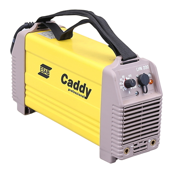
LHN 130/140/200
Caddy 130/140/200
cmha2p00
Service manual
0740 800 043
040906
Valid for serial no. 301- -xxx- -xxxx to 220- -xxx- -xxxx
Previous
Page
Next
Page
1
2
3
4
5
Advertisement
Need help?
Do you have a question about the Caddy 130 and is the answer not in the manual?
Ask a question
Questions and answers
Related Manuals for ESAB Caddy 130
Welding System ESAB Caddy 140 Instruction Manual
(12 pages)
Welding System ESAB CaddyTig HF Service Manual
(26 pages)
Welding System Esab CaddyTig HF Instruction Manual
(11 pages)
Welding System ESAB Caddy Professional 250 Instruction Manual
(16 pages)
Welding System ESAB CaddyArc 150 Instruction Manual
(18 pages)
Welding System ESAB Caddy 150 Instruction Manual
(16 pages)
Welding System ESAB Caddy Tig 1500i TA34 Service Manual
(50 pages)
Welding System ESAB Caddy Tig 2200i TA34 Service Manual
(50 pages)
Welding System ESAB Caddy Tig 2200i TA33 Service Manual
(50 pages)
Welding System ESAB Caddy Series Instruction Manual
(26 pages)
Welding System ESAB ESABMig C280 Instruction Manual
(24 pages)
Welding System ESAB ESABMig C420 Instruction Manual
(46 pages)
Welding System ESAB ESABMig C240 Instruction Manual
(20 pages)
Welding System ESAB OXWELD C-62 Instructions Manual
Cutting torch and powder-washing attachment (9 pages)
Welding System ESAB CIGWELD EasyWeld 130 Operating Manual
(66 pages)
Welding System ESAB Cigweld EasyWeld 160 Operating Manual
(84 pages)
This manual is also suitable for:
Caddy 140
Caddy 200
Lhn 130
Lhn 140
Lhn 200
Print
Rename the bookmark
Delete bookmark?
Delete from my manuals?
Login
Sign In
OR
Sign in with Facebook
Sign in with Google
Upload manual
Upload from disk
Upload from URL


Need help?
Do you have a question about the Caddy 130 and is the answer not in the manual?
Questions and answers