Table of Contents
Advertisement
Quick Links
One Technology Way • P.O. Box 9106 • Norwood, MA 02062-9106, U.S.A. • Tel: 781.329.4700 • Fax: 781.461.3113 • www.analog.com
Evaluating the ADG5209F, Overvoltage Protected Dual 4:1 Multiplexer
FEATURES
Supply voltages
Dual supply: ±5 V to ±22 V
Single supply: 8 V to 44 V
Protected against overvoltage on source pins
Signal voltages up to −55 V and +55 V
Parallel interface compatible with 3 V logic
On-board low dropout (LDO) regulator for digital supply and
control, if required
EVALUATION KIT CONTENTS
EVAL-ADG5209FEBZ
evaluation board
ONLINE RESOURCES
Documents Needed
ADG5209F
data sheet
EVAL-ADG5209FEBZ
user guide
EQUIPMENT NEEDED
DC voltage source
±22 V for dual supply
44 V for single supply
Optional digital logic supply: 3 V to 5 V
Analog signal source
Method to measure voltage, such as a digital multimeter (DMM)
PLEASE SEE THE LAST PAGE FOR AN IMPORTANT
WARNING AND LEGAL TERMS AND CONDITIONS.
TYPICAL EVALUATION SETUP
Figure 1.
EVAL-ADG5209FEBZ
(on Right), Power Supply, and Signal Generator
Rev. 0 | Page 1 of 12
EVAL-ADG5209FEBZ User Guide
GENERAL DESCRIPTION
The
EVAL-ADG5209FEBZ
ADG5209F
and features an overvoltage protected dual 4:1
multiplexer. The
ADG5209F
protection circuitry on the source pins and is protected against
signals up to −55 V and +55 V in both the powered and
unpowered states.
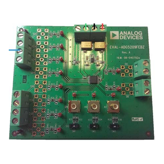
Figure 1 shows the
EVAL-ADG5209FEBZ
setup. The
ADG5209F
is soldered to the center of the evaluation
board, and wire screw terminals are provided to connect to each
of the source and drain pins. Three screw terminals are used to
power the device, with a fourth terminal used to provide a user
defined digital logic supply voltage, if required. Alternatively, a
low dropout (LDO) regulator is provided for 5 V digital logic
supply.
Full specifications on the
ADG5209F
ADG5209F
data sheet, which should be consulted in
conjunction with this user guide when using the evaluation
board.
UG-875
is the evaluation board for the
has overvoltage detection and
in a typical evaluation
are available in the
Advertisement
Table of Contents

Related Manuals for Analog Devices EVAL-ADG5209FEBZ


Summary of Contents for Analog Devices EVAL-ADG5209FEBZ
-
Page 1: Features
EVAL-ADG5209FEBZ User Guide UG-875 One Technology Way • P.O. Box 9106 • Norwood, MA 02062-9106, U.S.A. • Tel: 781.329.4700 • Fax: 781.461.3113 • www.analog.com Evaluating the ADG5209F, Overvoltage Protected Dual 4:1 Multiplexer FEATURES GENERAL DESCRIPTION Supply voltages EVAL-ADG5209FEBZ is the evaluation board for the Dual supply: ±5 V to ±22 V... -
Page 2: Table Of Contents
UG-875 EVAL-ADG5209FEBZ User Guide TABLE OF CONTENTS Features ....................1 Evaluation Board Hardware .............4 Evaluation Kit Contents ..............1 Power Supply ..................4 Online Resources ................1 Input Signals...................4 Equipment Needed ................1 Jumper Settings ..................5 General Description ................. 1 Switches and 0 Ω Resistors ............5 Typical Evaluation Setup .............. -
Page 3: Getting Started
EVAL-ADG5209FEBZ User Guide UG-875 GETTING STARTED EVALUATION BOARD SETUP PROCEDURE A functionality test can be set up as follows: EVAL-ADG5209FEBZ evaluation board is designed to Connect a power supply to J5. Connect VSS and GND together if a single supply is required. -
Page 4: Evaluation Board Hardware
UG-875 EVAL-ADG5209FEBZ User Guide EVALUATION BOARD HARDWARE The operation of the ADG5209F is evaluated using the EVAL- INPUT SIGNALS ADG5209FEBZ. Figure 1 shows a typical evaluation setup Four screw connectors are provided to connect to both where only a power supply and signal generator are required. -
Page 5: Jumper Settings
EVAL-ADG5209FEBZ User Guide UG-875 JUMPER SETTINGS SWITCHES AND 0 Ω RESISTORS Table 1. ADG5209F Truth Table Switches are used to control the ADG5209F manually and SW1 (EN) SW2 (A0) SW3 (A1) Connected Sx 0 Ω resistors are used to configure the digital control voltage. -
Page 6: Evaluation Board Schematics And Artwork
UG-875 EVAL-ADG5209FEBZ User Guide EVALUATION BOARD SCHEMATICS AND ARTWORK Figure 3. ADG5209F Evaluation Board Schematic (Part 1) Rev. 0 | Page 6 of 12... - Page 7 EVAL-ADG5209FEBZ User Guide UG-875 Figure 4. ADG5209F Evaluation Board Schematic (Part 2) Figure 5. ADG5209F Evaluation Board Schematic (Part 3) Rev. 0 | Page 7 of 12...
- Page 8 UG-875 EVAL-ADG5209FEBZ User Guide Figure 6. EVAL-ADG5209FEBZ Silkscreen Figure 7. EVAL-ADG5209FEBZ Top Layer Rev. 0 | Page 8 of 12...
- Page 9 EVAL-ADG5209FEBZ User Guide UG-875 Figure 8. EVAL-ADG5209FEBZ Layer 2 Figure 9. EVAL-ADG5209FEBZ Layer 3 Rev. 0 | Page 9 of 12...
- Page 10 UG-875 EVAL-ADG5209FEBZ User Guide Figure 10. EVAL-ADG5209FEBZ Bottom Layer Rev. 0 | Page 10 of 12...
-
Page 11: Ordering Information
EVAL-ADG5209FEBZ User Guide UG-875 ORDERING INFORMATION BILL OF MATERIALS Table 3. Manufacturer Part Reference Designator Description Number Stock Code A0, A1, EN 50 Ω, straight, SMB jack SMB1251B1-3GT30G-50 FEC 1111349 C3, C4, C7, C8 50 V, X7R, 0603 size, 0.1 µF, multilayer... - Page 12 By using the evaluation board discussed herein (together with any tools, components documentation or support materials, the “Evaluation Board”), you are agreeing to be bound by the terms and conditions set forth below (“Agreement”) unless you have purchased the Evaluation Board, in which case the Analog Devices Standard Terms and Conditions of Sale shall govern. Do not use the Evaluation Board until you have read and agreed to the Agreement.
- Page 13 Mouser Electronics Authorized Distributor Click to View Pricing, Inventory, Delivery & Lifecycle Information: Analog Devices Inc. EVAL-ADG5209FEBZ...
Need help?
Do you have a question about the EVAL-ADG5209FEBZ and is the answer not in the manual?
Questions and answers