Table of Contents
Advertisement
Quick Links
One Technology Way • P.O. Box 9106 • Norwood, MA 02062-9106, U.S.A. • Tel: 781.329.4700 • Fax: 781.461.3113 • www.analog.com
Evaluation Board for the
FEATURES
SPI interface with error detection
Includes CRC, invalid read/write address, and SCLK count
error detection
Analog supply voltages
Dual-supply: ±3.3 V to ±8 V
Single-supply: 3.3 V to 16 V
PC control in conjunction with the evaluation software
EVAL-SDP-CB1Z
SDP
PACKAGE CONTENTS
EVAL-ADGS1612SDZ
DOCUMENTS NEEDED
ADGS1612
data sheet
EQUIPMENT NEEDED
EVAL-SDP-CB1Z
controller board
ACE
software with EVAL-ADGS1612SDZ plug-in
DC voltage source
±5.5 V for dual-supply
12 V, 5V, 3.3V for single-supply
Optional digital logic supply: 3.3 V
Analog signal source
Method to measure voltage, such as a digital multimeter (DMM)
PLEASE SEE THE LAST PAGE FOR AN IMPORTANT
WARNING AND LEGAL TERMS AND CONDITIONS.
ADGS1612
SPI Interface, 1 Ω R
Mux Configurable, Quad SPST Switch
Rev. 0 | Page 1 of 11
EVAL-ADGS1612SDZ
, ±5 V, 12 V, 5 V, 3.3 V,
ON
GENERAL DESCRIPTION
The EVAL-ADGS1612SDZ is the evaluation board for the
ADGS1612. The
ADGS1612
single-throw (SPST) switch controlled by a serial peripheral
interface (SPI). The SPI has robust error detection features. These
are cyclic redundancy check (CRC) error detection, invalid read/
write address detection, and serial clock (SCLK) count error
detection. It is possible to daisy-chain multiple
together. This enables the configuration of multiple devices with a
minimal amount of digital lines. The
burst mode that decreases the time between SPI commands.
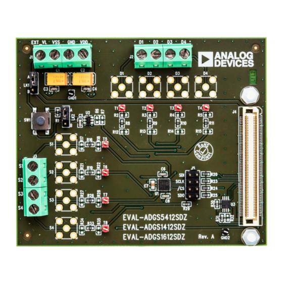
Figure 1 shows the EVAL-ADGS1612SDZ in a typical evaluation
setup. The EVAL-ADGS1612SDZ is controlled by the system
demonstration platform (SDP) which connects to a PC via a USB
port. The
ADGS1612
is on the center of the evaluation board and
wire screw terminals are provided to connect to each of the
source and drain pins. Three screw terminals power the device
and a fourth terminal provides users with a defined digital logic
supply voltage, if required. Alternatively, the digital logic supply
voltage can be supplied from the SDP.
Full specifications on the
ADGS1612
data sheet available from Analog Devices, Inc., and
should be consulted in conjunction with this user guide when
using the evaluation board.
The evaluation board interfaces to the USB port of a PC via the
SDP board. The
EVAL-SDP-CB1Z
board) is available to order on the Analog Devices website at
www.analog.com.
User Guide
UG-1199
is an iCMOS, quad single-pole,
ADGS1612
ADGS1612
also supports
ADGS1612
are available in the
board
(SDP-B
controller
devices
Advertisement
Table of Contents

Related Manuals for Analog Devices EVAL-ADGS1612SDZ


Summary of Contents for Analog Devices EVAL-ADGS1612SDZ
-
Page 1: Features
SDP board. The EVAL-SDP-CB1Z board (SDP-B controller board) is available to order on the Analog Devices website at www.analog.com. PLEASE SEE THE LAST PAGE FOR AN IMPORTANT Rev. 0 | Page 1 of 11 WARNING AND LEGAL TERMS AND CONDITIONS. -
Page 2: Table Of Contents
UG-1199 EVAL-ADGS1612SDZ User Guide TABLE OF CONTENTS Link Options ..................4 Features ....................1 Evaluation Board Software ...............5 Package Contents ................1 Installing the Software ..............5 Documents Needed ................1 Initial Set Up ..................5 Equipment Needed ................1 Block Diagram And Description .............5 General Description ................. -
Page 3: Adgs1612 Evaluation Board Layout
EVAL-ADGS1612SDZ User Guide UG-1199 ADGS1612 EVALUATION BOARD LAYOUT Figure 1. Rev. 0 | Page 3 of 11... -
Page 4: Evaluation Board Hardware
UG-1199 EVAL-ADGS1612SDZ User Guide EVALUATION BOARD HARDWARE A 0 Ω resistor is placed in the signal path and can be replaced POWER SUPPLIES with a user defined value. The resistor, combined with the 0603 Connector J1 provides access to the supply pins of the ADGS1612. -
Page 5: Evaluation Board Software
BLOCK DIAGRAM AND DESCRIPTION board plug-ins appear in the attached hardware section of the Start tab. The EVAL-ADGS1612SDZ software is organized so that it Double-click on the evaluation board plug-in to open the appears similar to the functional block diagram shown in the evaluation board view seen in Figure 2. -
Page 6: Memory Map
UG-1199 EVAL-ADGS1612SDZ User Guide Table 3. Block Diagram Functions Memory Map Label Function All registers are fully accessible from the memory map tab; this The drop-down menus configure SW1 to SW4 as allows registers to be edited at a bit level (see Figure 5 and Figure 6). -
Page 7: Evaluation Board Schematics And Artwork
EVAL-ADGS1612SDZ User Guide UG-1199 EVALUATION BOARD SCHEMATICS AND ARTWORK Figure 7. EVAL-ADGS1612SDZ Schematic 1 Figure 8. EVAL-ADGS1612SDZ Schematic 2 Rev. 0 | Page 7 of 11... - Page 8 UG-1199 EVAL-ADGS1612SDZ User Guide Figure 9. EVAL-ADGS1612SDZ Schematic 3 Figure 10. EVAL-ADGS1612SDZ Silk Screen Rev. 0 | Page 8 of 11...
- Page 9 EVAL-ADGS1612SDZ User Guide UG-1199 Figure 11. EVAL-ADGS1612SDZ Top Layer Figure 12. EVAL-ADGS1612SDZ Layer 2 Rev. 0 | Page 9 of 11...
- Page 10 UG-1199 EVAL-ADGS1612SDZ User Guide Figure 13. EVAL-ADGS1612SDZ Layer 3 Figure 14. EVAL-ADGS1612SDZ Bottom Layer Rev. 0 | Page 10 of 11...
-
Page 11: Ordering Information
(“Agreement”) unless you have purchased the Evaluation Board, in which case the Analog Devices Standard Terms and Conditions of Sale shall govern. Do not use the Evaluation Board until you have read and agreed to the Agreement. Your use of the Evaluation Board shall signify your acceptance of the Agreement. This Agreement is made by and between you (“Customer”) and Analog Devices, Inc.
Need help?
Do you have a question about the EVAL-ADGS1612SDZ and is the answer not in the manual?
Questions and answers