Table of Contents
Advertisement
Quick Links
ViconNet 8.0 Software
Installation Guide
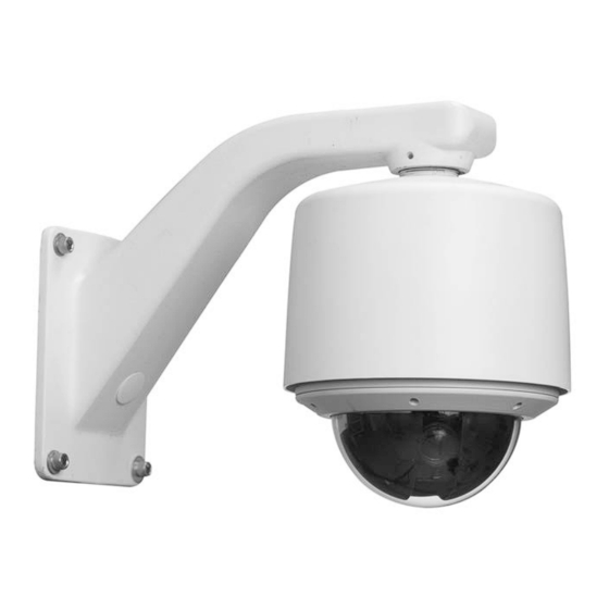
Surveyor® MKII Network Camera Domes
Vicon Industries Inc. does not warrant that the functions contained in this equipment will
meet your requirements or that the operation will be entirely error free or perform
precisely as described in the documentation. This system has not been designed to be
used in life-critical situations and must not be used for this purpose.
Document Number: 8009-8282-00-02 Product specifications subject to change without
notice. Issued: 2/17 Copyright © 2017 Vicon Industries Inc. All rights reserved.
XXYYY-XX-XX
XX282-00-02
Vicon Industries Inc.
Tel: 631-952-2288) Fax: 631-951-2288
Toll Free: 800-645-9116
24-Hour Technical Support: 800-34-VICON
(800-348-4266) UK: 44/(0) 1489-566300
www.vicon-security.com
Advertisement
Table of Contents

Related Manuals for Vicon Surveyor 282-00-02 Series


Summary of Contents for Vicon Surveyor 282-00-02 Series
- Page 1 Surveyor® MKII Network Camera Domes XX282-00-02 Vicon Industries Inc. Vicon Industries Inc. does not warrant that the functions contained in this equipment will Tel: 631-952-2288) Fax: 631-951-2288 meet your requirements or that the operation will be entirely error free or perform Toll Free: 800-645-9116 precisely as described in the documentation.
-
Page 2: Chapter 1 Introduction
Introduction Chapter 1 Introduction This chapter provides general information about Surveyor MKII Network Domes. Refer to the end of this chapter for the organization of the rest of this manual. The chapter consists of the following topics: Topic Page General Information Model Tables Organization of this Manual Surveyor MKII Network Dome... -
Page 3: General Information
H.264 or M-JPEG compression. The dome supports ONVIF Profile S open architecture connectivity to enable integration into third party Video Management Systems (VMS), including Vicon’s Valerus and ViconNet. The Surveyor MKII Network Dome is designed for easy installation and serviceability. - Page 4 Surveyor MKII Network Dome Maintenance and Reference: Describes basic system maintenance, reference information, shipping instructions and technical specifications for the camera dome. Note Always check the Vicon website, www.vicon-security.com, for the latest updated manuals. Surveyor MKII Network Dome...
-
Page 5: Chapter 2 Installation
Chapter 2 Installation Chapter 2 Installation This chapter provides installation information for the Surveyor MKII Network Dome. The chapter consists of the following topics: Topic Page Installation Quick Installation Detailed Installation 2-11 Surveyor MKII HD Network Dome... -
Page 6: How To Use This Manual
Installation Installation Caution This unit should only be installed by a qualified technician using common hand tools and approved materials and wiring methods in accordance with the National Electrical Code ANSI/NFPA 70, state and local wiring codes. All interconnecting equipment or accessories must be UL Listed. Any mention in this manual of alarm inputs/outputs have not been evaluated by UL to be used for burglar alarm functionality. -
Page 7: Accessory Kits
Refer to the Wiring section of this manual for details on using the supplied removable termination blocks. Unpacking All Vicon equipment is tested and inspected before leaving the factory. It is the carrier’s responsibility to provide suitable delivery. Inspect the cartons upon delivery and, if damage is present, make detailed notes on the carrier’s bill. - Page 8 Installation Components All Surveyor MKII units are comprised of a Housing, a Camera Drive, a Shroud and a Lower Dome. These components may be packed in separate boxes within the main box. Housing The housing for the Surveyor MKII outdoor pendant configuration has a die- cast aluminum housing with a sunshield.
-
Page 9: Mac Address
Chapter 2 Installation MAC Address Each IP camera has a unique MAC address. This information is essential in the camera configuration process. Before starting installation, make a record of the IP address and location of the camera. The MAC address is located as shown in the illustration below, under the connector on the mechanism. -
Page 10: Quick Installation
Installation Quick Installation Surveyor MKII HD Network Dome... -
Page 11: Detailed Installation
Pendant Mount Installation The outdoor and high-impact pendant models mount on a variety of Vicon mounts or a 1.5-inch vertical pipe with an appropriate coupling. The pipe is a standard 1.5-inch NPT type and must be oriented vertically so the Surveyor MKII can effectively hang from the pipe. - Page 12 2-11 Installation 5. Apply the provided anti-seize lubricant to the first 2-3 unpainted threads of the housing. 6. Lift the housing/sunshield up to the mount and feed the cables through its top opening. 7. Place the housing onto the 1.5-inch pipe and screw clockwise, looking up at the housing.
- Page 13 2-12 Chapter 2 Installation 13. Lift the Surveyor MKII camera drive up to the housing and attach the housing’s safety cord clip to the camera drive’s tab. See Figure below. Allow the drive to hang from the housing. 14. Align the tabs on the camera drive with the slots in the housing, matching up the arrows on the camera drive and the housing.
-
Page 14: Accessing The Sd Card
2-13 Installation 17. On the outdoor unit, tighten the 4 trim ring captive screws to hold the lower dome in place. Verify proper orientation of the grommet. On the impact-resistant version, there are 6 screws. 18. Proceed to the Operation section of this manual. Accessing the SD Card The SD card slot is on the camera board right under the lens block. -
Page 15: Chapter 3 Wiring
3-14 Chapter 3 Wiring Chapter 3 Wiring This chapter will describe how to wire, configure and operate the Surveyor MKII Network Dome. The chapter consists of the following topics: Topic Page Wiring the Surveyor MKII Network Dome ........... 3-16 Typical Relay and Alarm Connections ............3-17 Installing the Cables .................. -
Page 16: Wiring The Surveyor Mkii Network Dome
3-15 Wiring Wiring the Surveyor MKII Network Dome Wiring is done with runs of cable for power, network and control. Optional wiring can be installed for the alarm input. Refer to the Technical Information section for all electrical requirements. Power Power cables carry AC power and are usually a two-conductor type ranging in size from 20 to 16 AWG. -
Page 17: Typical Relay And Alarm Connections
3-16 Chapter 3 Wiring Typical Relay and Alarm Connections Alarm input and relay output type signals are also carried on individually- shielded twisted-pair cable sets. The signals are defined in the following descriptions. Note The twisted-pair cable should have a wire gauge (AWG) of 24-16 and a category type of 2, 3, 4, 5 or better. - Page 18 3-17 Wiring Since dry contact switches are normally defined in terms of their inactive or “normal” state, the following holds true: NORMALLY CLOSED (NC) = ACTIVE HIGH (OPEN) NORMALLY OPEN (NO) = ACTIVE LOW (CLOSED) To Dome The “active” state can be programmed through the Surveyor MKII web browser interface.
-
Page 19: Installing The Cables
3-18 Chapter 3 Wiring Installing the Cables Warning Disable the AC power to prevent installer injury and damage to the unit. Cables are routed from the inside of the housing to the customer interface board. There should be minimal wire slack at all connection points. After wiring is complete, dress the cables so they are up over the board. - Page 20 3-19 Wiring Table 3: Wiring Connections CONNECTOR/PIN CONNECTOR TYPE CONNECTOR/PIN LABEL SIGNAL NAME NUMBER TERMINAL BLOCK POWER (J2) J2-1 J2-2 Neutral TERMINAL BLOCK ALARM (J11) J11-1 ALARM 1 Alarm I/O 1 J11-2 Ground J11-3 ALARM 2 Alarm I/O 2 J11-4 Ground J11-5 ALARM 3...
-
Page 21: Communication Ports
3-20 Chapter 3 Wiring Communication Ports If using NTCIP protocol, communicate to the Surveyor MKII using ports 3000/UDP or 3001/TCP. If using ONVIF, use port 8000. This is set in the web browser. Surveyor MKII HD Network Dome... -
Page 22: Chapter 4 Operation, Maintenance And Reference
This chapter provides Operation instructions, Maintenance information, cable recommendations and technical specifications for the Surveyor MKII Network Dome. The chapter consists of the following topics: Topic Page Operation 4-24 Maintenance 4-25 Shipping Instructions 4-27 Technical Specifications 4-30 Vicon Standard Equipment Warranty 4-33 Surveyor MKII HD Network Dome... - Page 23 The Surveyor MKII Dome operates on an Onvif Profile S compliant platform that allows it to work with any Onvif compliant Video Management System (VMS), including Vicon’s Valerus and ViconNet. Refer to the documentation for those operating systems to setup the Surveyor MKII.
-
Page 24: Maintenance
4-23 Operation, Maintenance and Reference Maintenance The Surveyor MKII requires no scheduled maintenance; however, the lower domes require occasional cleaning. The clear and smoked domes are referred to as acrylic type domes. The chrome and gold domes are referred to as metallized type domes. All domes require careful handling and occasional cleaning. -
Page 25: Fuse Replacement
4-24 Chapter 4 Operation, Maintenance and Reference Fuse Replacement The Surveyor MKII has one 3 A, 60 V fuse on the CI board. Be sure to use a fuse of the same value if it is necessary to replace the fuse. Surveyor MKII HD Network Dome... -
Page 26: Shipping Instructions
Shipping Instructions Use the following procedure when returning a unit to the factory: 1. Call or write Vicon for a Return Authorization (R.A.) at one of the locations listed below. Record the name of the Vicon employee who issued the R.A. -
Page 27: Network Cable
Chapter 4 Operation, Maintenance and Reference Network Cable Caution Careful selection of proper cable is essential to obtain the best performance. Vicon assumes no responsibility for poor performance when cables other than the recommended types, or equivalent, are used. Vicon recommends using shielded cable. Materials Use pure copper stranded conductors to obtain a low DC resistance. -
Page 28: Inch Pipe Designation
4-27 Operation, Maintenance and Reference 1.5-inch Pipe Designation The standard “1.5-inch pipe” referred to in this manual has actual dimensions Outside diameter: 1.9 inches (48.3 mm). Inside diameter: 1.61 inches (40.9 mm). Wall thickness: 0.145 inches (3.37 mm) minimum (ANSI “standard” grade thickness). -
Page 29: Technical Specifications
10 concurrent sessions maximum Video Output: 1920 x 1080 @ 30 fps Programming Interface: ONVIF or Vicon API Protocols: IPv4/IPv6, TCP, UDP, IGMP, DHCP, FTP, SNMP(v3), SMTP, NTP, RTP, RTSP, RTCP, HTTP, HTTPS, TSL, SSL, 802.1X, QoS, PPPoE, DNS, ARP, ICMP, DDNS, UPnP... - Page 30 4-29 Operation, Maintenance and Reference White Balance: AUTO/MANU/MERC/SODI Shutter: Auto (1/2 ~ 1/30000s, adjustable) Focal Length: 4.4 - 132mm Aperture: f/1.4 (wide) - f/4.6 (tele) Angle of View: Horizontal: 63.4° wide, 2.3° tele Operational Drive Type: Electrical motorized pan and tilt with electronic control Pan View: 360°...
- Page 31 4-30 Chapter 4 Operation, Maintenance and Reference Storage Temperature Range: -40 to 150° F (-40 to 65° C) Storage Humidity Range: 0 to 90% relative, non-condensing Compliance: International Protection (IP) Rating IP66; NEMA 4X; NEMA TS2-2003 V02.06 Maximum Power Cable Distances Table Wire Size (AWG) Annealed Copper...
-
Page 32: Vicon Standard Equipment Warranty
“autopan” or “tour” modes of operation. Such continuous operation is outside the scope of this warranty. 11. Any product sold as “special” or not listed in Vicon’s commercial price list: One year from date of original retail purchase. - Page 33 Except as provided in this written warranty and to the extent permitted by law, neither Vicon nor any affiliated shall be liable for any loss, (including loss of data and information), inconvenience, or damage, including, but not limited to, direct, special, incidental or consequential damages, resulting from the use or inability to use the Vicon product, whether resulting from breach of warranty or any other legal theory.
- Page 34 VICON INDUSTRIES INC. For office locations, visit the website: www.vicon-security.com...
Need help?
Do you have a question about the Surveyor 282-00-02 Series and is the answer not in the manual?
Questions and answers