Table of Contents
Advertisement
Quick Links
Download this manual
See also:
Quick Manual
User Guide
XX270-00-00
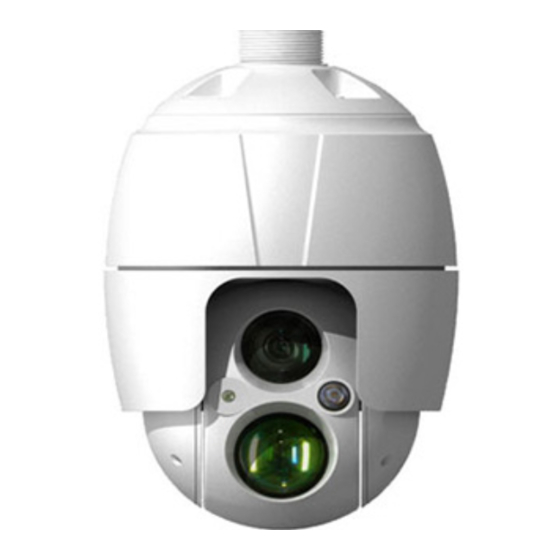
SN680D-WNIR Network
PTZ Dome
Vicon Industries Inc.
Tel: 631-952-2288 Fax: 631-951-2288 Toll Free: 800-645-9116
24-Hour Technical Support: 800-34-VICON (800-348-4266) UK: 44/(0) 1489-566300
Vicon Industries Inc. does not warrant that the functions contained in this equipment will meet your requirements or that the
operation will be entirely error free or perform precisely as described in the documentation. This system has not been designed
to be used in life-critical situations and must not be used for this purpose.
www.vicon-security.com
Document Number: 8009-8270-00-00
Issued: 714
Product specifications subject to change without notice.
Copyright © 2014 Vicon Industries Inc. All rights reserved.
Advertisement
Table of Contents

Related Manuals for Vicon SN680D-WNIR


Summary of Contents for Vicon SN680D-WNIR
- Page 1 24-Hour Technical Support: 800-34-VICON (800-348-4266) UK: 44/(0) 1489-566300 Vicon Industries Inc. does not warrant that the functions contained in this equipment will meet your requirements or that the operation will be entirely error free or perform precisely as described in the documentation. This system has not been designed to be used in life-critical situations and must not be used for this purpose.
-
Page 2: Explanation Of Graphical Symbols
WARNING TO REDUCE THE RISK OF FIRE OR ELECTRIC SHOCK, DO NOT EXPOSE THIS PRODUCT TO RAIN OR MOISTURE. DO NOT INSERT ANY METALLIC OBJECTS THROUGH THE VENTILATION GRILLS OR OTHER OPENINGS ON THE EQUIPMENT. CAUTION EXPLANATION OF GRAPHICAL SYMBOLS The lightning flash with arrowhead symbol, within an equilateral triangle, is intended to alert the user to the presence of uninsulated “dangerous voltage”... -
Page 3: Fcc Compliance Statement
FCC COMPLIANCE STATEMENT FCC INFORMATION: This equipment has been tested and found to comply with the limits for a Class A digital device, pursuant to Part 15 of the FCC Rules. These limits are designed to provide reasonable protection against harmful interference when the equipment is operated in a commercial environment. -
Page 4: Important Safety Instructions
IMPORTANT SAFETY INSTRUCTIONS Read these instructions. Keep these instructions. Heed all warnings. Follow all instructions. Do not use this apparatus near water. Clean only with dry cloth. Do not block any ventilation openings. Install in accordance with the manufacturer’s instructions. Do not install near any heat sources such as radiators, heat registers, stoves, or other apparatus (including amplifiers) that produce heat. -
Page 5: Table Of Contents
TABLE OF CONTENTS 1. Description ........................7 1.1 Components ......................... 7 1.2 Key Features......................... 8 2. Installation........................9 2.1 Installation ..........................9 2.2 Basic Configuration of Camera System ................12 2.3 Connections........................13 2.4 Network Connection & IP assignment ................14 3. - Page 6 2) Tour ..........................53 3) Motor Setup ........................54 4) RS485 ..........................55 5) View Angle........................56 6) System Menu ......................... 57 7) Privacy Zone........................58 3.5.7 System .......................... 59 1) Information ........................59 2) Security.......................... 60 3) Date & Time ........................63 4) Network..........................
-
Page 7: Description
WNIR Camera Dome. This unit should only be installed by a qualified technician using approved materials in conformance with federal, state, and local codes. Read these instructions thoroughly before beginning an installation. Always refer to Vicon’s website to assure you have the most up- to-date manual, www.vicon-security.com. -
Page 8: Key Features
1.2 Key Features Brilliant video quality The network camera offers the highly efficient H.264 video compression, which drastically reduces bandwidth and storage requirements without compromising image quality. Motion JPEG is also supported for increased flexibility. Triple Streams The network camera can deliver triple video streams simultaneously at full frame rate in all resolutions up to 1920 x 1080 using Motion JPEG and H.264. -
Page 9: Installation
2. Installation 2.1 Installation Procedure An optional mounting kit, either a wall mount (V660-HDB242) or ceiling mount (V660-HDB241), is required to install the dome camera. The wall or ceiling mount must be attached to a structural object such as hard wood or concrete that will support the weight of the mount and dome camera. - Page 10 2.1.1 Installation - Wall Mount A wall mounting plate is supplied with the wall mount; this must be attached to a structural object such as concrete that will support the weight of the mount and dome camera. 1. Select a suitable mounting location and verify there is sufficient cable to reach the middle of the wall mount.
- Page 11 2.1.2 Installation - Ceiling Mount A ceiling mounting plate is supplied with the ceiling mount; this must be attached to a structural object such as concrete that will support the weight of the mount and dome camera. 1. Select a suitable mounting location and verify there is sufficient cable to connect with cables from the housing.
-
Page 12: Basic Configuration Of Camera System
2.2 Basic Configuration of Camera System CONNECTOR COLOR DESCRIPTION DC JACK BLACK 12 VDC Ethernet, RJ-45 port RJ-45 BLACK compatible with 10/100Mbps BLACK AUDIO INPUT GRAY AUDIO OUTPUT GRAY 3P Cable ALARM INPUT BLUE ALARM OUTPUT BROWN RS485+(A) 2P Cable BROWN/WHITE RS485-(B) 1P Cable... -
Page 13: Connections
2.3 Connections Connecting the Network Connect a standard RJ-45 cable to the network port of the camera. Generally a cross-over cable is used for direct connection to a PC, while a direct cable is used for connection to a hub. ... -
Page 14: Network Connection & Ip Assignment
2.4 Network Connection & IP assignment The network camera is designed for use on an Ethernet network and requires an IP address for access. Most networks today have a DHCP server that automatically assigns IP addresses to connected devices. By the factory default, your camera is set to obtain the IP address automatically via DHCP server. -
Page 15: Operation
3. Operation The network camera can be used with Windows® operating system and browsers. The recommended browsers are Internet Explorer®, Safari®, Firefox®, Opera™ and Google® Chrome® with Windows. NOTE: To view streaming video in Microsoft Internet Explorer, set your browser to allow ActiveX controls. -
Page 16: Access From The Internet
3.2 Access from the internet Once connected, the network camera is accessible on your local network (LAN). To access the network camera from the Internet you must configure your broadband router to allow incoming data traffic to the network camera. To do this, enable the NAT traversal feature, which will attempt to automatically configure the router to allow access to the network camera. - Page 17 1) General controls Live View Page Setup Page Help Page The video drop-down list allows a customized or pre- the selection of programmed video stream on the Live View page. Stream profiles are configured under Setup > Basic Configuration > Video & Image. For more information, see “3.5.1 Basic Configuration >...
-
Page 18: Network Camera Setup
3) Video Streams The network camera provides several images and video stream formats. Your requirements and the properties of your network will determine the type you use. The Live View page in the network camera provides access to H.264 and Motion JPEG video streams, and to the list of available video streams. -
Page 19: Basic Configuration
3.5.1 Basic Configuration You can see the device information in this information page. 1) Users User access control is enabled by default. An administrator can set up other users, by giving these user names and passwords. It is also possible to allow anonymous viewer login, which means that anybody may access the Live View page, as described below:... -
Page 20: Network
“3.5.3 Video & Image” for more details. Enable WS-Security: Do not check this box to connect and monitor the network camera through Vicon’s viewing software using drivers older than 935. Note: WS-Security is an open format for signing and encryption of message parts, for supplying credentials in the form of security tokens, and for security passing those tokens in a message. -
Page 21: Video & Image
Obtain IP address via DHCP: Dynamic Host Configuration Protocol (DHCP) is a protocol that lets network administrators centrally manage and automate the assignment of IP addresses on a network. DHCP is enabled by default. Although a DHCP server is mostly used to set an IP address dynamically, it is also possible to use it to set a static, known IP address for a particular MAC address. - Page 22 Sensor Setting: - Capture mode: Use can select video frame rate at either 60/50fps or 30/25fps of resolution 1920x1080. Stream 1 Setting: - Codec: The codec settings are separated into H.264 profiles. H.264 is also known as MPEG-4 Part 10. This is the new generation compression standard for digital video. This function offers higher video resolution than Motion JPEG or MPEG-4 at the same bit rate and bandwidth, or the same quality video at a lower bit rate.
-
Page 23: Audio
- GOP size: Select the GOP (Group of Picture) size. If users want to have a high quality of fast image one by one, decrease the value. For general monitoring purposes, do not change a basic value. Such act may cause a problem to the system performance. Vicon recommends that GOP be the same as the fps. - Page 24 The network camera can transmit audio to other clients using an external microphone and can play audio received from other clients by attaching a speaker. The Setup page has an additional menu item called Audio, which allows different audio configurations, such as full duplex and simplex.
-
Page 25: Date & Time
5) Date & Time Current Server Time: This displays the current date and time (24h clock). The time can be displayed in 12h clock format (see below). New Server Time: Select your time zone from the drop-down list. If you want the server clock to automatically adjust for daylight saving time, select “Automatically adjusts for daylight saving time changes”. -
Page 26: Live View, Source
3.5.2 Live View, Source Video Input Mode: - Video Mode: Use the drop-down list to select the video input mode, NTSC or PAL. This defines the Video Output Port for the Service Monitor. When the settings are complete, click Save, or click Reset to revert to previously saved settings. -
Page 27: Video & Image
3.5.3 Video & Image 1) Basic Refer to “3.5.1 Basic Configuration > Video & Image” for details. -
Page 28: Image
2) Image Image Appearance: - Brightness: The image brightness can be adjusted in the range 1 ~ 12, where a higher value produces a brighter image. - Sharpness: Controls the amount of sharpening applied to the image. A sharper image might increase image noise especially in low light conditions. -
Page 29: Ae & Awb
Zoom Control: - Speed: The speed can be adjusted in the range 1 ~ 8. - Digital Zoom: Zoom in and out on the video image. Select On or Off. When the settings are complete, click Save, or click Reset to revert to previously saved settings. - Page 30 Auto Exposure Setting: Exposure is the amount of light detected by the camera sensor. A scene with correct exposure settings has adequate detail and contrast between white and dark values. An image with too little or too much exposure may lose detail in the scene. The camera features Auto and Manual Exposure Settings.
-
Page 31: Day & Night
4) Day & Night Day & Night Control: Select the day & night mode from among three modes. - Mode: * Automatic: Normally displays color image, and switches automatically to black & white image after the ambient light level reaches a pre-defined threshold. * Day: Always displays color image. -
Page 32: Auto Focus
* On: Activates the IR illuminator. Always displays black & white image. * Day&Night: Synchronizes the IR illuminator with Day&Night mode of the camera. Set the Day&Night mode so that the camera uses the IR illuminator at night but does not use the illuminator during the day. -
Page 33: Dis
- Mode: * Auto: Auto Focus is always active. * Manual: Auto Focus is inactive. - Focus limit: The auto focus operates from this approximate distance value. - Speed: The speed can be adjusted in the range 1 ~ 8. Note: Avoid continuous, 24-hour use of the auto focus. -
Page 34: Webcasting
7) Webcasting The network camera can stream live video to a website. Copy the HTML code generated on the screen and paste it in page code of the website you want to display live video. Note: To use webcasting service, the Enable Anonymous viewer login option must be checked. -
Page 35: Audio
3.5.4 Audio Refer to “3.5.1 Basic Configuration > Audio” for more details. -
Page 36: Event
3.5.5 Event 1) Event In On Boot This is used to trigger the event every time the network camera is started. Select “Enable on boot” to activate the motion event. Enter the Dwell time the event lasts from the point of detection, 1-180 seconds. When the settings are complete, click Save, or click Reset to revert to previously saved settings. - Page 37 Alarm In This page allows you to configure the input supported by the camera. The Port can be given as Normally Open or Normally Close state, and their Normal state can be configured. An input will be inactive as long as its Normal state equals its Current state. The 2 options for Normal state are NO (Normally Open) and NC (Normally Close).
- Page 38 Manual Trigger This option makes use of the Manual Trigger button provided on the Live View page, which is used to start or stop the event type manually. Alternatively, the event can be triggered via the product's API (Application Programming Interface). Check the Enable manual trigger box to activate the manual trigger (up to 4 manual triggers).
- Page 39 Motion Motion detection is used to generate an alarm whenever movement occurs (or stops) in the video image. A total of 8 Motion and/or Mask windows can be created and configured. Motion is detected in defined Motion windows, which are placed in the video image to target specific areas.
- Page 40 To exclude parts of the Include window, select the New Mask at the mouse menu and position the Mask window as required. Motion Detection Setting: The behavior for each window is defined by adjusting the Threshold and Sensitivity, as described below. The combination of these parameters defines whether motion has occurred;...
- Page 41 Network Loss This is used to trigger the event every time the network connection fails. Select “Enable network loss” to activate the Network Loss event. Select a dwell time for how long the event will last from the point of detection. When the settings are complete, click Save, or click Reset to revert to previously saved settings.
-
Page 42: Event Out
This is used to trigger the event when camera tampering occurs. Select “Enable tampering” to activate the Tempering event. Enter a dwell time from 1-180 seconds for how long this event will last. Click the Save button to save the settings, or click the Reset button to clear all of the information you entered without saving it. - Page 43 - Mail Server/Port: Enter the host names (or IP addresses) and port numbers for your mail server in the fields provided to enable the sending of notifications and image email messages from the network camera to predefined addresses via SMTP. - Connection Security: Select None, SSL or StartTLS from the drop-down list as required.
- Page 44 When the network camera detects an event, it can record and save images to an FTP server. Images can be sent as e-mail attachments. Check the “Enable FTP” box to enable the service. FTP Setting: - Server: Enter the server's IP address or host name. NOTE: A DNS server must be specified in the TCP/IP network settings if using a host name.
- Page 45 HTTP Server When the network camera detects an event, the HTTP Server is used to receive uploaded image files and/or notification messages. Check the “Enable HTTP server”box to enable the service. HTTP Server Setting: - Name: The name of the HTTP event server. Use a descriptive name. - URL: The network address to the server and the script that will handle the request.
- Page 46 Alarm Out When the network camera detects an event, it can control external equipment to its alarm output port. Enable alarm out: Click the “Enable alarm out” box to enable the Alarm Out port. - Type: Select a type, NO (Normally Open) or NC (Normally Closed). The default setting is NO.
- Page 47 Audio Alert When the network camera detects an event, it can output predefined audio data to an external speaker. Check the “Enable audio alert” box to enable the service. Audio Alert Setting: To use the Audio Alert with the network camera, an audio data file made by the user must be uploaded from your PC.
- Page 48 PTZ Preset When the camera detects an event, you can move the camera to a predefined preset position. Check the “Enable PTZ preset” box to enable the service and return to the Home position once the event has ended. Click the Save button to save the settings, or click the Reset button to clear all of the information you entered without saving it.
- Page 49 Event Notification When the network camera detects an event, Notification server is used to receive notification messages as a type of XML data format. Check the “Enable event notification” box to enable the service. Event Notification Setting: - Notification Server URL/port: Enter the network server URL and the port that will handle the request.
-
Page 50: Event Map
3) Event Map The event map allows you to change the settings and establish a schedule for each event trigger from the network camera; up to max. 15 events can be registered. Click the Add button to make a new event map; a popup window display as below. To change an existing event, select that event and click the Modifiy button;... - Page 51 • General: Enter the name for a new event map. • Event In: Select an event type in the drop-down list. • Event Out: - E-mail: Check box to allow email notification. Select the email addresses you want to notify via email that an event has occurred. - FTP: Select checkbox beside FTP to record and save images to an FTP server when an event has occurred.
-
Page 52: Dome Configuration
3.5.6 Dome Configuration 1) Preset If specific places are viewed routinely, you should program Presets. A Preset is a programmed video scene with automatic pan, tilt, zoom and focus settings. Once programmed, clicking the Preset number or clicking the Go button in the PTZ Control Panel calls up that Preset automatically. -
Page 53: Tour
4. Repeat step 2 through 3 for each additional Preset position. 2) Tour There are 8 programmable Tours. Each Tour consists of up to 100 Presets. • Tour Setting: - Tour Number: The Tour number can be selected in the range 1 - 8. - Title: Up to 12 characters (alphanumeric characters and space) - Repeat: Select number of repetitions from Continuous to 90. -
Page 54: Motor Setup
• Tour Position Setup: - Tour position: The Tour position can be selected in the range 1 ~ 100. - Preset number: Show the selected Preset number for the Tour position. - Dwell Time: Select the Dwell Time from 0 to 99 seconds that the tour will stay at this position. -
Page 55: Rs485
4) RS485 • RS485 Setting: - DOME ID: Enter identification number for external PTZ device. The DOME ID can be adjusted in the range 1 ~ 3999. - Protocol: Select the PTZ protocol to communicate with external PTZ device. Auto or Pelco P/D. -
Page 56: View Angle
5) View Angle • View Angle Setting: - Tilt angle limit: This option is designed to limit the tilt angle if there is some obstruction when zooming out on specific areas of the tilt angle. - Flip: * Off: The dome camera moves up to 90 vertically. * Auto: When the camera reaches the floor directly above the moving object, it will stop. -
Page 57: System Menu
6) System Menu • Dome Information: Provides essential information about the dome if service is required. This information cannot be modified. • System Menu setting: - Dome Answer: Select On or Off for acknowledge command from the dome. This option is helpful to escape the conflict of the command using some DVRs. -
Page 58: Privacy Zone
7) Privacy Zone Using privacy zones (masks), up to 8 unwanted scenes in a camera be can hidden. The color of privacy zone mask is gray. • Privacy Zone Setting: Follow the steps below to configure the privacy zones: 1. Aim the camera (view direction and lens control) using the Arrow and Zoom button in PTZ Control Panel. -
Page 59: System
3.5.7 System 1) Information System information can be entered on this page. This page is very useful when device information is required after installation. • Device Name Configuration: Enter the device name. • Location Configuration: Enter the location information. Up to four locations can be entered. Click the Save button to save the settings, or click the Reset button to clear all of the information you entered without saving it. -
Page 60: Security
• WS-Security Setting: Do not check this box to connect and monitor the network camera through Vicon’s viewing software using drivers older than 935. Note: WS-Security is an open format for signing and encryption of message parts, for supplying credentials in the form of security tokens, and for security passing those tokens in a message. - Page 61 Click the Save button to save the settings, or click the Reset button to clear all of the information you entered without saving it. HTTPS For greater security, the network camera can be configured to use HTTPS [Hypertext Transfer Protocol over SSL (Secure Socket Layer)], so that all communication that would otherwise go via HTTP will instead go via an encrypted HTTPS connection.
- Page 62 IP Filtering Checking the “Enable IP address filtering” box enables the IP address filtering function. Up to 256 IP address entries may be specified (a single entry can contain multiple IP addresses). Click the Add button to add new filtered addresses. When the IP address filter is enabled, addresses added to the list are set as allowed or denied addresses.
-
Page 63: Date & Time
3) Date & Time • Current Server Time: This displays the current date and time (24h clock). The time can be displayed in 12h clock format (see below). • New Server Time: Select your time zone from the drop-down list. If you want the server clock to automatically adjust for daylight saving time, select ““Automatically adjusts for daylight saving time changes”. -
Page 64: Network
4) Network Settings regarding the network can be configured. Settings for IP, DNS, Host Name, Services Port, and ARP/Ping can be established, along with settings for DDNS, RTP, uPnP, QoS, NAT, Zeroconfig and Bonjour. - Page 65 Basic • IP Address Configuration: - Obtain IP address via DHCP: Dynamic Host Configuration Protocol (DHCP) is a protocol that lets network administrators centrally manage and automate the assignment of IP addresses on a network. DHCP is enabled by default. Although a DHCP server is mostly used to set an IP address dynamically, it is also possible to use it to set a static, known IP address for a particular MAC address.
- Page 66 DDNS • Internet DDNS (Dynamic Domain Name Service): When using the high-speed Internet with the telephone or cable network, users can operate the network camera even on the floating IP environment in which IPs are changed at every access. Note: At least a primary DNS server must be configured in DNS configuration settings to use Dynamic DNS.
- Page 67 RTP Users can configure settings for sending and receiving audio or video on a real-time basis. These settings are the IP address, port number, and Time-To-Live value to use for the media stream(s) in multicast H.264 format. Only certain IP addresses and port numbers should be used for multicast streams.
- Page 68 - RTP port: Enter a value between 1024 and 65530. - RTP TTL: Enter a value between 1 and 255. If the network status is smooth, enter a lower value. However, if the network status is poor, enter a higher value. When there are many network cameras or users, a higher value may cause a heavy load to the network.
- Page 69 UPnP The network camera includes support for UPnP™. UPnP is enabled by default, and the network camera is then automatically detected by operating systems and clients that support this protocol. Enter a name in the Friendly name field. Note: UPnP must be installed on your workstation if running Windows XP. To do this, open the Control Panel from the Start Menu and select Add/Remove Programs.
- Page 70 • DSCP Settings: For each type of network traffic supported by your network video product, enter a DSCP (Differentiated Services Code Point) value. This value is used to mark the traffic’s IP header. When the marked traffic reaches a network router or switch, the DSCP value in the IP header tells the router or switch which type of treatment to apply to this type of traffic, for example, how much bandwidth to reserve for it.
- Page 71 NAT A broadband router allows devices on a private network (LAN) to share a single connection to the Internet. This is done by forwarding network traffic from the private network to the “outside,” that is, the Internet. Security on the private network (LAN) is increased since most broadband routers are pre-configured to stop attempts to access the private network (LAN) from the public network/Internet.
- Page 72 Click the Save button to save the settings, or click the Reset button to clear all of the information you entered without saving it. Zeroconfig Zeroconfig allows the network camera to create and assign the IP address for network cameras and connect to a network automatically.
- Page 73 Bonjour The network camera includes support for Bonjour. When enabled, the network camera is automatically detected by operating systems and clients that support this protocol. Note: Bonjour - Also known as zero-configuration networking, Bonjour enables devices to automatically discover each other on a network, without having to enter IP addresses or configure DNS servers.
-
Page 74: Language
5) Language Select the desired language setting. Currently 4 languages are supported, English, Korean, Russian and Chinese. Click the Save button to save the settings, or click the Reset button to clear all of the information you entered without saving it. -
Page 75: Maintenance
6) Maintenance • Maintenance: - Restart: The unit is restarted without changing any of the settings. Use this method if the unit is not behaving as expected. - Reset: The unit is restarted and most current settings are reset to factory default values. The settings that are not affected are: * the boot protocol (DHCP or static) * the static IP address... -
Page 76: Support
Note: Backup and Restore can only be used on the same unit running the same firmware. This feature is not intended for multi-configurations or for firmware upgrades. 7) Support The support page provides valuable information when troubleshooting a problem or when contacting the technical assistants. - Page 77 - Media Check: Click the Media Check button to get the information about the camera’s video and audio stream. The pop-up window displays as below. - Networks Check: Click the Network Check button to get the information about the camera’s network setting and traffic. The pop-up window displays as below.
- Page 78 - Hardware Check: Click the Hardware Check button to diagnose the camera’s hardware, such as video displaying and speaker and microphones functioning.
-
Page 79: About
3.5.8 About This page shows Vicon Industries company information including website. -
Page 80: Help
3.6 Help The Help information window is provided as a popup window so that users can open and read it without a need for log-in. It offers descriptions of settings and a Help page, so users can manipulate the network camera without having to reference the manual. -
Page 81: Resetting To The Factory Default Settings
3.7 Resetting to the Factory Default Settings To reset the network camera to the original factory settings, go to the Setup > System > Maintenance web page (described in “3.5.7 System > Maintenance” of User’s Manual) or use the Reset button on the network camera, as described below: ... -
Page 82: Appendix
4. Appendix 4.1 Troubleshooting When troubleshooting if problems occur, verify the installation of the network camera with the instructions in this manual and with other operating equipment. Isolate the problem to the specific piece of equipment in the system and refer to the equipment manual for further information. Problems/Symptoms Possible Causes or Corrective Actions The camera cannot be... -
Page 83: Alarm Connection
4.2 Alarm Connection The following connection diagram gives an example of how to connect a network camera. 4.3 Preventive Maintenance Preventive maintenance allows detection and correction of minor that faults before they become serious and cause equipment failure. Every three-month, perform the following maintenance. 1. -
Page 84: Product Specification
4.4 Product Specification SN680D-WNIR PTZ DOME NETWORK CAMERA Feature Specification IMAGE Image Sensor 1/2.8” SONY Exmor CMOS 4.3mm ~ 129.0mm Lens 30x A/F Optical Zoom, 16x Digital Zoom Scanning Mode Progressive Scan Min. Illumination Color: 0.5Lux, B/W: 0.1Lux AE/AWB D&N True D&N (IR-cut filter) - Page 85 NETWORK Max. Connections IPv4/IPv6, Manual, TCP/IP, UDP, HTTP, RTP, RTSP, Protocols NTP, DHCP, SMTP, DDNS, HTTPS, RTCP, FTP, Bonjour NAS Support JPEG push DDNS Remote Client Web browser, SmartManager Installation Tool SmartManager MISCELLANEOUS Weatherproof IP66 Power 12VDC ± 10% Power Consumption 3.0 A (36 W) Operating Temperature -22F to 122F (-30C ~ 50C)
-
Page 86: System Requirement For Web Browser
4.5 System Requirement for Web Browser Operating System: Microsoft® Windows® OS Series CPU: Intel® Core™ 2 Duo 2GHz or higher, 1GB RAM or more, 10GB free disk or higher VGA: AGP, Video RAM 32MB or higher (1024x768, 24bpp or higher) 4.6 General Performance Considerations When setting up your system, it is important to consider how various settings and situations will affect performance. -
Page 87: Shipping Instructions
Use the following procedure when returning a unit to the factory: 1. Call or write Vicon f or a Return A uthorization ( R.A.) at one of t he locations listed be low. Record the name of the Vicon employee who issued the R.A. -
Page 88: Vicon Standard Equipment Warranty
“autopan” or “tour” modes of operation. Such continuous operation is outside the scope of this warranty. Any product sold as “special” or not listed in Vicon’s commercial price list: One year from date of original retail purchase. - Page 89 Vicon Industries Inc. Internet Address: www.vicon-security.com SN-680D-WNIR Network PTZ Dome...
Need help?
Do you have a question about the SN680D-WNIR and is the answer not in the manual?
Questions and answers