Sign In
Upload
Manuals
Brands
adept technology Manuals
Robotics
Cobra s350
adept technology Cobra s350 Manuals
Manuals and User Guides for adept technology Cobra s350. We have
1
adept technology Cobra s350 manual available for free PDF download: User Manual
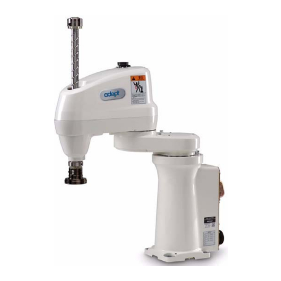
adept technology Cobra s350 User Manual (104 pages)
Robot
Brand:
adept technology
| Category:
Robotics
| Size: 3.08 MB
Table of Contents
Table of Contents
5
Introduction
11
Product Description
11
Adept Cobra S350 Robots
11
Figure 1-1. Adept Cobra S350 Robot
11
Adept Motionblox-40R Distributed Servo Controller
12
Figure 1-2. Robot Joint Motions
12
Adept Smartcontroller CX
13
Figure 1-3. Motionblox-40R (MB-40R)
13
Figure 1-4. Adept Smartcontroller CX
13
Installation Overview
14
How Can I Get Help
15
Related Manuals
15
Adept Document Library
15
Safety
17
Warnings, Cautions, and Notes in Manual
17
Warning Labels on the Robot
18
Precautions and Required Safeguards
18
Safety Barriers
18
Figure 2-1. Safety Warning Label on Adept Cobra S350
18
Impact and Trapping Points
19
Additional Safety Information
20
Risk Assessment
21
Exposure
21
Severity of Injury
21
Avoidance
22
CAT-1 Control System
22
Intended Use of the Robots
23
Robot Modifications
24
Acceptable Modifications
24
Unacceptable Modifications
24
Transport
25
Safety Requirements for Additional Equipment
25
Sound Emissions
25
2.10 Thermal Hazard
26
2.11 Working Areas
26
2.12 Qualification of Personnel
26
2.13 Safety Equipment for Operators
27
2.14 Protection against Unauthorized Operation
27
2.15 Safety Aspects While Performing Maintenance
27
2.16 Risks Due to Incorrect Installation or Operation
28
2.17 What to Do in an Emergency Situation
28
Robot Installation
29
Transport and Storage
29
Figure 3-1. Transporting Robot
29
Unpacking and Inspecting the Adept Equipment
30
Before Unpacking
30
Upon Unpacking
30
Repacking for Relocation
30
Environmental and Facility Requirements
31
Mounting the Robot
31
Mounting Surface
31
Robot Mounting Procedure
32
Figure 3-2. Mounting Hole Pattern for Robot
32
Figure 3-3. Rotate J2 Axis to Safe Position
33
Motionblox-40R
35
Introduction to the Motionblox-40R
35
Figure 4-1. Adept MB-40R Front View
35
Description of Connectors on MB-40R Interface Panel
36
Figure 4-2. MB-40R Interface Panel
36
MB-40R Operation
37
Status LED on MB-40R
37
Figure 4-3. Controls and Indicators on MB-40R
37
Status Panel
38
Brake Release Button on MB-40R
38
Brake Release Connector
39
Connecting Digital I/O to the System
40
Figure 4-4. Connecting Digital I/O to the System
41
Using Digital I/O on MB-40R XIO Connector
43
Optional I/O Products
44
XIO Input Signals
44
XIO Input Specifications
44
Typical Input Wiring Example
45
Figure 4-5. Typical User Wiring for XIO Input Signals
45
XIO Output Signals
46
XIO Output Specifications
46
Typical Output Wiring Example
47
XIO Breakout Cable
47
Figure 4-6. Typical User Wiring for XIO Output Signals
47
Figure 4-7. Optional XIO Breakout Cable
47
MB-40R Dimensions
49
Figure 4-8. MB-40R Mounting Dimensions
49
System Installation
51
System Cable Diagram
51
Figure 5-1. System Cable Diagram for Adept Cobra S350 Robots
51
Cables and Parts List
52
Installing the Smartcontroller
52
Cable Connections from MB-40R to Smartcontroller
53
Cable Connections from MB-40R to Robot
53
Installing the Arm Power/Signal Cable
53
Connecting 24 VDC Power to MB-40R Servo Controller
54
Specifications for 24 VDC Power
54
Details for 24 VDC Mating Connector
55
Procedure for Creating 24 VDC Cable
55
Installing the 24 VDC Cable
56
Figure 5-2. User-Supplied 24 VDC Cable
56
Connecting 200-240 VAC Power to MB-40R
57
Specifications for AC Power
57
Facility Overvoltage Protection
57
AC Power Diagrams
58
Figure 5-3. Typical AC Power Installation with Single-Phase Supply
58
Figure 5-4. Single-Phase AC Power Installation from a Three-Phase AC Supply
58
Details for AC Mating Connector
59
Procedure for Creating 200-240 VAC Cable
59
Installing AC Power Cable to MB-40R
60
Grounding the Adept Robot System
60
Ground Point on Robot Base
60
Figure 5-5. AC Power Mating Connector
60
Figure 5-6. Ground Point on Robot Base
60
Ground Point on Motionblox-40R
61
Robot-Mounted Equipment Grounding
61
Installing User-Supplied Safety Equipment
61
Figure 5-7. User Ground Location on MB-40R
61
System Operation
63
Using the Brake Release Button
63
Brakes
63
Brake Release Button on Robot
63
Figure 6-1. Brake Release Button for Third and Fourth Axes
63
System Start-Up Procedure
64
Figure 6-2. Typical Start-Up Screen
64
Learning to Program the Robot
65
Optional Equipment Installation
67
Installing End-Effectors
67
Removing and Reinstalling the User Flange
67
Removing the Flange
67
Reinstalling the Flange
68
Figure 7-1. User Flange Removal Details
68
User Connections on Robot
69
User Air Lines
69
Figure 7-2. User Air and Electrical Connectors on Robot
69
User Electrical Lines
70
Optional Solenoid Cable
70
Mounting Options for User Connections
71
Routing User Connections through the Z-Axis Shaft
71
Figure 7-3. Mechanical End Bolts and Stoppers on Robot
71
Attaching Stays to Support User Connections
72
Figure 7-4. Stay Attached to Robot's Exterior
72
Figure 7-5. Dimensions for Fabricating User-Supplied Stay
73
Camera Mounting
74
Figure 7-6. Camera Mounting Details
74
Camera Bracket Drawings
75
Figure 7-7. Camera Bracket Drawing, Page 1 of 2
75
Figure 7-8. Camera Bracket Drawing, Page 2 of 2
76
Maintenance
77
Periodic Maintenance Schedule
77
Checking of Safety Systems
78
Checking Robot Mounting Bolts
78
Lubricate Joint 3 Ball Screw
78
Required Grease for the Robot
78
Lubrication Procedure
79
Figure 8-1. Lubrication of Joint 3 Quill
79
Replacing Encoder Battery
80
Figure 8-2. Removing Battery Cover
80
Figure 8-3. Removing First Old Battery
81
Figure 8-4. Installing First New Battery
81
Figure 8-5. Removing Second Old Battery
82
Figure 8-6. Installing Second New Battery
82
Inspecting Timing Belts
83
Technical Specifications
85
Dimension Drawings
85
Figure 9-1. Adept Cobra S350 Top and Side Dimensions
85
Figure 9-2. Adept Cobra S350 Robot Working Envelope
86
Figure 9-3. Tool Flange Dimensions for Adept Cobra S350 Robots
87
Robot Specifications
88
Cleanroom Robots
91
10.1 Cobra S350 CR/ESD Cleanroom Option
91
Introduction
91
Figure 10-1. Adept Cobra S350 CR/ESD Cleanroom Robot
91
Specifications
92
10.2 Connections
92
Figure 10-2. Cleanroom Connections
92
10.3 Requirements
93
10.4 ESD Control Features
93
10.5 Maintenance
94
Bellows Replacement
94
Procedure for Lower Bellows Replacement
94
Figure 10-3. Cleanroom Lower Bellows Replacement
94
Procedure for Upper Bellows Replacement
95
Lubrication
95
Figure 10-4. Cleanroom Upper Bellows Replacement
95
10.6 Dimension Drawings
96
Figure 10-5. Adept Cobra S350 CR/ESD Top and Side Dimensions
96
Figure 10-6. Adept Cobra S350 CR/ESD Robot Working Envelope
97
Index
99
Advertisement
Advertisement
Related Products
adept technology AdeptViper s650
adept technology AdeptViper s850
adept technology Cobra s800
adept technology Quattro s650H
adept technology Quattro s650HS
adept technology Quattro s800H
adept technology Quattro s800HS
adept technology Cobra s600
adept technology Cobra Dual
adept technology SmartController EX
adept technology Categories
Robotics
Controller
Network Router
Thermostat
Control Unit
More adept technology Manuals
Login
Sign In
OR
Sign in with Facebook
Sign in with Google
Upload manual
Upload from disk
Upload from URL