
Subscribe to Our Youtube Channel
Related Manuals for Redback ST10000


Summary of Contents for Redback ST10000
- Page 1 Owner’s Guide Redback Smart 3-Phase Hybrid System ST10000 Inverter and BE14000-HV Battery Enclosures v1.6...
- Page 2 Privacy notice Redback will use the personal information provided to us only for warranty purposes. Without this information we will not be able to process your warranty claim. If you require further information about our privacy policy, please visit our website at redbacktech.com.
-
Page 3: Table Of Contents
Auto mode ............................19 Standby mode ............................. 19 Charge battery mode .......................... 19 Discharge battery mode ........................20 Backup mode ............................20 Onboarding the inverter ........................21 Ethernet .............................. 21 Owner’s Guide – Redback ST10000 and BE14 000-HV - v1.6... - Page 4 Inverter Status Icons ........................... 24 SM3000 Smart Meter diagnostics ....................... 25 Maintenance ............................26 Schedule ............................. 26 Cleaning the BE14000-HV fan filters ....................27 Specifications ............................28 Redback installation details ........................31 Owner’s Guide – Redback ST10000 and BE14000-HV – v1.6...
-
Page 5: Welcome
You can then access the system using the Redback app or portal, see how the system is working for you, and gain insights to help maximise your consumption of self-generated energy. - Page 6 Handle all parts with care and follow instructions provided. WARNING: Fire hazard Do not keep combustible or flammable materials in the same room as the equipment. The Redback Smart 3- phase Hybrid Inverter and or Battery Enclosures contain relays and switches that are not ignition protected.
-
Page 7: Features And Benefits Of Your Redback System
Charge (SoC) to extend battery life. Critical setting protection Critical system settings may only be changed by electrically qualified personnel. Solar array ground fault and Electrical safety for all parts of your system. insulation monitoring Owner’s Guide – Redback ST10000 and BE14 000-HV - v1.6... -
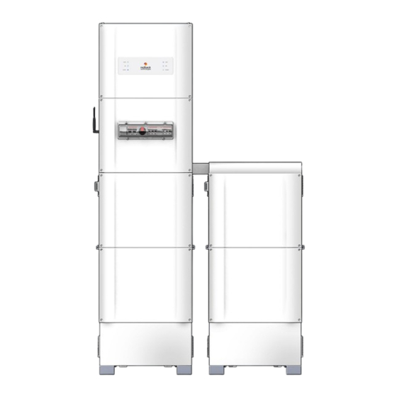
Page 8: Know Your Product
PV Array DC isolator Enclosure air inlet (Filter cover) Backup circuit AC isolator (3, bridged) Enclosure padlock hoop Bypass switch (3, bridged) Enclosure isolator Inverter AC isolator (3, bridged) BoS front cover Thumbwheel Owner’s Guide – Redback ST10000 and BE14000-HV – v1.6... -
Page 9: Status Panel Leds
Redback Technolo gies Status Panel LEDS BoS switchgear Owner’s Guide – Redback ST10000 and BE14 000-HV - v1.6... -
Page 10: Batteries
Introductio n Batteries Your Redback system has a storage capacity of up to 28kWh using 4 or 8 Capacity (kWh) Pylontech lithium-ion batteries and one or two BE14000-HV Battery H48050 H48074 Enclosures. Batteries are serial connected, and all batteries must be in @2.4kWh... -
Page 11: Backup Circuit (Optional)
Backup circuit (optional) Your Redback inverter can directly control and power a backup circuit. This feature is used to extend the run time of a small number of low power or occasional use devices that you have prioritised for use during a power outage. -
Page 12: Getting The Best From Your System
Getting the best from your system Getting the best from your system Your Redback system is designed to operate autonomously – the level of interaction is up to you. A set-and-forget approach will work fine: occasional maintenance is all that is required. -
Page 13: Monitor Performance
Redback Technolo gies Monitor performance Redback offers two choices for monitoring the energy performance of your household. 7.2.1 MYREDBACK APP MYRedback provides a simple, up-to-date view of what’s happening at your place – it’s great for quickly checking the energy flow at home. MYRedback is available for Android 7 or higher and iOS 12.1 or higher. -
Page 14: Getting The Best From Your Batteries
To use this feature, ask your electrician to install a dedicated, relay-controlled circuit for the equipment. The schedules are created in the Redback portal, under the CONTROL tab. Multiple daily events are permitted excepting that they may not overlap and must start and finish on the same day. Manual control is also possible, using the ON and OFF controls. -
Page 15: Getting The Best From Your Backup Circuit
Hot water systems Mobile phone or small-device chargers Spas, saunas, pool pumps Household tank water pumps Battery chargers & corded Power tools Low-energy LED or CCFL lighting Incandescent or high-power lighting Owner’s Guide – Redback ST10000 and BE14 000-HV - v1.6... -
Page 16: Inverter Operation
Inverter operation Inverter operation Your Redback inverter has sophisticated software controls available in the Redback app or portal, however there are some physical controls or functions at the unit. Locking up the batteries Secure the Battery Enclosures to: Prevent unauthorised access to the batteries. -
Page 17: Shutdown Procedure
Occasionally, it may be necessary to shut down the inverter interrupting all inverter functions, noting that PV, battery, and grid supplies remain energised to the isolators. Follow the procedure below to shut down your system. Owner’s Guide – Redback ST10000 and BE14 000-HV - v1.6... -
Page 18: Start Procedure
Inverter operation Start procedure Start your inverter as shown below. Owner’s Guide – Redback ST10000 and BE14000-HV – v1.6... -
Page 19: Inverter Operating Modes
Redback Technolo gies Inverter operating modes The inverter operating modes are summarised below. Select modes using the Redback app or portal. Auto mode AUTO is the default operating mode, maximising consumption of self-generated and stored energy. If the inverter mode has been changed, AUTO can be reselected from the Redback app or portal. -
Page 20: Discharge Battery Mode
Backup Load the inverter will consider this an overload and will automatically shut down. The inverter will restart after approximately one minute. If overload persists, the cycle will repeat. Owner’s Guide – Redback ST10000 and BE14000-HV – v1.6... -
Page 21: Onboarding The Inverter
Onboarding connects your inverter to the internet using your network. If you This equipment is not compatible can login to the Redback portal and your system is “Online”, then your system with 5Ghz Wi-Fi networks or is onboarded. Connection to the network is by Ethernet cable or Wi-Fi. -
Page 22: Troubleshooting
Contact your installer for assistance. Note: The Solar Supply Main Switch is Solar Supply Main There is a wiring or Switch trips inverter fault. usually located on the main switchboard. Owner’s Guide – Redback ST10000 and BE14000-HV – v1.6... -
Page 23: Inverter Unexpected Shutdown
Fi extender; connect using ethernet. router’s antenna. Attempting connection to a 5Ghz Wi-Fi network This equipment is not compatible with 5Ghz Wi-Fi networks. Use a 2.4Ghz network or ethernet. Owner’s Guide – Redback ST10000 and BE14 000-HV - v1.6... -
Page 24: Inverter Status Icons
Troubleshooting Inverter Status Icons Your Redback inverter is equipped with an icon array to indicate system status and aid diagnosis. The table below lists indications, probable cause, and rectification steps you can try yourself. Refer to page 9 to identify controls. -
Page 25: Sm3000 Smart Meter Diagnostics
SM3000 Smart Meter diagnostics The Redback SM3000 Smart Meter is usually located at the main switchboard. It detects the grid energy traffic of all 3 phases and indicates if the site overall is importing or exporting energy to the grid. This information informs inverter operation. -
Page 26: Maintenance
WARNING: ELECTROCUTION HAZARD. Lethal voltages may be present. There are no user serviceable parts inside. Do not remove front covers. Your Redback system is a low maintenance product. You should undertake the minor annual maintenance identified below. Internal maintenance must be conducted by a qualified person, such as your installer. -
Page 27: Cleaning The Be14000-Hv Fan Filters
Refit the filter covers, ensuring the vents face downward. There should be two tactile “clicks” as the snap-fits engage. Switch the Battery Enclosure Isolators OFF (left) Switch the BATTERY SYSTEM DC isolator ON (up). Owner’s Guide – Redback ST10000 and BE14 000-HV - v1.6... -
Page 28: Specifications
Max. Power (charge) DC 10000W Max. Current (discharge) DC 25 A Max. Power (charge) DC 10000W Battery Type Li-ion Battery Depth of Discharge Short Circuit Current 400A Decisive Voltage Class (DVC) DVC-C Owner’s Guide – Redback ST10000 and BE14000-HV – v1.6... - Page 29 Ingress Protection Rating IP54 Dimensions (W x D x H mm) 545 x 348 x 1125 Material Steel cabinet; Aluminium front covers; Stainless steel fittings Finish Powdercoat and internal sealants Owner’s Guide – Redback ST10000 and BE14 000-HV - v1.6...
- Page 30 IEC 62109-1:2010 IEC 62040-1:2017 EN 61000 CE Mark (LVD, EMC, RoHS directives) IEC62109-2:2011 IEC 62477-1:2012 DESIGNED WITH INSTALLATION STANDARDS CONSIDERED AS/NZS 3000:2018 AS/NZS 5139:2019 AS/NZS 5033:2014 (inc. Amd 1 & 2) Owner’s Guide – Redback ST10000 and BE14000-HV – v1.6...
-
Page 31: Redback Installation Details
☐ ☐ Battery 7 ☐ ☐ Battery 8 ☐ ☐ Backup circuits ☐ ☐ ☐ ☐ ☐ ☐ Relay 1 ☐ ☐ Relay 2 ☐ ☐ Relay 3 ☐ ☐ Owner’s Guide – Redback ST10000 and BE14 000-HV - v1.6... - Page 32 Notes redbacktech.com Owner’s Guide – Redback ST10000 and BE14000-HV – v1.6...
Need help?
Do you have a question about the ST10000 and is the answer not in the manual?
Questions and answers