Table of Contents
Advertisement
Quick Links
POWERFLUX 5000
POWERFLUX 5000
POWERFLUX 5000
POWERFLUX 5000
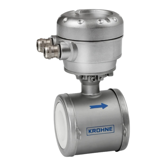
Electromagnetic flowmeter in sandwich version
The documentation is only complete when used in combination with the relevant
documentation for the signal converter.
© KROHNE 01/2017 - 4005807401- QS POWERFLUX 5000 SW- R01 en
Quick Start
Quick Start
Quick Start
Quick Start
Advertisement
Table of Contents

Subscribe to Our Youtube Channel
Related Manuals for KROHNE POWERFLUX 5000


Summary of Contents for KROHNE POWERFLUX 5000
- Page 1 Quick Start Quick Start Quick Start Quick Start Electromagnetic flowmeter in sandwich version The documentation is only complete when used in combination with the relevant documentation for the signal converter. © KROHNE 01/2017 - 4005807401- QS POWERFLUX 5000 SW- R01 en...
-
Page 2: Table Of Contents
3 Electrical connections 3.1 Safety instructions......................15 3.2 Grounding ........................15 3.3 Virtual reference for IFC 300 (W and F version) ............16 4 Technical data 4.1 Dimensions and weights ....................17 www.krohne.com 01/2017 - 4005807401- QS POWERFLUX 5000 SW- R01 en... -
Page 3: Safety Instructions
If you need to return the device to the manufacturer or supplier, please fill out the form • contained on the CD-ROM and send it with the device. Unfortunately, the manufacturer cannot repair or inspect the device without the completed form. 01/2017 - 4005807401- QS POWERFLUX 5000 SW- R01 en www.krohne.com... -
Page 4: Installation
6 Signal cable (depends on version) INFORMATION! Assembly materials and tools are not part of the delivery. Use the assembly materials and tools in compliance with the applicable occupational health and safety directives. www.krohne.com 01/2017 - 4005807401- QS POWERFLUX 5000 SW- R01 en... -
Page 5: Device Description
Product specific information and extensive product specification is available using PICK, the Product Information Center KROHNE web-tool. PICK can be found via the service menu button on the KROHNE.com website. The POWERFLUX is available in different sizes and constructions; Options: •... -
Page 6: Nameplate Measuring Sensor (Example)
1 Name and address of the manufacture 2 Type designation and CE sign with number of notified body 3 Calibration / GK / Size and protection class data 4 PED data www.krohne.com 01/2017 - 4005807401- QS POWERFLUX 5000 SW- R01 en... -
Page 7: Storage
• Allen key (4 mm) • Small screwdriver • Wrench for cable glands • Wrench for wall mounting bracket (remote version only) • Torque wrench for installing flowmeter in pipeline 01/2017 - 4005807401- QS POWERFLUX 5000 SW- R01 en www.krohne.com... -
Page 8: General Requirements
Do not expose the signal converter to intense vibration. The flowmeters are tested for a • vibration level in accordance with IEC 68-2-64. 2.8.1 Vibration Figure 2-6: Avoid vibrations 2.8.2 Magnetic field Figure 2-7: Avoid magnetic fields www.krohne.com 01/2017 - 4005807401- QS POWERFLUX 5000 SW- R01 en... -
Page 9: Installation Conditions
Inlet length: using bends in 2 dimensions: ≥ 5 DN; when having bends in 3 dimensions: ≥ 10 DN INFORMATION! 2 Dimensional bends in a vertical plane only, while 3 Dimensional bends both occur in a vertical and horizontale plane. 01/2017 - 4005807401- QS POWERFLUX 5000 SW- R01 en www.krohne.com... -
Page 10: T-Section
INSTALLATION POWERFLUX 5000 2.9.3 T-section Figure 2-10: Distance behind a T-section 1 ≥ 10 DN 2.9.4 Bends CAUTION! Avoid draining or partial filling of the flow sensor www.krohne.com 01/2017 - 4005807401- QS POWERFLUX 5000 SW- R01 en... -
Page 11: Open Feed Or Discharge
2.11 Flange deviation CAUTION! Max. permissible deviation of pipe flange faces: ≤ 0.5 mm / 0.02" Figure 2-12: Flange deviation 2.12 Control valve Figure 2-13: Installation in front of a control valve 01/2017 - 4005807401- QS POWERFLUX 5000 SW- R01 en www.krohne.com... -
Page 12: Pump
1 Inlet: ≥ 3 DN 2.14 Air venting and vacuum forces Figure 2-15: Air venting 1 ≥ 5 m 2 Air ventilation point Figure 2-16: Vacuum 1 ≥ 5 m www.krohne.com 01/2017 - 4005807401- QS POWERFLUX 5000 SW- R01 en... -
Page 13: Mounting Position
1/10...4" 150 lb 1/10...3" 300 lb CAUTION! Pressures at 20 C / 68 • ° ° For higher temperatures, the pressure and temperature ratings are as per ASME B16.5. • 01/2017 - 4005807401- QS POWERFLUX 5000 SW- R01 en www.krohne.com... - Page 14 The specified torque values are dependent on variables (temperature, bolt material, gasket material, lubricants, etc.) which are not within the control of the manufacturer. Therefore the values should be regarded as indicative only. www.krohne.com 01/2017 - 4005807401- QS POWERFLUX 5000 SW- R01 en...
-
Page 15: Electrical Connections
The device must be grounded in accordance with regulations in order to protect personnel against electric shocks. Figure 3-1: Grounding 1 Metal pipelines, not internally coated. Grounding without grounding rings! 2 Metal pipelines with internal coating and non-conductive pipelines. Grounding with grounding rings! 01/2017 - 4005807401- QS POWERFLUX 5000 SW- R01 en www.krohne.com... -
Page 16: Virtual Reference For Ifc 300 (W And F Version)
• Electrical conductivity: ≥ 200 µS/cm • Signal cable: max. 50 m / 164 ft, type DS INFORMATION! For the connection diagrams please refer to the documentation of the applicable signal converter. www.krohne.com 01/2017 - 4005807401- QS POWERFLUX 5000 SW- R01 en... -
Page 17: Technical Data
= 139 mm / 5.5" DN25...100 c = 106 mm / 4.2" Total height = H + a 1 The value may vary depending on the used cable glands. 01/2017 - 4005807401- QS POWERFLUX 5000 SW- R01 en www.krohne.com... - Page 18 All data given in the following tables are based on standard versions of the flow sensor only. Note that for other pressure ratings than mentioned, the dimensions may be different. • www.krohne.com 01/2017 - 4005807401- QS POWERFLUX 5000 SW- R01 en...
- Page 19 3.98 5.24 19.40 1 Total fitting length of flowmeter with integrated rings: dimension L + 2 x gasket thickness. 2 Total fitting length of flowmeter without rings: dimension L only. 01/2017 - 4005807401- QS POWERFLUX 5000 SW- R01 en www.krohne.com...
- Page 20 • Process Analysis • Services Head Office KROHNE Messtechnik GmbH Ludwig-Krohne-Str. 5 47058 Duisburg (Germany) Tel.: +49 203 301 0 Fax: +49 203 301 10389 info@krohne.com The current list of all KROHNE contacts and addresses can be found at: www.krohne.com...
Need help?
Do you have a question about the POWERFLUX 5000 and is the answer not in the manual?
Questions and answers