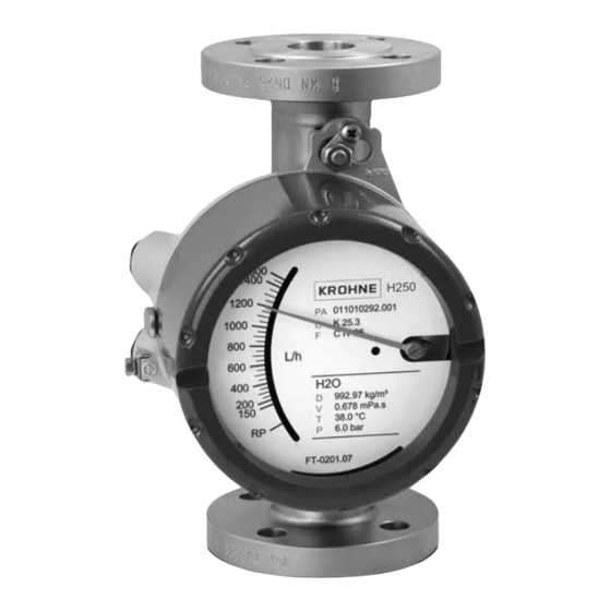
KROHNE H250 M40 Handbook
Variable area flowmeter
Hide thumbs
Also See for H250 M40:
- Handbook (84 pages) ,
- Supplementary instructions manual (24 pages) ,
- Safety manual (20 pages)

Related Manuals for KROHNE H250 M40


Summary of Contents for KROHNE H250 M40
- Page 1 H250 M40 H250 M40 H250 M40 H250 M40 Handbook Handbook Handbook Handbook Variable area flowmeter Electronic revision ESK: up to ER 3.1.x © KROHNE 03/2020 - 4000640706 - MA H250-M40 R06 en...
- Page 2 All rights reserved. It is prohibited to reproduce this documentation, or any part thereof, without the prior written authorisation of KROHNE Messtechnik GmbH. Subject to change without notice. Copyright 2020 by KROHNE Messtechnik GmbH - Ludwig-Krohne-Str. 5 - 47058 Duisburg (Germany) www.krohne.com 03/2020 - 4000640706 - MA H250-M40 R06 en...
- Page 3 CONTENTS H250 M40 1 Safety instructions 1.1 Software history ....................... 6 1.2 Intended use ........................7 1.3 Certifications ........................8 1.4 Pressure equipment directive..................8 1.5 Safety instructions from the manufacturer ..............10 1.5.1 Copyright and data protection ....................10 1.5.2 Disclaimer ..........................
- Page 4 CONTENTS H250 M40 5 Start-up 5.1 Standard device ......................39 5.2 Indicator ESK4-T ......................39 6 Operation 6.1 ESK4A - Loop Check Mode..................... 40 6.2 Operating elements ESK4-T................... 41 6.3 Basic principles of operation ESK4-T ................42 6.3.1 Description of the operating keys..................42 6.3.2 Navigation within the menu structure..................
- Page 5 CONTENTS H250 M40 8 Technical data 8.1 Functional principle......................76 8.2 Technical data......................... 77 8.2.1 Temperatures for mechanical indicators without auxiliary power........79 8.2.2 Temperatures for devices with electrical components ............80 8.2.3 Pressure tightness (vacuum) H250/C................... 81 8.2.4 Process connections......................82 8.2.5 Electrical connections, inputs and outputs ................
- Page 6 SAFETY INSTRUCTIONS H250 M40 1.1 Software history The electronic revision (sticker on the base module ESK4 / ESK4A) indicates the respective hardware/software status of the electronics. All add-on modules (ESK4-T, ESK4-FF and ESK4-PA) have an additional sticker indicating their respective firmware version.
- Page 7 SAFETY INSTRUCTIONS H250 M40 1.2 Intended use CAUTION! Responsibility for the use of the measuring devices with regard to suitability, intended use and corrosion resistance of the used materials against the measured fluid lies solely with the operator. INFORMATION! This device is a Group 1, Class A device as specified within CISPR11:2009. It is intended for use in industrial environment.
- Page 8 SAFETY INSTRUCTIONS H250 M40 1.3 Certifications CE marking The device fulfils all applicable statutory requirements of the EU directives: • Pressure equipment directive • For devices with electrical installations: EMC directive • Devices for use in hazardous areas: ATEX directive as well as •...
- Page 9 SAFETY INSTRUCTIONS H250 M40 Residual risk A risk analysis in accordance with the pressure equipment directive has been carried out for the devices . The residual risk is described as follows: • The devices are designed according to the valid and applicable rules and standards for static operation and their pressure resistance is calculated for the declared maximum pressure and temperature (no calculation for cyclical change).
- Page 10 SAFETY INSTRUCTIONS H250 M40 1.5 Safety instructions from the manufacturer 1.5.1 Copyright and data protection The contents of this document have been created with great care. Nevertheless, we provide no guarantee that the contents are correct, complete or up-to-date. The contents and works in this document are subject to copyright. Contributions from third parties are identified as such.
- Page 11 SAFETY INSTRUCTIONS H250 M40 1.5.3 Product liability and warranty The operator shall bear responsibility for the suitability of the device for the specific purpose. The manufacturer accepts no liability for the consequences of misuse by the operator. Improper installation or operation of the devices (systems) will cause the warranty to be void. The respective "Standard Terms and Conditions"...
- Page 12 SAFETY INSTRUCTIONS H250 M40 1.5.5 Warnings and symbols used Safety warnings are indicated by the following symbols. DANGER! This warning refers to the immediate danger when working with electricity. DANGER! This warning refers to the immediate danger of burns caused by heat or hot surfaces.
- Page 13 DEVICE DESCRIPTION H250 M40 2.1 Scope of delivery INFORMATION! Inspect the packaging carefully for damages or signs of rough handling. Report damage to the carrier and to the local office of the manufacturer. INFORMATION! Do a check of the packing list to make sure that you have all the elements given in the order.
- Page 14 DEVICE DESCRIPTION H250 M40 2.2 Device version • H250 with indicator M40 • H250 with M40 indicator with display cut-out for ESK4-T Figure 2-2: Device version - H250 with M40 indicator Description of the device version 1. H250/RR/M40 • Local indicator without auxiliary power •...
- Page 15 DEVICE DESCRIPTION H250 M40 2.2.1 Indicator versions The M40 indicator can be fitted with various modules. Figure 2-3: Basic version 1 Pointer module 2 Bolts for ESK4A attachment 3 Base plate 4 Module profile 5 Pressure piece for ESK4A attachment...
- Page 16 1 Basic module with electronic magnet sensors ESK4A 2 Connection bus module 3 DIP switch for bus settings For more details refer to the supplementary instructions "H250 M40 Foundation Fieldbus" or "H250 M40 Profibus PA". www.krohne.com 03/2020 - 4000640706 - MA H250-M40 R06 en...
- Page 17 DEVICE DESCRIPTION H250 M40 2.2.2 Float damping Float damping is characterised by high standstill times and self-centering. The damping sleeve is made of high performance ceramic or PEEK, depending on the medium and the application. Float damping can also be retrofitted for the user (refer to "Service").
- Page 18 DEVICE DESCRIPTION H250 M40 2.3 Nameplate INFORMATION! Check on the device nameplates, that the device is supplied according to your order. Figure 2-8: Example of a nameplate 1 Device type 2 Manufacturer 3 Identification number of the notified body 4 Rating data: temperature & pressure rating...
- Page 19 DEVICE DESCRIPTION H250 M40 2.4 Description code The description code consists of the following elements *: Figure 2-9: Description code 1 Device type Device type Device type Device type H250 - standard version H250H - horizontal flow direction H250U - flow direction from top to bottom...
- Page 20 INSTALLATION H250 M40 3.1 General installation notes INFORMATION! Inspect the packaging carefully for damages or signs of rough handling. Report damage to the carrier and to the local office of the manufacturer. INFORMATION! Do a check of the packing list to make sure that you have all the elements given in the order.
- Page 21 INSTALLATION H250 M40 3.4 Installation conditions CAUTION! When installing the device in the piping, the following points must be observed: The variable area flowmeter must be installed vertically (measuring principle). • Flow direction from bottom to top. H250Hs are installed horizontally and H250U devices are installed vertically with the flow direction from top to bottom.
- Page 22 INSTALLATION H250 M40 Minimum distance between devices When several devices are installed next to each other, a minimum distance of > 300 mm / 11.8" between the devices is necessary. Figure 3-1: Minimum distance between devices Take special note of the installation position for the H250H with horizontal flow...
- Page 23 INSTALLATION H250 M40 3.4.1 Tightening torques For devices with PTFE liner or ceramic liner and PTFE raised face, tighten the flange threads with the following torques: Nominal size according to Stud bolts Max. torque EN 1092-1 ASME B16.5 ASME EN 1092-1...
- Page 24 INSTALLATION H250 M40 3.4.3 Heat insulation CAUTION! The indicator housing may not be heat-insulated. The heat insulation 3 may only reach as far as the housing fastening 4. Figure 3-4: Heat insulation 1 Standard indicator M40 2 Indicator with HT extension CAUTION! The heat insulation 1 may only reach to the rear of the housing 2.
- Page 25 ELECTRICAL CONNECTIONS H250 M40 4.1 Safety instructions DANGER! All work on the electrical connections may only be carried out with the power disconnected. Take note of the voltage data on the nameplate! DANGER! Observe the national regulations for electrical installations! DANGER! For devices used in hazardous areas, additional safety notes apply;...
- Page 26 ELECTRICAL CONNECTIONS H250 M40 4.2 Electrical connection for indicator M40 4.2.1 Connection of the limit switches K1/K2 The M40 indicator can be fitted with a maximum of two limit switches. The limit switch operates as a proximity switch which is activated inductively by the semicircular metal vane of the pointer.
- Page 27 ELECTRICAL CONNECTIONS H250 M40 Connection diagram for the limit switches Figure 4-2: Connection terminals for limit switches 1 Limit switch 2-wire NAMUR 2 Limit switch 3-wire 3 Limit switch Reed SPST 4 Terminal connection of Min. contact 5 Terminal connection of Max. contact...
- Page 28 ELECTRICAL CONNECTIONS H250 M40 After the setting: • Pull the upper scale support 2 mm / 0.08" flexibly upwards and pull out the scale again from its locking point to the side. • Tighten the locking screw 3 with max. 0.2 Nm.
- Page 29 ELECTRICAL CONNECTIONS H250 M40 4.2.2 Current output ESK4A The connecting terminals of the ESK4A have a pluggable design and can be removed in order to connect the cables. Figure 4-6: ESK4A connection 1 Current output of ESK4A 2 Power supply 14...32 VDC (intrinsicallly safe max. 30 VDC) 3 Measuring signal 4...20 mA...
- Page 30 ELECTRICAL CONNECTIONS H250 M40 Power supply INFORMATION! The supply voltage has to be between 14 VDC and 32 VDC. This is based on the total resistance of the measuring loop. To calculate this, the resistance of each component in the measuring loop (not including the device) must be added up.
- Page 31 ELECTRICAL CONNECTIONS H250 M40 ® Load for HART communication INFORMATION! communication a load of at least 250 Ω is required. ® For HART The maximum load resistance is calculated as follows: = (U - 14 V) / 22 mA ext.
- Page 32 ELECTRICAL CONNECTIONS H250 M40 4.2.3 ESK4-T limit outputs Once the housing cover has been unscrewed, the scale can be removed. The connection terminals have a pluggable design and can be removed to connect the cables. Figure 4-8: Position of the connection terminals...
- Page 33 ELECTRICAL CONNECTIONS H250 M40 Figure 4-9: Connection switching output 1 NAMUR terminal connection 2 Isolated switching amplifier 3 OC switch output terminal connection 4 Power supply U ext. 5 Load R NC contact NO contact Switching value reached < 1 mA >...
- Page 34 ELECTRICAL CONNECTIONS H250 M40 4.2.4 ESK4-T pulse output INFORMATION! The binary outputs can also be operated as pulse outputs. When using the binary outputs as a pulse output, two separate signal circuits are required. Each signal circuit requires its own power supply.
- Page 35 ELECTRICAL CONNECTIONS H250 M40 4.2.5 ESK4-T binary input The binary input can be used to control the internal flow counter (start/stop/reset). Binary input Terminal no. Connection Table 4-7: Value range for NAMUR Figure 4-12: Binary input 1 Function active HI...
- Page 36 ELECTRICAL CONNECTIONS H250 M40 4.2.6 ESK4-FF / ESK4-PA fieldbus communication Figure 4-13: ESK4-FF / ESK4-PA fieldbus communication 1 FF HSE Bus / Profibus DP 2 Linking device / bus coupler 3 FF H1 Bus / Profibus PA, 2-wire with shielding...
- Page 37 ELECTRICAL CONNECTIONS H250 M40 4.2.7 Harting HAN 7D connection Figure 4-14: Terminal assignment ® 1 Terminal assignment of HAN 7D - View of plug connection K1/K2 NAMUR R1/R2 Reed ESK4A Terminal number ® 1 Pin number HAN contacts contacts NAMUR...
- Page 38 ELECTRICAL CONNECTIONS H250 M40 4.3 Grounding connections Figure 4-15: Grounding connections 1 Grounding connection on the indicator 2 Outer grounding connection DANGER! The grounding wire may not transfer any interference voltage. Do not use this grounding cable to ground any other electrical devices.
- Page 39 START-UP H250 M40 5.1 Standard device CAUTION! When starting up the device, the following points must be observed: Compare the actual operating pressure and the product temperature of the system with the • specifications on the nameplate (PS and TS). These specifications may not be exceeded.
- Page 40 OPERATION H250 M40 6.1 ESK4A - Loop Check Mode The ESK4A is equipped with a loop check function, enabling a simple test of the entire 4…20 mA current loop. It is activated and operated using a microswitch 1. Figure 6-1: Position of the microswitch...
- Page 41 OPERATION H250 M40 6.2 Operating elements ESK4-T The device is operated with the cover on the front open, using the mechanical keys keys, or with the keys keys cover closed using a bar magnet bar magnet bar magnet bar magnet.
- Page 42 OPERATION H250 M40 6.3 Basic principles of operation ESK4-T 6.3.1 Description of the operating keys Switch from measuring mode to menu mode → Switch to one menu level lower Open menu item and activate change mode Confirm query whether data should be accepted...
- Page 43 OPERATION H250 M40 6.3.3 Change the settings in the menu Starting operation Operation is started using the → key. If an operation lock is set, the code (→ → → ^ ^ ^ ↑ ↑ ↑) must be entered. The code can be set in menu 3.15.
- Page 44 OPERATION H250 M40 6.4 Overview of the units ESK4-T Volume units can either represent real operating volumes (no prefix before the unit) or standard volumes virtually converted to reference standard conditions. Prefix Volume definition None Operating volume flow e.g. m /h or ft Volume flow at standard (norm.) conditions (0°C - 1.013 bara) acc.
- Page 45 OPERATION H250 M40 6.5 Error messages ESK4-T Error messages and warnings are indicated by one of the following symbols in the bottom left corner of the display. The ^ ^ ^ ^ key switches from the measured value display to the display of current errors / warnings.
- Page 46 OPERATION H250 M40 Error message Description Category Remedy NO ZERO CAL The current output zero Perform calibration using ammeter and menu OF AO point 4.00mA is not ® 3.10 or using standard HART tools/process calibrated. = possible control system and poss. external ammeter.
- Page 47 OPERATION H250 M40 Error message Description Category Remedy ERROR TIMEOUT Data not transferred, or Confirm menu item "1.6.3 WRITE INFO I/O". transferred incorrectly WARNING TIMEOUT from the ESK to the counter module. ESK4A - Loop LOOP CHECK Loop check function is For further information refer to active.
- Page 48 OPERATION H250 M40 6.6 ESK4-T menu 6.6.1 Factory settings Function Setting 1.1.1 OUTPUT B1 INACTIVE 1.2.1 OUTPUT B2 INACTIVE 1.3.1 PULSE WIDTH 50ms 1.3.2 PULSE/UNIT 1 Pulse/Unit 1.4 DISPLAY MEAS’D VALUE 1.4.2 ROTATION 0° 1.5 TIME CONST 1.0s 1.6.1 COUNTER 1.6.2 ERROR...
- Page 49 OPERATION H250 M40 Function Setting 5.3.2 MAG. FIELD Maintenance required 5.3.3 PUL. FLOW Out of Specification 5.4 BLOCKED FL. 5.4.1 PERIOD 1800 s 5.4.2 MIN. FLOW 50 % 5.4.3 THRESHOLD 0.075 % 5.5 EXT. MAG. F. 5.5.1 HOLD TIME 4.0 s 5.5.2 MIN MAG...
- Page 50 OPERATION H250 M40 6.6.2 Menu structure Main menu Submenu 1 Submenu 2 1 OPERATION 1.1 OUTPUT B1 1.1.1 INACTIVE, MEAS.VAL. B1, CNT. VAL. B1, PULSE WIDTH 1.1.2 HYST. B1, PULSE/UNIT 1.2 OUTPUT B2 1.2.1 INACTIVE, MEAS.VAL. B2, CNT. VAL. B2, PULSE WIDTH 1.2.2 HYST.
- Page 51 OPERATION H250 M40 Main menu Submenu 1 Submenu 2 2 TEST & INFO 2.7 SOFT.VERSION 2.7.1 FW. ESK4 2.7.2 FW. ESK4 I/O 2.8 TAG NB. 8 characters 2.9 LONG TAG 32 characters 3 INSTALLATION 3.1 LANGUAGE 3.1.1 ENGLISH 3.1.2 DEUTSCH 3.1.3 FRANCAIS...
- Page 52 OPERATION H250 M40 Main menu Submenu 1 Submenu 2 5 NE107 DIAG. 5.3 MAP EVENT 5.3.1 BLOCKED FL. 5.3.2 MAG. FIELD 5.3.3 PUL. FLOW 5.4 BLOCKED FL. 5.4.1 PERIOD 5.4.2 MIN. FLOW 5.4.3 THRESHOLD 5.5 EXT. MAG. F. 5.5.1 HOLD TIME 5.5.2 MIN MAG...
- Page 53 OPERATION H250 M40 6.6.3 Menu description 1 OPERATION Selection / Input Explanation 1.1 OUTPUT B1 1.1 OUTPUT B1 Output B1 is a binary switching output. In Fct. 3.2, one of the following functions can be 1.1 OUTPUT B1 1.1 OUTPUT B1 selected for this output: INACTIVE, SWITCH POINT, COUNT.
- Page 54 OPERATION H250 M40 Selection / Input Explanation 1.2 OUTPUT B2 1.2 OUTPUT B2 1.2 OUTPUT B2 1.2 OUTPUT B2 Output B2 is a binary switching output. In Fct. 3.4, one of the following functions can be selected for this output: INACTIVE, SWITCH POINT, COUNT.
- Page 55 OPERATION H250 M40 1.4 DISPLAY 1.4 DISPLAY 1.4 DISPLAY 1.4 DISPLAY Different measured values can be selected for permanent or alternating display. The reading on the display can be rotated. 1.4.1 MEAS’D VALUE Permanent display of flow in flow units...
- Page 56 OPERATION H250 M40 2 TEST & INFO Selection / Input Explanation 2.1 4-20mA OUTP 2.1 4-20mA OUTP 2.1 4-20mA OUTP 2.1 4-20mA OUTP Testing the current loop by setting various current values. Note: Note: Note: Note: ® The test is not available in HART multi-drop mode (refer to Fct.
- Page 57 OPERATION H250 M40 Selection / Input Explanation 2.6 DEV. IDENT. 2.6 DEV. IDENT. Information for device identification 2.6 DEV. IDENT. 2.6 DEV. IDENT. 2.6.1 ELEC. REV. Electronic revision 2.6.2 SN ESK4 Serial number ESK4 2.6.3 PROD. ORDER Production order for the complete flowmeter 2.6.4 DEV.
- Page 58 OPERATION H250 M40 Selection / Input Explanation 3.4 FUNCTION B2 3.4 FUNCTION B2 3.4 FUNCTION B2 3.4 FUNCTION B2 INACTIVE Refer to FUNCTION B1 SWITCH POINT Refer to FUNCTION B1 Configuration of the switching point is in Fct. 1.2.1 MEAS.VAL. B2.
- Page 59 OPERATION H250 M40 Selection / Input Explanation ALARM LOW Error indication via the current loop is activated (failure signal "low" acc. to NE43). Note: Note: Note: Note: ® 1) This function is not available in HART multi-drop mode. 2) This function is supported from ER 2.2.x.
- Page 60 OPERATION H250 M40 5 NE107 DIAG. Selection / Input Explanation 5.1 DIS/ENABLE 5.1 DIS/ENABLE 5.1 DIS/ENABLE 5.1 DIS/ENABLE The different application diagnostic functions can be switched on/off separately. 5.1.1 BLOCKED FL. Detection of blocked float. Not active. Active 5.1.2 EXT. MAG. F.
- Page 61 OPERATION H250 M40 Selection / Input Explanation 0: No effect No status signal 1: Maint. Req. Status signal: Maintenance required 3: Failure Status signal: Failure 4: Out Of Spec Status signal: Out of Specification 5: Fnc. Chk. Status signal: Function check 5.3.3 PUL.
- Page 62 SERVICE H250 M40 7.1 Maintenance Within the scope of routine maintenance of the system and pipelines, the flowmeter should also be inspected for signs of fouling, corrosion, mechanical wear and leaks, as well as damage to the measuring tube and the indicator.
- Page 63 SERVICE H250 M40 7.2.2 Retrofitting of the float damping • Take the upper span ring 1 out of the measuring unit. • Take the upper float stop 2 and float 5 out of the measuring unit. • Fasten the retaining ring 3 into the lower slot of the float's guide rod.
- Page 64 SERVICE H250 M40 7.2.3 Retrofitting of the limit switch • Remove ESK4A add-on module (if available). • Merge contact pointer 2 in the middle. • Loosen the locking screw 1 on the contact pointer. • Insert the contact module into slot 3 of the bracket until the semi-circle 1 on the contact board surrounds the pointer cylinder.
- Page 65 SERVICE H250 M40 7.2.4 Replacement - Retrofitting ESK4A CAUTION! When replacing or retrofitting an ESK4A, it is mandatory to indicate the serial number (SN) or sales order (SO) when ordering. This information can be found on the indicator nameplate. The ESK4A is factory calibrated, making it possible to replace it or retrofit it without recalibrating.
- Page 66 SERVICE H250 M40 7.2.5 Replacement - Retrofitting add-on module ESK4-T / PA / FF The add-on module for the ESK4A can be replaced or retrofitted on-site without removing the device from the process control. • ESK4-T (Display module with LCD and I/O) •...
- Page 67 SERVICE H250 M40 Spare part Order number DN50 DN50 DN50 DN50 Float CIV 55, 1.4404 X253041000 Float DIV 55, 1.4404 X253042000 Float TIV55, 1.4404 X253043000 Float DIVT 55, 1.4404 X253044000 Set float stop; standard (1 float stop, 1 span ring) X253050100 Set float stop;...
- Page 68 SERVICE H250 M40 Indicator M40 Indicator M40 Indicator M40 Indicator M40 Housing components Housing components Housing components Housing components Standard indicator housing M40 complete, no scale * X251110000 Standard indicator housing M40R complete, no scale* (stainless steel, non-coated) X251111000 Standard cover M40...
- Page 69 SERVICE H250 M40 Electronic modules Electronic modules Electronic modules Electronic modules ESK4A, ESK4-FF, ESK4-PA, ESK4-FF (serial number required) Cover for add-on modules X251121500 Connection cable ESK4A to add-on modules X251121600 Plugs (10 pcs) for ESK4A connection for bus modules X251132500...
- Page 70 SERVICE H250 M40 7.5 Returning the device to the manufacturer 7.5.1 General information This device has been carefully manufactured and tested. If installed and operated in accordance with these operating instructions, it will rarely present any problems. WARNING! Should you nevertheless need to return a device for inspection or repair, please pay strict...
- Page 71 SERVICE H250 M40 7.5.2 Form (for copying) to accompany a returned device CAUTION! To avoid any risk for our service personnel, this form has to be accessible from outside of the packaging with the returned device. Company: Address: Department: Name:...
- Page 72 SERVICE H250 M40 7.7 Disassembly and recycling This section describes how to handle and disassemble the device in order to dispose of it following end of use. The information provided enables the end user to identify and separate the main components of the device for the purpose of recycling.
- Page 73 SERVICE H250 M40 7.7.2 Indicator versions The following discusses the indicator housing and optional electronics in more detail. The indicator housing can be fitted with various electronic modules. These can be easily removed from the housing in order to send them to electronics recycling/disposal.
- Page 74 SERVICE H250 M40 Figure 7-6: Versions K1 / K2 and ESK4A 1 Indicator with K2 contact module 2 Indicator with ESK4A current output 4...20 mA Figure 7-7: Version ESK4-T 1 ESK4A connection 2 Module cover 3 Display 4 Display module ESK4-IO 5 Operating keys ^ ↑...
- Page 75 SERVICE H250 M40 Figure 7-8: Version Fieldbus ESK4-FF / ESK4-PA 1 Basic module with electronic magnet sensors ESK4A 2 Connection bus module 3 DIP switch for bus settings Approx. information ESK4A ESK4-IO ESK4-FF / Contact module ESK4-PA K1/K2 68 cm² / 10.5 in²...
- Page 76 TECHNICAL DATA H250 M40 8.1 Functional principle The H250 flowmeter operates in accordance with the float measuring principle. The measuring unit consists of a metal cone in which a float can move freely up and down. The medium flows through the flowmeter from bottom to top. The float adjusts itself so that the buoyancy force F1...
- Page 77 TECHNICAL DATA H250 M40 8.2 Technical data INFORMATION! • The following data is provided for general applications. If you require data that is more relevant to your specific application, please contact us or your local sales office. Additional information (certificates, special tools, software,...) and complete product •...
- Page 78 TECHNICAL DATA H250 M40 Pressure Pressure Pressure Pressure Max. operating pressure PS, max. test Depending on the version (refer to nameplate) pressure PT Min. required operating pressure 2 times greater than pressure loss (refer to measuring ranges) Pressure tightness (vacuum) H250/C...
- Page 79 TECHNICAL DATA H250 M40 Indicators Indicators Indicators Indicators Aluminium, two-layer powder coating (epoxy / polyester) M40R Stainless steel without coating 1.4408 / CF8M Offshore Wet coating on request Cable glands Standard Polyamide Optional Nickel-plated brass or stainless steel Other options on request...
- Page 80 TECHNICAL DATA H250 M40 8.2.2 Temperatures for devices with electrical components DANGER! For devices to be used in hazardous areas, special temperature ranges apply. These can be found in the Ex supplementary instructions. Type Ambient temperature [°C] [°F] ESK4A, ESK4-FF, ESK4-PA 1 -40...+70...
- Page 81 TECHNICAL DATA H250 M40 Maximum product temperature in °F < +104°F < +140°F 1 ASME Version with Standard HT Standard HT DN15, 1/2", 1" ESK4A, ESK4-FF, ESK4-PA DN25 ESK4-T Limit switch NAMUR Limit switch 3-wire DN50 2" ESK4A, ESK4-FF, ESK4-PA...
- Page 82 TECHNICAL DATA H250 M40 8.2.4 Process connections Standard Dimensions Pressure rating Flanges (H250/RR /HC /C) EN 1092-1 DN15...150 PN16...250 ASME B16.5 1/2...6" 150...2500 lb JIS B2220 15…100 10...20K Clamp connections (H250/RR /F) DIN 32676 DN15...100 10...16 bar ISO 2852 Size 25...139.7 10...16 bar...
- Page 83 ® ESK4A HART configuration Manufacturer name (code) KROHNE Messtechnik (0x45 = 69) ESK4A (17854 = 0x45BE) / HART 7.4 ® Model name / HART revision Physical Layer 03/2020 - 4000640706 - MA H250-M40 R06 en...
- Page 84 23 mA Boot-up current after 10 ms < Nominal current Table 8-11: ESK4-FF INFORMATION! For more details refer to the supplementary instructions "H250 M40 Foundation Fieldbus". ESK4-PA Profibus PA Physical Layer IEC 61158-2 and FISCO model Communication standard Profibus PA profile 3.02...
- Page 85 TECHNICAL DATA H250 M40 ESK4-T with LCD, binary inputs and outputs and digital counter Binary output Two binary outputs Galvanically isolated, passive Mode Switching output NAMUR or transistor (OC) Configurable as switch contact or pulse output NC / NO or max. 10 pulses/s...
- Page 86 TECHNICAL DATA H250 M40 8.2.6 Ex approvals Approval Indicator type Marking ATEX / IECEx M40 mechanical II2GD IIC Ex h II3GD IIIC Ex h M40 electrical II2G Ex ia IIC T6 Gb II2G Ex db IIC T6 Gb II3G Ex nA/ec IIC T6 Gc II2D Ex tb IIIC T70°C Db...
- Page 87 TECHNICAL DATA H250 M40 8.3 Dimensions and weight Front view Side view with heating High-temperature [mm] ["] [mm] ["] [mm] ["] [mm] ["] H250/RR flange, 5.56 9.85 5.91 5.91 H250/F Clamp connection H250/RR from 2" 600 lb, 11.82 ISO 228, ASME B1.20.1, SMS ASME Ø...
- Page 88 TECHNICAL DATA H250 M40 Weight H250 Heating Nominal size EN 1092-1 with flange connection with Ermeto connection ASME [kg] [lb] [kg] [lb] [kg] [lb] DN15 1/2" 12.6 DN25 1" 16.5 12.8 DN50 2" 18.1 11.2 24.7 DN80 3" 12.2 26.9 14.8...
- Page 89 TECHNICAL DATA H250 M40 ® 8.4.1 H250/HC - Hastelloy , H250/RR - stainless steel Water Max. pressure loss Float Alu. Alu. Nominal Cone [l/h] [mbar] size DN15, 1/2" K 15.1 0.42 0.65 K 15.2 K 15.3 K 15.4 K 15.5 K 15.6...
- Page 90 TECHNICAL DATA H250 M40 Water Max. pressure loss Float Alu. Alu. Nominal Cone [GPH] [SCFM] [psig] size DN15, 1/2" K 15.1 4.76 6.60 0.26 0.40 0.18 0.31 0.38 K 15.2 7.93 10.6 0.43 0.62 0.18 0.31 0.38 K 15.3 14.5 16.6...
- Page 91 TECHNICAL DATA H250 M40 8.4.2 H250/C - Ceramic/PTFE Flow rate Max. pressure loss Water Water Liner / Float PTFE Ceram. PTFE Ceram. PTFE Ceram. PTFE Ceram. Nominal Cone [l/h] [mbar] size DN15, 1/2" E 17.2 E 17.3 E 17.4 E 17.5 E 17.6...
- Page 92 TECHNICAL DATA H250 M40 Flow rate Max. pressure loss Water Water Liner / Float PTFE Ceram. PTFE Ceram. PTFE Ceram. PTFE Ceram. Nominal Cone [GPH] [SCFM] [psig] size DN15, 1/2" E 17.2 6.60 7.93 0.43 0.94 0.90 0.94 0.90 E 17.3 10.6...
- Page 93 TECHNICAL DATA H250 M40 8.4.3 H250/RR (Low flow) Flow, water Flow, air Pressure loss Nominal Cones Float [l/h] [GPH] [Nl/h] [SCFH] [mbar] [psi] size DN15, 1/2" K 005 N3 titanium 1 0.25 K 005 N1 titanium 1 K 005 N1 Stainless steel 0.45...
- Page 94 TECHNICAL DATA H250 M40 8.4.4 H250H - Horizontal installation position ASME Cone Water [l/h] Pressure loss Air [Nm [mbar] DN15 1/2" K 15.1 K 15.2 K 15.3 K 15.4 K 15.5 K 15.6 K 15.7 1200 K 15.8 1600 K 15.8...
- Page 95 TECHNICAL DATA H250 M40 ASME Cone Water [GPH] Air [SCFM] Pressure loss [psig] DN15 1/2" K 15.1 18.5 1.12 2.87 K 15.2 31.7 1.86 3.00 K 15.3 47.6 2.79 2.87 K 15.4 74.0 4.65 3.31 K 15.5 7.44 3.68 K 15.6 11.2...
- Page 96 TECHNICAL DATA H250 M40 8.4.5 H250U - Vertical installation position Flow direction: vertical downwards ASME Cone Water [l/h] Pressure loss Air [Nm [mbar] DN15 1/2" K 15.1 K 15.2 K 15.3 K 15.4 K 15.5 K 15.6 K 15.7 1100 K 15.8...
- Page 97 NOTES H250 M40 03/2020 - 4000640706 - MA H250-M40 R06 en www.krohne.com...
- Page 98 NOTES H250 M40 www.krohne.com 03/2020 - 4000640706 - MA H250-M40 R06 en...
- Page 99 NOTES H250 M40 03/2020 - 4000640706 - MA H250-M40 R06 en www.krohne.com...
- Page 100 • Process Analysis • Services Head Office KROHNE Messtechnik GmbH Ludwig-Krohne-Str. 5 47058 Duisburg (Germany) Tel.: +49 203 301 0 Fax: +49 203 301 10389 info@krohne.com The current list of all KROHNE contacts and addresses can be found at: www.krohne.com...
Need help?
Do you have a question about the H250 M40 and is the answer not in the manual?
Questions and answers