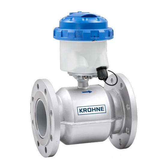
KROHNE WATERFLUX 3070 Handbook
Battery powered electromagnetic water meter with optional krohne flexpower
Hide thumbs
Also See for WATERFLUX 3070:
- Quick start manual (40 pages) ,
- Quick start (4 pages) ,
- Quick start (2 pages)
Table of Contents
Advertisement
Advertisement
Table of Contents

Related Manuals for KROHNE WATERFLUX 3070


Summary of Contents for KROHNE WATERFLUX 3070
- Page 1 WATERFLUX 3070 WATERFLUX 3070 WATERFLUX 3070 WATERFLUX 3070 Handbook Handbook Handbook Handbook Battery powered electromagnetic water meter with optional KROHNE FlexPower Electronic Revision 5.0.2_ (SW.REV.5.0.2_) © KROHNE 06/2016 - 4004999701 - MA WATERFLUX 3070 - R01 en...
- Page 2 All rights reserved. It is prohibited to reproduce this documentation, or any part thereof, without the prior written authorisation of KROHNE Messtechnik GmbH. Subject to change without notice. Copyright 2016 by KROHNE Messtechnik GmbH - Ludwig-Krohne-Str. 5 - 47058 Duisburg (Germany) www.krohne.com 06/2016 - 4004999701 - MA WATERFLUX 3070 - R01 en...
-
Page 3: Table Of Contents
3.8.2 Closing of the converter housing..................25 3.8.3 Mounting of the KROHNE FlexPower ................... 26 4 Electrical connections 4.1 Safety instructions......................27 4.2 Important notes on electrical connection..............27 06/2016 - 4004999701 - MA WATERFLUX 3070 - R01 en www.krohne.com... - Page 4 6.3.12 Battery settings........................60 6.3.13 Modbus settings ........................61 6.4 Tests ..........................62 6.4.1 Automatic self-test ....................... 62 6.4.2 Verification mode ........................62 6.4.3 Test mode..........................62 7 Service www.krohne.com 06/2016 - 4004999701 - MA WATERFLUX 3070 - R01 en...
- Page 5 8.6.2 MID Annex III (MI-001)......................82 8.6.3 Verification to MID Annex III (MI-001) and OIML R49 ............84 8.7 Measurement accuracy....................85 8.7.1 WATERFLUX 3070 without straight inlet and outlet sections ..........86 8.8 Dimensions and weights ....................87 8.9 Pressure loss........................89 8.10 Battery lifetime ......................
-
Page 6: Safety Instructions
(SW. REV. 5.0.1_) 2016 ER 5.0.2_ MA WATERFLUX 3070 V3-R01 (SW. REV. 5.0.2_) * See the KROHNE website, for earlier software versions used in previous versions of the WATERFLUX 3070 www.krohne.com 06/2016 - 4004999701 - MA WATERFLUX 3070 - R01 en... -
Page 7: Intended Use
CE declaration or the website of the manufacturer. Other approvals and standards • Measuring Instruments Directive 2014/32/EU - Annex III (MI-001) For more information, please refer to the dedicated documentation. 06/2016 - 4004999701 - MA WATERFLUX 3070 - R01 en www.krohne.com... -
Page 8: Safety Instructions From The Manufacturer
The manufacturer reserves the right to alter the content of its documents, including this disclaimer in any way, at any time, for any reason, without prior notification, and will not be liable in any way for possible consequences of such changes. www.krohne.com 06/2016 - 4004999701 - MA WATERFLUX 3070 - R01 en... -
Page 9: Product Liability And Warranty
This document is provided to help you establish operating conditions, which will permit safe and efficient use of this device. Special considerations and precautions are also described in the document, which appear in the form of icons as shown below. 06/2016 - 4004999701 - MA WATERFLUX 3070 - R01 en www.krohne.com... -
Page 10: Warnings And Symbols Used
In general, devices from the manufacturer may only be installed, commissioned, operated and maintained by properly trained and authorized personnel. This document is provided to help you establish operating conditions, which will permit safe and efficient use of this device. www.krohne.com 06/2016 - 4004999701 - MA WATERFLUX 3070 - R01 en... -
Page 11: Instruction For Transportation And Handling Of Batteries
• Remove the battery from device before returning to the manufacturer for service or warranty reasons. • Dispose battery packs in accordance with local regulations; where possible, recycle used batteries. 06/2016 - 4004999701 - MA WATERFLUX 3070 - R01 en www.krohne.com... -
Page 12: Device Description
The converter housing is delivered with attached IP67 dust caps to protect the connections of the converter. After removing the caps and connecting the signal- and sensor cables, the converter housing and connections are IP68 rated. www.krohne.com 06/2016 - 4004999701 - MA WATERFLUX 3070 - R01 en... -
Page 13: Device Description
Product specific information and extensive product specification is available using PICK, the Product Information Center KROHNE web-tool. PICK can be found via the service menu button on the KROHNE.com website. The following versions are available: • Compact version (the signal converter is mounted directly on the measuring sensor) in polycarbonate (IP68) housing •... -
Page 14: Nameplate (Example)
5 Meter constant, diameter, wetted materials, protection class 6 Type designation of the flowmeter, serial number, date of manufacturing (option: text P&T only for versions with integrated pressure and temperature sensor) www.krohne.com 06/2016 - 4004999701 - MA WATERFLUX 3070 - R01 en... -
Page 15: Installation
• Do not lift the device by the signal converter housing. • Do not use lifting chains. • To transport flange devices, use lifting straps. Wrap these around both process connections. Figure 3-1: Transport 06/2016 - 4004999701 - MA WATERFLUX 3070 - R01 en www.krohne.com... -
Page 16: Pre-Installation Requirements
Do not expose the signal converter to intense vibration. The flowmeters are tested for a vibration level in accordance with IEC 68-2-64. 3.5.1 Vibration Figure 3-2: Avoid vibrations 3.5.2 Magnetic field Figure 3-3: Avoid magnetic fields www.krohne.com 06/2016 - 4004999701 - MA WATERFLUX 3070 - R01 en... -
Page 17: Installation Conditions
2 Outlet: ≥ 0 DN 3.6.2 T-section Figure 3-5: Distance behind a T-section 1 ≥ 0 DN 3.6.3 Open feed or discharge Figure 3-6: Installation in front of an open discharge 06/2016 - 4004999701 - MA WATERFLUX 3070 - R01 en www.krohne.com... -
Page 18: Bends
Figure 3-8: Installation in bending pipes CAUTION! Avoid draining or partial filling of the flow sensor 3.6.5 Pump Figure 3-9: Recommended installation: behind a pump 1 Inlet: ≥ 3 DN www.krohne.com 06/2016 - 4004999701 - MA WATERFLUX 3070 - R01 en... -
Page 19: Control Valve
Figure 3-10: Recommended installation: in front of a control valve 3.6.7 Air venting and vacuum forces Figure 3-11: Air venting 1 ≥ 5 m 2 Air ventilation point Figure 3-12: Vacuum 1 ≥ 5 m 06/2016 - 4004999701 - MA WATERFLUX 3070 - R01 en www.krohne.com... -
Page 20: Installation In A Metering Pit And Subsurface Applications
Subsurface application Figure 3-14: Application with buried (subsoil) sensor and a field version converter 1 WATERFLUX 3070 remote version Note: figures shows a cable ≤ 25 m / 82 ft www.krohne.com 06/2016 - 4004999701 - MA WATERFLUX 3070 - R01 en... -
Page 21: Mounting Position And Flange Deviation
≤ 0.5 mm / 0.02". Max. permissible deviation of pipe flange faces: L CAUTION! Use the proper tools to ensure the integrity of the meter and prevent damage to the Rilsan ® coating. 06/2016 - 4004999701 - MA WATERFLUX 3070 - R01 en www.krohne.com... -
Page 22: Mounting
• Step 1: Apply approx. 50% of max. torque given in table. • Step 2: Apply approx. 80% of max. torque given in table. • Step 3: Apply 100% of max. torque given in table. www.krohne.com 06/2016 - 4004999701 - MA WATERFLUX 3070 - R01 en... - Page 23 1 The torque values also depend on variables (temperature, bolt material, gasket material, lubricants, etc.) outside the control of the manufacturer. Therefore these values should be regarded as indicative only. 06/2016 - 4004999701 - MA WATERFLUX 3070 - R01 en www.krohne.com...
- Page 24 1 The torque values also depend on variables (temperature, bolt material, gasket material, lubricants, etc.) outside the control of the manufacturer. Therefore these values should be regarded as indicative only. 2 No full rating (max. 150 psi / 10 bar). www.krohne.com 06/2016 - 4004999701 - MA WATERFLUX 3070 - R01 en...
-
Page 25: Mounting Of The Signal Converter
2 are inline (do not tighten the ring any further). • Use the special wrench to tighten the ring as advised above. • If applicable, place a new utility seal (see section Utility Seal) 06/2016 - 4004999701 - MA WATERFLUX 3070 - R01 en www.krohne.com... -
Page 26: Mounting Of The Krohne Flexpower
Mounting on the pipe line construction can easily be done by using 2 Tie-Wraps. The bottom of the housing of the KROHNE FlexPower unit is designed for mounting on a pipe line. Choose the correct size and properties of the Tie-Wraps ( specifications according ambient temperature and other conditions, size, width max.14 mm / ½... -
Page 27: Electrical Connections
DN size and GK/GKL of the sensor, refer to the chapter; Function Function Function Function tables tables of the concerning signal converter. tables tables DANGER! Cables may only be connected when the power is switched off. 06/2016 - 4004999701 - MA WATERFLUX 3070 - R01 en www.krohne.com... -
Page 28: Grounding
ELECTRICAL CONNECTIONS WATERFLUX 3070 4.3 Grounding Figure 4-1: Grounding INFORMATION! Grounding without grounding rings. The flow sensor is equipped with a reference electrode. www.krohne.com 06/2016 - 4004999701 - MA WATERFLUX 3070 - R01 en... -
Page 29: Cable Overview
The sensor cable for the IP68 remote (field) version has an 8 pins male connector. The I/O cable (pulse /modbus) is available in a KROHNE FlexPower version and has an additional power cable connection. Overview I/O cables, with or without a power cable, with female connector:... -
Page 30: Connection Of The Sensor Cable
For the WATERFLUX 3070 (F) remote version, a standard cable is delivered with the device. On the sensor side the cable is standard potted at the factory. The sensor cable has a IP68 rated RVS... -
Page 31: Connection Of The Signal Cable
Pink Up link wire A→ Green Down link wire A← White Ground Brown Shield Earth Note: See for the combined power and modbus / pulse cable options, next chapter. 06/2016 - 4004999701 - MA WATERFLUX 3070 - R01 en www.krohne.com... -
Page 32: Ip68 Housing (Remote Version)
Contact on Function connector Yellow Down link wire B← Grey Up link wire B→ Pink Up link wire A→ Green Down link wire A← White Ground Brown Shield Earth www.krohne.com 06/2016 - 4004999701 - MA WATERFLUX 3070 - R01 en... - Page 33 For proper use and installation, it is recommended to follow the advised color coded wire connections in the table above.A 120Ω line terminator is required when the WATERFLUX 3070 converter is the last device in line and/or is part of the bus connection.
-
Page 34: Start-Up
For information on the different battery types refer to on page 63 INFORMATION! The device now operates with default menu settings. refer to Battery settings on page 60 for configuration of these menu settings. www.krohne.com 06/2016 - 4004999701 - MA WATERFLUX 3070 - R01 en... -
Page 35: Connecting The External Battery
60 for more information regarding the battery menu settings 5.3 Power supply - battery The standard version of the WATERFLUX 3070 has an internal battery pack with a Lithium double D cell (3.6V-38 Ah). Optional an KROHNE PowerBlock (Lithium Dual DD cell 3.6V-70 Ah) can be connected with an IP68 rated, 1.5 meter long cable. -
Page 36: Connection Of The Flexpower Unit
Optionally, beside an internal or external battery, the WATERFLUX3070 can be connected to an external FlexPower unit for mains power and/or DC power operation with battery back-up. The input power for the KROHNE FlexPower can be realized by connection to an AC / DC supply source •... -
Page 37: Starting The Signal Converter
The measuring device consist of a sensor and a converter and is ready for operation. When the power is switched on (battery or FlexPower unit is connected), a self-test is carried out and after that, the meter starts to operate 06/2016 - 4004999701 - MA WATERFLUX 3070 - R01 en www.krohne.com... -
Page 38: Operation
4 Reset button only accessible after removing the housing Optional P&T sensor 1 Display showing temperature value 2 Display showing pressure value www.krohne.com 06/2016 - 4004999701 - MA WATERFLUX 3070 - R01 en... -
Page 39: Show Counters And Flow Rate On The Display
Description (default) - ∑ + + ∑ - Sum counter (default) ∑ + + ∑ Forward counter - ∑ ∑ - Reverse counter Positive flow rate Negative flow rate 06/2016 - 4004999701 - MA WATERFLUX 3070 - R01 en www.krohne.com... -
Page 40: Show Software Version, Diameter, Meter Constant And Display Test On The Display
Example Example Example of the diameter (125) and the meter constant (4.160) Example Example of the add-on software version Example Example Example Example Example Example Modbus version Display test www.krohne.com 06/2016 - 4004999701 - MA WATERFLUX 3070 - R01 en... -
Page 41: Status Information On The Display
( or not read out yet from the P&T sensor) the display will show some dashes to indicate there is no valid data available 06/2016 - 4004999701 - MA WATERFLUX 3070 - R01 en www.krohne.com... -
Page 42: Access Control
WATERFLUX 3070 6.2 Access control Access to the hardware and the software of the WATERFLUX 3070 can be limited or blocked to prevent intervention by non-authorised persons. The hardware can be blocked with metrology or utility seals. Menu access to the parameters relevant for fiscal metering can be blocked in the software. -
Page 43: Meters Subject To Metrology
Breaking the metrological seals could mean that the meter needs to be re-verified. For detailed information, please check your local regulations. Figure 6-2: Metrological seals in converter housing 1 Location of seals 06/2016 - 4004999701 - MA WATERFLUX 3070 - R01 en www.krohne.com... -
Page 44: Utility Seals
Figure 6-5: Utility seal on snap-on plug connection 1 Steel sealing wire through housing connector 2 Twister security meter seal 3 Steel sealing wire through strain relief of connector www.krohne.com 06/2016 - 4004999701 - MA WATERFLUX 3070 - R01 en... -
Page 45: Reset Full Access To The Menu
Make sure that the battery cable is not jammed by the cover. Closing of the • For closing the case of the converter in the IP68 housing, please refer to converter housing on page 25. 06/2016 - 4004999701 - MA WATERFLUX 3070 - R01 en www.krohne.com... -
Page 46: Menu
To leave the programming mode Do not touch any key for 60 The display returns to the main without storing the new value(s) seconds. screen. www.krohne.com 06/2016 - 4004999701 - MA WATERFLUX 3070 - R01 en... -
Page 47: Menu Overview
Pulse output A and B: Automatically pulse generation Pulse output C Pulse output C: unit of volume Pulse output C: pulse width 5 ms Pulse output C: pulse value 00.100 Automatically 06/2016 - 4004999701 - MA WATERFLUX 3070 - R01 en www.krohne.com... - Page 48 Meter configuration Meter configuration Meter configuration Meter size Factory setting Meter constant xx.xxx Setting depends on choice menu 84 Zero offset calibration Confirm Zero selection Factory setting (calibration settings) www.krohne.com 06/2016 - 4004999701 - MA WATERFLUX 3070 - R01 en...
-
Page 49: Access Control
To reset 1 = Menu access blocked access to the menu please refer to Fiscal metering / Custody Reset full access to the menu transfer page 45. 06/2016 - 4004999701 - MA WATERFLUX 3070 - R01 en www.krohne.com... -
Page 50: Automatic Meter Reading Mode (Amr)
The default setting for number of decimals and the multiplier value is 99. The number of decimals and multiplier are set automatically by the software, based on the following criteria: www.krohne.com 06/2016 - 4004999701 - MA WATERFLUX 3070 - R01 en... - Page 51 01 = per minute 02 = per hour 03 = per day Show flow rate 0 = Off (default) Makes the item available on the display. 1 = On 06/2016 - 4004999701 - MA WATERFLUX 3070 - R01 en www.krohne.com...
-
Page 52: Pulse Output
B need to be subtracted from the pulses provided by pulse output A. Pulse output A and B; Net forward volume Figure 6-7: Y: Sum counter value; X: Time 1 Forward flow 2 Reverse flow 3 Net forward volume www.krohne.com 06/2016 - 4004999701 - MA WATERFLUX 3070 - R01 en... - Page 53 24 *******1 (A pulse is generated if the least significant digit changes) ******2* *****3** ****4*** ***5**** **6***** *7****** 8******* (A pulse generated if the most significant digit changes) 06/2016 - 4004999701 - MA WATERFLUX 3070 - R01 en www.krohne.com...
-
Page 54: Status Output
Active in case of very low battery Battery final warning (remaining capacity < 1%). 1 = On Status output 1: 0 =Off (default) Active in case of empty pipe Empty pipe detection. 1 = On www.krohne.com 06/2016 - 4004999701 - MA WATERFLUX 3070 - R01 en... - Page 55 Temperature limit max. [menu item Temperature limit min. [menu item WARNING! When setting the values of the temperature and / or pressure, the minimum value should not exceed the maximum value 06/2016 - 4004999701 - MA WATERFLUX 3070 - R01 en www.krohne.com...
-
Page 56: Pressure And Temperature Settings
Y = temperature / x = time 1 Tmax 2 Tmin 3 Status output 1; alarm 4 Status output 1 & 2 ; no alarm 5 Status output 2; alarm www.krohne.com 06/2016 - 4004999701 - MA WATERFLUX 3070 - R01 en... - Page 57 1 minute 5 minutes 10 minutes 15 (default) 15 minutes Pressure and temperature settings are optional for DN50...200 / 2...8" 1 depending on measurement interval of menu setting 81 06/2016 - 4004999701 - MA WATERFLUX 3070 - R01 en www.krohne.com...
-
Page 58: Measurement Settings
MI-001, the EP is set to on. Current setting 0 = low (default) Sets coil drive current. Only visible in Non CT mode and with a switched on 2 = high KROHNE FlexPower. www.krohne.com 06/2016 - 4004999701 - MA WATERFLUX 3070 - R01 en... -
Page 59: Meter Configuration Settings
Activating the verification mode affects the measurements and the counter value during the test procedure INFORMATION! Activation of add-on communication should be ordered with the meter. To use add-on communication for an existing installation please contact the service department 06/2016 - 4004999701 - MA WATERFLUX 3070 - R01 en www.krohne.com... -
Page 60: Battery Settings
After a reset, the 1 = Reset menu setting automatically goes back to 0. Modbus operating in 0 = Off Default = Off case of power supply 1 = On failure www.krohne.com 06/2016 - 4004999701 - MA WATERFLUX 3070 - R01 en... -
Page 61: Modbus Settings
00000 To be set by programmer RS485 bus termination No RS485 termination (default) RS485 termination 2 x 120 Ω Reception interval 0 (default) Set value for range 0-3600 sec. 06/2016 - 4004999701 - MA WATERFLUX 3070 - R01 en www.krohne.com... -
Page 62: Tests
Activating the verification mode, affects the measurement and the counter values during the test procedure. The WATERFLUX 3070 complies with the requirements of OIML R49 that the device shall provide means (i.e. display reading ) for visual and unambiguous verification testing and calibration. In order to run a test, for example a comparison with a known volume, the meter can be set in a verification mode (menu number A2 should be set to 1). -
Page 63: Service
Optionally, an external battery pack with a lithium dual DD cell ( 3.6V 70 Ah) can be connected. Figure 7-1: Batteries and battery holders 1 Internal dual D-cell battery (without / in holder) 2 External dual DD-cell KROHNE PowerBlock 06/2016 - 4004999701 - MA WATERFLUX 3070 - R01 en www.krohne.com... -
Page 64: Replacement Of Internal Battery
Make sure that the battery cable is not jammed by the cover. INFORMATION! After a change of batteries, reset the battery lifetime counter. refer to Battery settings on page 60 For configuration of these menu settings. www.krohne.com 06/2016 - 4004999701 - MA WATERFLUX 3070 - R01 en... -
Page 65: Replacement Of External Battery
Make sure that the battery cable is not jammed by the cover. INFORMATION! After a change of batteries, reset the battery lifetime counter. For changing the menu settings of the battery refer to Battery settings on page 60 06/2016 - 4004999701 - MA WATERFLUX 3070 - R01 en www.krohne.com... -
Page 66: Replacement Of The Krohne Flexpower Unit
WATERFLUX 3070 7.2 Replacement of the KROHNE FlexPower unit The WATERFLUX 3070 can be used with an (optional) external, main supply power pack which is suitable for pulse output or isolated Modbus. The KROHNE FlexPower provides the necessary power supply for the IFC 070 signal converter. -
Page 67: Spare Parts Availability
• such dangerous substances, to enclose a certificate with the device confirming that is safe to handle and stating the • product used. 06/2016 - 4004999701 - MA WATERFLUX 3070 - R01 en www.krohne.com... -
Page 68: Form (For Copying) To Accompany A Returned Device
The user must dispose of the WEEE to a designated collection point for the recycling of WEEE or send them back to our local organisation or authorised representative. www.krohne.com 06/2016 - 4004999701 - MA WATERFLUX 3070 - R01 en... -
Page 69: Technical Data
The large electrode spacing (D) and the increased flow velocity results in a higher magnetic signal voltage, also in the presence of a low flow rate. 06/2016 - 4004999701 - MA WATERFLUX 3070 - R01 en www.krohne.com... -
Page 70: Technical Data
Compact version With IFC 070 converter: WATERFLUX 3070 C Remote version In field (F) version with IFC 070 converter: WATERFLUX 3070 F Cable length up to 25 m / 70 ft, other lengths on request Nominal diameter DN25...600 / 1...24", Rectangular bore... - Page 71 Ratio (Q3/Q1): up to630 Liquid temperature range: +0.1°C / 50°C Maximum operating pressure: ≤ DN200: 16 bar, ≥ DN250: 10 bar For detailed information refer to Legal metrology on page 79. 06/2016 - 4004999701 - MA WATERFLUX 3070 - R01 en www.krohne.com...
- Page 72 Chemical properties Chemical properties Chemical properties Chemical properties Physical conditions Water: drinking water, raw water, irrigation water. For salt water, please contact the factory. ≥ 20 μS/cm Electrical conductivity www.krohne.com 06/2016 - 4004999701 - MA WATERFLUX 3070 - R01 en...
- Page 73 Grounding rings can be omitted when the reference electrode is used. Signal converter housing Polycarbonate Wall holder for Polycarbonate remote signal converter Connection box Only for remote versions. Stainless steel 06/2016 - 4004999701 - MA WATERFLUX 3070 - R01 en www.krohne.com...
- Page 74 For detailed information refer to on page 90. Alarms Pre-alarm at < 10% of its original capacity Final alarm at < 1% of its original capacity Battery replacement No loss of totalizer data www.krohne.com 06/2016 - 4004999701 - MA WATERFLUX 3070 - R01 en...
- Page 75 (Test conditions; 1500 hours, 10 meters below surface) Shock test IEC 60068-2-27 30 g for 18 ms Vibration test IEC 60068-2-64 f = 20 - 2000 Hz, rms = 4.5g, t = 30 min. 06/2016 - 4004999701 - MA WATERFLUX 3070 - R01 en www.krohne.com...
-
Page 76: Integrated P&T Sensor (Optional)
Maximum measuring Pressure accuracy ± 1% of full scale ( 0,5 ...16 bar / -7.3...232 psi) mm/s Temperature ± 1,5°C for -5°...+70°C / +23...158°F Materials Pressure and temperature 316L sensor www.krohne.com 06/2016 - 4004999701 - MA WATERFLUX 3070 - R01 en... -
Page 77: Krohne Flexpower (Optional)
WATERFLUX 3070 8.4 KROHNE FlexPower (optional) Design Features The WATERFLUX 3070 can be connected to an external FlexPower unit. The input power for the FlexPower can be realized by connection to a AC/DC supply source Protection class ; IP68 Housing material; Polypropylene... -
Page 78: Modbus Protocol (Option)
• not isolated (battery powered) - for standard internal battery version • galvanically isolated (mains powered) - for KROHNE FlexPower version The WATERFLUX 3070 flow converter and FlexPower with Modbus has a RS485 interface to communicate with an external device (PC or other suitable computer system) using the Modbus protocol. -
Page 79: Legal Metrology
The measuring range of the water meter is determined by Q3 (nominal flow rate) and R (ratio). The WATERFLUX 3070 meets the requirements for water meters of accuracy class 1 and 2. • For accuracy class 1, the maximum permissible error for water meters is ±1% for the upper flow rate zone and ±3% for the lower flow rate zones. - Page 80 787.5 3.9375 6.30 787.5 6.25 10.00 1000 1250 10.00 16.00 1600 2000 15.625 25.00 2500 3125 40.00 4000 5000 40.00 4000 5000 39.375 63.00 6300 7875 100.80 6300 7875 www.krohne.com 06/2016 - 4004999701 - MA WATERFLUX 3070 - R01 en...
- Page 81 787.5 2.500 4.00 1000 1250 4.000 6.40 1600 2000 15.625 25.0 2500 3125 25.000 40.0 4000 5000 25.000 40.0 4000 5000 39.375 63.00 6300 7875 63.000 100.80 6300 7875 06/2016 - 4004999701 - MA WATERFLUX 3070 - R01 en www.krohne.com...
-
Page 82: Mid Annex Iii (Mi-001)
An EC-type examination certificate is valid in all countries of the European Union. The WATERFLUX 3070 has an EC-type examination certificate and can be verified to the MID Annex III (MI-001) for water meters with diameter DN25...DN600. The conformity assessment procedure followed for WATERFLUX 3070 is Module B (Type Examination) and Module D (Quality Assurance of the Production Process). - Page 83 1000 2.50 4.00 1000 1250 4.00 6.40 1600 2000 15.625 25.0 2500 3125 25.00 40.0 4000 5000 25.00 40.0 4000 5000 39.375 63.0 6300 7875 63.00 100.8 6300 7875 06/2016 - 4004999701 - MA WATERFLUX 3070 - R01 en www.krohne.com...
-
Page 84: Verification To Mid Annex Iii (Mi-001) And Oiml R49
0.50 0.500 0.80 0.788 1.26 1.250 2.00 2.000 3.20 3.125 5.00 5.000 8.00 7.875 12.60 20.00 32.0 1600 31.25 50.0 2500 31.25 50.0 2500 50.00 80.0 4000 78.75 6300 www.krohne.com 06/2016 - 4004999701 - MA WATERFLUX 3070 - R01 en... -
Page 85: Measurement Accuracy
Accuracy with signal converter IFC 070 Inlet Outlet Accuracy Curve DN25...300 / 1...12" 3 DN 1 DN 0.2% + 1 mm/s DN350...600 / 14...24" 3 DN 1 DN 0.4% + 1 mm/s 06/2016 - 4004999701 - MA WATERFLUX 3070 - R01 en www.krohne.com... -
Page 86: Waterflux 3070 Without Straight Inlet And Outlet Sections
The NMi has performed tests with various flow and swirl disturbers according to ISO 4064 and EN 14154. Based on these results the WATERFLUX 3070 has received a OIML R49 certificate •... -
Page 87: Dimensions And Weights
• Note that for other pressure ratings than mentioned, the dimensions may be different. For full information on signal converter dimensions see relevant documentation. • 06/2016 - 4004999701 - MA WATERFLUX 3070 - R01 en www.krohne.com... - Page 88 8.03 9.84 9.49 9.84 10.55 10.0 11.81 11.69 11.0 13.78 14.25 13.5 15.75 16.3 16.0 19.7 18.8 19.0 27.6 20.7 31.5 22.9 23.5 31.5 24.7 31.5 27.5 31.5 31.4 www.krohne.com 06/2016 - 4004999701 - MA WATERFLUX 3070 - R01 en...
-
Page 89: Pressure Loss
8 DN150 Figure 8-6: Pressure loss between 1 m/s and 9 m/s for DN200...600 1 DN200 2 DN250 3 DN300 4 DN350 5 DN400 6 DN450 7 DN500 8 DN600 06/2016 - 4004999701 - MA WATERFLUX 3070 - R01 en www.krohne.com... -
Page 90: Battery Lifetime
Figure 8-8: X X X X = Measuring interval in seconds, Y Y Y Y = typical lifetime in years 1 Intern Dual D-cell battery 2 Extern KROHNE PowerBlock www.krohne.com 06/2016 - 4004999701 - MA WATERFLUX 3070 - R01 en... -
Page 91: Notes
NOTES WATERFLUX 3070 06/2016 - 4004999701 - MA WATERFLUX 3070 - R01 en www.krohne.com... - Page 92 • Process Analysis • Services Head Office KROHNE Messtechnik GmbH Ludwig-Krohne-Str. 5 47058 Duisburg (Germany) Tel.: +49 203 301 0 Fax: +49 203 301 10389 info@krohne.com The current list of all KROHNE contacts and addresses can be found at: www.krohne.com...
Need help?
Do you have a question about the WATERFLUX 3070 and is the answer not in the manual?
Questions and answers
How frequently should WATERFLUX 3070 be calibrated