Table of Contents
Advertisement
Advertisement
Table of Contents

Subscribe to Our Youtube Channel
Related Manuals for KROHNE VFM 5090 I


Summary of Contents for KROHNE VFM 5090 I
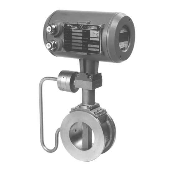
- Page 1 4/2001 Vortex flowmeter Installation and operating Instructions VFM 5090 (I)
-
Page 2: Table Of Contents
Contents Part A System installation and Start-up Description Installation in the pipeline General Sandwich type to DIN 19205 / ANSI Flanged type to DIN 2501 / ANSI B16.5 (SCH-40) Temperature and Pressure measurements 2.4.1 Temperature measurement 2.4.2 Pressure measurement with built-in sensor 2.4.3 Pressure measurement by external means Electrical connection... - Page 3 Description of program functions Numerical order description 6.1.1 Program function description 25-39 6.1.2 Program function description for AGA supported software Functional order description 6.2.1 Physical units 40-41 6.2.2 Numerical format 6.2.3 Display 6.2.4 Flow range and meter size 6.2.5 Primary information 6.2.6 Application information 6.2.7...
-
Page 4: System Installation And Start-Up
Part A System installation and Start-up Max. allowable difference between inside Description diameters of primary head and pipeline. KHRONE MARSHALL Vortex Flowmeter SIZE SIZE operate on the Karman vortex street principle to measure volumetric flow rate of gases / steam and liquids. - Page 5 INLET OUTLET Pipeline along a wall Where possible, the distance between the pipe centerline and wall should be greater than 0.5 m(20”). If it is less, first connect all cables to terminals in the connection compartment (power supply and outputs) and run them via an intermediate connection box (see also Section 3) before installing the flowmeter.
- Page 6 Sandwich Version Flanged Version...
-
Page 7: Sandwich Type To Din19205 / Ansi
Sandwich type to DIN19205 / ANSI 2.3 Flanged type to DIN 2501/ANSI B 16.5(SCH40) · · Meter sizes DN 10S, 10, 15, 20, 25, 40, 50, 80 100, Meter sizes DN 25, 40, 50, 80,100 and 150 (1”to 150 and 200 (3/8”S to 8”) 6”) ·... -
Page 8: Pressure Measurement With Built-In Sensor
· The rotating design of the housing makes it easier 2.4.2 Pressure measurement with built-in sensor to connect the two cables for power and outputs to the terminals in the rear terminal box. VFM 5090(I) may be supplied with an optional pressure sensor. -
Page 9: Outputs
3.3 Outputs 3.3.1 Abbreviations Programming Description Abbreviation Stands for via Fct. No... See Sect..Electronic counter Electro-mechanical counter Frequency (Pulse) output 1.4.X 6.1 + 6.2.9 Pulses for Q = 100 % flow rate or pulse value 1.4.2 6.1 + 6.2.9 100% Current (analog) output 1.3.X... -
Page 10: Connection Diagram For Outputs J To M
3.3.3 Frequency (pulse) output F · The frequency output is galvanically isolated from all input and output circuits but not from current output I. Therefore only one grounded receiver instrument may be connected to either frequency output F or current output ·... -
Page 11: Start-Up
3. Frequency output F: Diagram F1 in Section 6.2.9 R1 & R2 when electronic counter is connected to terminals 4/4.1/4.2 connection diagram l R1 = 1 Kohm , 1W R2 needed only for totalizer with input voltage Umax < 30 Volts. Umax 24 V 12 V... -
Page 12: Signal Converter Vfc 090
Part B Signal Converter VFC 090 5. Operation of the signal converter 5.1 General 5.1.1 Starting up signal converter When power is switched ON to signal convertor it displays TEST, VFM 5090 & Ver x.xx and then goes to measurement mode. In this initial sequence VFM 5090(I) carries out self diagnostics to check its own functional elements and loads the configuration data from non-volatile memory. -
Page 13: Operating Elements
The operating elements are accessible after 5.2 Operating elements removing the cover of the electronics section using the special wrench. CAUTION Do not damage screw thread, never allow dirt to accumulate, and make sure it is well greased at all times. ... -
Page 14: Program Organization And Programming Chart
Program organization & programming chart 5.3.1 Menu Levels The program for the signal converter consists of 5 levels. The 1 line of display will identify the menu level during programming. * Function 4.0 is not accessible in usual manner and is explicitly generated due to errors detected by one or more plausibility checks, refer Sect 5.6... -
Page 15: Programming Chart
5.3.2 Programming chart Fct 3.2.2 as NO ENTRY.CODE.1 MEASURED Fct 1.0 Fct 1.1.0 Fct 1.1.1 TO Actual 1.1.X PARAMETER OPERATION BASIS PARAM Fct 1.1.4 FUNCTIONS CODE 1(9 keys) Password - - - n Err Fct 1.2.0 Fct 1.2.1 TO Actual 1.2.X Error Msg Fct 3.2.2 as YES DISPLAY... -
Page 16: Description Of Keys
5.3.3 Description of keys Measuring mode level Main menu level Submenu level Function level Data level é é é é display measured Go to main menu Go to submenu Go to Function Units/Options è è parameters /error Enter main menu Enter submenu messages... -
Page 17: Programming And Function Of Keys
5.4 Programming and function of keys Function of keys in measurement mode : After power - on, the signal converter enters the normal measuring mode. Display shows the actual measured value of the parameter, units and arrow markers to identify parameter. A steady (non - blinking) display indicates that there are no errors in measuring mode. - Page 18 Notes When you use è to move cursor and all digits start flashing then it means that you are at the decimal point position. At this time use of é moves decimal point across the number. Usually digits cycle through 0-9 values. At certain relevant position they cycle through 0, 1, 2, . . . 9, -/E for -ve number or exponent notation.
-
Page 19: Error Messages
5.5 Error messages 5.5.1 Error messages in measurement mode Error message Type Description Corrective action required (display 2 line) INTL.ERR.nn Internal error in converter Switch off the power and try again. If the problems operation persists contact KHRONE MARSHALL service. NO SIGNAL No signal from the vortex No flow through the primary or Vortex sensor... -
Page 20: Error Messages In Programming Mode
LINE.INTR Mains power This error is generated only when totalizer is on to instrument was interrupted. indicate that internal totalizer could not totalize flow during period of the power failure. Acknowledge & reset the error by keying in E é è This text is displayed for a wide variety of errors and most of them are Fatal in nature. -
Page 21: Options Available With Vfm5090(I)
5.7 Options available with VFM5090(I) 5.7.1 METER TYPE 1. Heat Meter VFM-5090(I), supports thermal power and energy calculations for Steam and Water. Thermal power is calculated on line from the mass flow and specific enthalpy, at the operating P&T and thermal energy is calculated by time integrating (totalizing) thermal power. - Page 22 Heat vale of the mixture can be displayed in one of the following units - KJ/m3, MJ/m3, GJ/m3, BTU/ft3, BTU/in3, KCal/m3 The thermal power can be displayed in one of the following units - KJ/hr, MJ/hr, GJ/hr, BTU/hr, KCal/hr, KW and MW. Corresponding units for energy display are - KJ, MJ, GJ, BTU, KCal, KWh and MWh.
-
Page 23: Output Type
5.7.2 OUTPUT TYPE 1. RS-232 OUTPUT The RS-232 output option provides a means for communication of measured values to remote system. At present, this communication is in one direction only [from VFM 5090(I) to remote system]. Measured values as well as Error Messages which appear on the instrument display in the normal measurement mode are output on RS-232 line. - Page 24 where, Measured Value Numeric value of measured parameter as displayed in numeric field. <SP> ASCII space character. unit Unit of the measured value. <CR> <LF> ASCII carriage return and line-feed sequence. #nn Err# nn is the number of errors detected by the instrument. error mesg.
- Page 25 2.3 FORMAT Format for transmitting Measured values or Error messages is as follows : If there are no Fatal Errors detected by 5090(I) : :QV<QVval><sp><sp><QVunits><sp><sp> :QN<QNval><sp><sp><QNunits><sp><sp> :QM<QMval><sp><sp><QMunits><sp><sp> :TV<TVval><sp><sp><TVunits><sp><sp> :TN<TNval><sp><sp><TNunits><sp><sp> :TM<TMval><sp><sp><TMunits><sp><sp> :PR<PRval><sp><sp><PRunits><sp><sp> :TR<TRval><sp><sp><TRunits><sp><sp> :VE<VEval><sp><sp><VEunits><sp><sp> :FR<FRval><sp><sp><FRunits><sp><sp> :TP<TPval><sp><sp><TPunits><sp><sp> :TE<TEval><sp><sp><TEunits><sp><sp> :QF<QFval><sp><sp><QFunits><sp><sp> :XT<XTval><sp><sp><XTunits><sp><sp> :XP<XPval><sp><sp><XPunits><sp><sp> :NP<NPval><sp><sp><NPunits><sp><sp> :NE<NEval><sp><sp><NEunits><sp><sp>...
- Page 26 XT units Unit of external temperature XP val Numeric value of computed external thermal power. XP units Unit of external thermal power. NP val Numeric value of computed net thermal power. NP units Unit of net thermal power. NE val Numeric value of computed net thermal energy.
- Page 27 Example - :QM1234.56 <sp> <sp>kg/hr <sp> <sp> :TM1000.00<sp><sp>kg<sp><sp> :PR1.00<sp><sp>atm<sp><sp> :TR100.0<sp><sp>Deg.C<CR><lf> :HE# 1 Err# <sp> <sp> LOW FLOW <cr> <lf> Note that the actual number of characters in each format is not fixed and depends on the contents of Measured Value, unit and error mesg. fields. The user system may use the 2 space characters and CR, LF characters as delimiters for fields.
-
Page 28: Description Of Program Functions
Fct. 1.1.2 MAX.FLOW maximum flow rate Description of program functions Enter the maximum flow rate desired. Max. flow Numerical order description should be within the measuring range for the given primary data (3.1.x functions) and application data 6.1.1 Program function description (3.5.x functions). - Page 29 Fct. 1.1.4 TIMECONST. time constant for flow rate Fct. 1.2.2 TOTAL.UNITS totalizer unit for display Enter a low-pass filter time constant in seconds to be Totalized flow may be displayed in one of the applied to flow rate. A value of zero indicates that following units.
- Page 30 error output if any error(s) are present in the Fct. 1.2.5 VELO. UNITS velocity unit for display instrument. Range options are listed below. You can choose one of the following l 0-20 l 4-20 l 0-20/22=E l 4-20/22=E l 4-20/2=E l m/Sec l ft/Sec NO DISPLAY...
- Page 31 Fct. 1.3.6 0/4 mA POWER Enter the power value at which you want current For volumetric flow - output at its minimum 0 mA or 4 mA. l PULSE/hr l PULSE/min l PULSE/sec LIMITS : No limits l PULSE/m3 l PULS/Litre l PULS/ft3 l PULS/cft l PULS/cuft...
- Page 32 Place current meter in series with current loop then Fct. 1.4.5 F.S. POWER Enter full scale power value at which you want to select one of the following values. l 0 mA l 2 mA l 4 mA have max. frequency programmed. l 10 mA l 20 mA l 22 mA...
- Page 33 Fct. 3.1.0 BASIS.PARAM Select the language of your choice. Remember that the selection will have effect when one leaves menu This submenu function allows the user to enter the and respond with YES to save changes. vortex primary sensor data viz. nominal diameter and LIMITS - Not applicable k-factor APPEARS - Always.
- Page 34 To reset totalizer - Select RESET then select RESET LIMITS temp_low_opr temp_high_phy. YES as a double confirmation. temp_low_opr is temperature value entered in Fct. 3.3.1 TEMP.LOW. To set totalizer - Select SET then enter the value LIMITS - Setting limits 0 to 1,000,000 APPEARS - Always.
- Page 35 Fct. 3.5.1 FLUID fluid type Fct. 3.5.3 SAT. P/T use saturation P or T Select whether process medium is Steam, Gas For saturated steam only one of the operating (including air), Mixture of gases, Moist gas or Liquid. temperature or pressure is needed for density calculation.
- Page 36 l Lb/cft diameter, fluid, medium and density. Where density depends on temp. operating for all mediums except LIMITS - 0.6 to 100Kg/m -NONE- Flow computations - When temp. sensor is not APPEARS - If fluid is GAS and medium is NONE - present, value given here is used in flow computations for all mediums except -NONE- Temperature value Fct.
- Page 37 APPEARS - if Fct. 3.6.2 P-SENSOR is YES and Fct. 3.6.2 P-SENSOR pressure sensor fluid is not LIQUID. Select YES if pressure sensor option is present else select NO. Fct. 3.7.3 P12 V12 calibration point 2 at T1 LIMITS - Not applicable. Enter pressure value (same unit assumed as in Fct.
- Page 38 Thermal power may be displayed in one of the Fct. 3.8.6 NT.PWR UNITS Net thermal power following units. units. Thermal power can be displayed in any one of the following units. l KJ/hr l MJ/hr l GJ/hr — KJ/hr — BTU/hr —...
- Page 39 Fct.3.8.10 EXT.TEMP.UNIT.External temperature Fct 3.9.0 FAD PARA display unit. This submenu level has functions which allow user to This selects unit to display temperature of the external program all operating data for FAD application. temperature sensor. The options available are APPEARS - If meter type is FAD meter.
- Page 40 Fct. 3.9.4 PRES. FDROP Filter Pressure drop Fct. 4.0 PARAM.ERROR Parameter Error menu level appears if parameter Enter value of pressure drop across the filter at the check fails in the plausibility tests. There are no inlet of the compressor. (If there is no such filter submenus under this level.
- Page 41 directly corresponds to max. flow. If flow rate Fct. 4.3 PRES.OPR operating pressure exceeds max. flow an error condition ( HIGH FLOW) is generated which may affect current Enter the mean (average) operating pressure of the output depending on programming of Fct. 1.3.2 medium.
-
Page 42: Program Function Description For Aga Supported Software
APPEARS - if max. flow Fct. 1.1.2 MAX.FLOW is Assume max. flow (Fct. 1.1.2) = 1000 Kg/hr then outside the measuring range of the instrument. range f = 10000 pulses/hr (at max. flow) and Metering range is computed by sizing the range f = 10 pulses/Kg are identical. -
Page 43: Functional Order Description
l BTU / ft 3 l BTU / in3 l KCal / m3 l FAD.cft/hr l FAD.cft/min l FAD.cft/sec LIMITS - Not applicable For normalized volumetric flow - l Norm.m3/ hr l Norm.m3/ min l Norm.m3/ sec APPEARS – Always l Norm.Litre/ hr l l Norm.Litre/sec Norm.Litre/ min... - Page 44 PRESSURE UNITS DENSITY UNITS Refer to functions - Refer to function - Fct. 3.3.3. PRES. LOW pressure low limit Fct. 3.5.8 DENS. OPR.. density at operating Fct. 3.3.4 PRES. HIGH pressure high limit P&T Fct. 3.5.7 PRES. OPR operating pressure Fct.
-
Page 45: Numerical Format
6.2.2 Numerical format · Display of numerical values Real (i.e. fractional) values are displayed in the first line of the display consisting of 8 digits. Number is displayed in floating point format as far as possible, otherwise an exponent notation is used. See examples below. Floating format : 1234.5678, 100.00 Exponent format : 1234E-10, 12345E12 In most practical applications, it is very rare that parameters need be displayed in exponent format. -
Page 46: Flow Range And Meter Size
6.2.4 Flow range and meter size Flow rate (min. flow to max. flow) which the flowmeter will be able to measure depends on the primary data (3.1.x functions) and application data (3.5.x functions). thus, the flow range specified under the Fct. 1.1.2 MAX. FLOW and Fct. -
Page 47: Current (Analog) Output I
6.2.8 Current (analog) output I Current output gives an analog representation of the flow rate, power and net power also. Programming of current output is provided by 1.3.X functions. Fct. 1.3.1 FUNCTION I current output function Choose YES to make current output active as per functions Fct. 1.3.2 to Fct. 1.3.4. NO makes current output inactive (0 mA). - Page 48 Frequency output value is directly proportional to the flow rate, power and net power. Programming of frequency output value is provided by 1.4 functions. Fct. 1.4.1 FUNCTION F frequency output Choose YES -to make frequency output active as per functions Fct. 1.4.2 to Fct. 1.4.3. NO makes frequency output inactive (0 Hz).
-
Page 49: Languages Of Display Text
Frequency output proportional to any of flow, power and net power is available. This facility is available only if meter type is Heat meter or Net Heat meter. Fct. 1.4.5. F.S. POWER and Fct. 1.4.6 F.S. FREQ This defines the relationship between frequency output and power for Heat meter and Net Heat meter. Refer diagrame F-1 and sect. -
Page 50: Functional Checks
Part C Function Checks and Trouble Shooting hints Re-assemble converter in the reverse order Functional checks 7.1.2 Temperature Sensor This section describes some functional checks which can be performed without using any special PT-1000 temperature sensor can be checked by equipment. -
Page 51: Display Check
pressure sensor, temperature sensor and vortex 7.2.2 Display check sensor respectively. Remove screws D using a screwdriver for Display functionality can be checked by the use of Philips- head screws [size 2, blade length 200 Fct. 2.1 TEST DISP. mm (8”) ] and carefully remove the complete electronics. - Page 52 flow in the pipe. The additional CHECK INSTALL error (flow rate = 0.0 or some steady or fluctuating value) is an indication of : · · improper / inadequate earthing Vortex signal is falsified due to a bi-phase medium. Bi-phase media are not permitted. Use a ·...
-
Page 53: Description Of The System
Part D VFM 5090(I) Ex Description of the system The compact version of Vortex Flow meter VFM 5090(I) is suitable for operation in potentially hazardous area. The Ex version is housed in a Flameproof PDC enclosure approved by PTB. The complete instrument is designed in protection categories : EEx d[ib] IIC T2..T6 &... - Page 54 Make sure that precautions as mentioned above, are taken as Important and observe the sequence as follows: Use special wrench to remove window cover. Remove screws A to fold Display assembly to one side. Remove signal cables from latched connectors Y,Z,X (2,3,5 pin) on Barrier board assembly.
-
Page 56: Nameplates Of Vfm 5090(I)Ex
13. Nameplates of VFM 5090(I)Ex... - Page 57 The purchaser is solely responsible for the suitability in accordance with the technical regulations and Part E Technical Data applicability of our instruments Range Limits for gases -based on air at T = 0 deg C, p = 1.013 bar abs (14.69 psia) and density = 1.29 kg/m3 (0.081lbs/ft3) Meter size Inside diameter (di) Vmin...
- Page 58 Range Limits for saturated steam Flowrate Qm in Kg/hr for different (P) and density r Inside P = 1Kg/cm2_ g P = 3.5 Kg/cm2_ g P =5.2 Kg/cm2_ g P = 7 Kg/cm2_ g P = 10.5 Kg/cm2_ g P = 14 Kg/cm2_ g P = 17.5 Kg/cm2_ P = 20 Kg/cm2_ g Dia(di) r=1.12482 Kg/m3 r=2.39175 Kg/m3 r=3.22667 Kg/m3 r=4.10067 Kg/m3 r=5.78855 Kg/m3 r=7.47056 Kg/m3 r=9.15131 Kg/m3 r=10.3542 Kg/m3 3.94 18.89...
- Page 59 Range Limits for saturated steam Flowrate Qm in lbs/hr for different (P) and density r Inside P =15 PSIG P =50 PSIG P =75 PSIG P =100 PSIG P =150 PSIG P =200 PSIG P =250 PSIG P =300 PSIG Dia(di) r=0.072lbs/ft3 r=0.1498 lbs/ft3...
- Page 60 Range limit Calculation for Gases To obtain the operating density r at the operating temperature and pressure the following equation is used : ´ ´ where rn, rx = density of the gas at normal and operating conditions respectively. Pn, Px = pressure of the gas in absolute units at normal and operating conditions respectively.
- Page 61 Flowmeter (Primary head/Sensor VFS 5090(I)) Versions and meter sizes Pressure ratings see Table “Dimensions” on page 64 (Note the operating limits to DIN 2401 and ANSI B 16.5!) Sandwich design to... DIN 19205 DN 25 to 150 ANSI 1” to 6” Flange connections to ...
- Page 62 Pressure loss Dp at normal conditions See Diagram I for air (1.013 bar/0°C/rn = 1.29 kg/m (14.69psi / 32°F /rn = 0.0805 lbs /ft See Diagram II for water (20°C/ rn = 998.2 kg/m (68°F /rn = 62.31 lbs /ft at operating conditions pressure loss in Pa for gases and liquids...
- Page 63 Diagram III Min. flow velocity at various densities for gases & saturated steam. Curve Meter Size (DIN/ANSI) DN 10 S / 3/8 ” S DN 10 / 3/8 ” DN 15 / 1/2 ” DN 20 / 3/4 ” Density kg/m3 Density kg/m3 DN10S(3/8"S) TO DN20(3/4") DN25(1") TO DN200(8")
- Page 64 Signal Converter VFC 090 Full scale range programmable in litres, m , US/UK gallons, kg, tonnes, lbs, cub ft or standard flow rate per second, minute or hour 240/220/200/120/110/100 V AC + 10% Power Supply - 15% } 48 to 63 Hz 230 V AC + 6% - 10%...
- Page 65 Pulse width Frequency f = F (at q = 100%) Load rating of active output 100% Load current Load 500 ms 0.0028 Hz < f £ 1 Hz £ ³ 200 ms 0.0028 Hz 2 Hz < f £ £ ³...
- Page 66 DIMENSION DETAILS...
- Page 67 DIMENSION DETAILS :- Flanged ver. DN 80 to DN150 (3" & 6") For EX Version 204(8.03") 156(6.14") 240mm(9.45") 186mm(7.32") PG 16 Flanged ver. DN200 ( 8") For EX Version 156(6.14") 204(8.03") 240mm(9.45") PG 16 186mm(7.32") Small Size DN10s TO DN20 (3/8"s TO 3/4") 204(8.03") 156(6.14") For EX Version...
- Page 68 Dimensions and weights · Flange connections to DIN 2501 and ANSI B16.5 (Schedule 40) · Sandwich design to DIN 19205 and ANSI · Groove joint to DIN 2512 and ANSI, dimensions on request Dimension ‘a’ without gaskets between flowmeter and pipe flanges. Gaskets not included with flowmeter. High temperature version with “raised”...
- Page 69 Dimensions and weights (continued) : - Flanged version Dimensions in mm/inches Approximate weight Meter size Pr.rating DN:mm With pr.sensor Without of flanges With pr.sensor ANSI:inches pr.sensor inch inch inch inch inch DN25 PN40 28.5 1.12 9.84 13.43 14.38 7.23 12.9 14.7 DN25 PN100...
- Page 70 Dimensions in mm/inches Meter size Approximate weight Pressure rating With pr.sensor DIN:mm of flanges Without pr.sensor With pr.sensor ANSI:inches inch inch inch inch inch inch DN10S DN10,PN40 0.35 23.9 13.95 5.98 9.06 18.9 11.57 25.51 12.37 27.28 DN10,PN100 0.35 23.9 13.95 5.98 9.06...
- Page 71 Measuring principle The Vortex flowmeter is used for measuring the flow velocity of fluids in pipelines. The measuring principle is based on the development of a Karman vortex shedding street in the wake of body built into the pipeline. In theory, this process enables measurements to be carried out in turbulent flows with a Reynolds number Re >...
- Page 72 Pipe for U/S, D/S Assembly Note : 1. Material : C.S. seamless Pipe (ASTM A106 GR-B) Unless specified dimentions are in mm...
- Page 73 R/F Flanges for U/S, D/S Assembly ANSI SW Note : Flanges as per the B16.5 Surface finish 32 to 63 um. Details to be stamped * Manufacturers Name or trademark * Flange Size * Flange Pressure Class * Material Designation * Heat Code Material : C.S., SA 516 Gr.
- Page 74 Recess Flanges for U/S, D/S Assembly ANSI, SW Note : Flanges Mating Dimentions as per ANSI B16.5 Surface finish 32 to 63 um. Details to be stamped * Manufacturers Name or trademark * Flange Size * Flange Pressure Class * Material Designation * Heat Code How to Stamp * Flange Recess Facing away operator...
- Page 75 R/F Flanges for U/S, D/S Assembly DIN Note : Flanges as per DIN 2501, Surface finish 32 to 63 um., Details to be stamped * Manufacturers Name or trademark * Flange Size * Flange Pressure Class * Material Designation * Heat Code How to Stamp * Flanges Facing operator Material : C.S.
- Page 76 Recess Flanges for U/S, D/S Assembly DIN, SW Note : Flange Mating Dimentions as per DIN 2501, Surface finish 32 to 63 um., Details to be stamped * Manufacturers Name or trademark * Flange Size * Flange Pressure Class * Material Designation * Heat Code How to Stamp * Flanges Recess Facing away operator...
- Page 77 Up Stream & Down Stream Assembly for SW Note : * One set of U/S Assly. and one set of D/S Assly is to be supplied * To be painted with heat resistant paint. * Flanges to welded off center. * Welding std.- Ad-Merkblatt B8 Material : C.S.
- Page 78 End Connection JIS Flanges for U/S, D/S pipes for SW VFM Note : Flanges as per JIS B2210 Surface finish 32 to 63 um. Details to be stamped * Manufacturers Name or trademark * Flange Size * Flange Pressure Class * Material Designation * Heat Code How to Stamp...
- Page 79 U/S, D/S pipe Assly. with JIS 10K & ANSI Flanges Note : * One set of U/S Assly. and one set of D/S Assly is to be supplied * To be painted with heat resistant paint. * Flanges to welded off center. * Welding std.- Ad-Merkblatt B8 Material : C.S.
- Page 80 Note : · 150 LBS AND 300 LBS PIPE METER MATING FLANGES WITH 7D&5D LOCATING PIPES · 1" AND 1.5" METER MATING FLANGES WILL 300LBS ONLY BUT PIPE MATING FLANGES CAN BE 150LBS/300LBS · Face to face distance for DN 100/4" units is 80 mm , so one to one replacement with the old design in this case is not possible.
- Page 81 Krohne Marshall Ltd. A -34 / 35 MIDC, 'H' Blk, Pimpri, Pune 411 018 Tel : 91 (0) 20-7470171 Fax : 91 (0) 20-7477049 After Office Hrs: 020-7477762 Subject to change without notice...
Need help?
Do you have a question about the VFM 5090 I and is the answer not in the manual?
Questions and answers