Table of Contents
Advertisement
Quick Links
Instructions
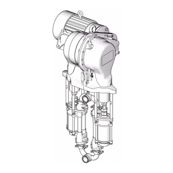
15H886 Gear Reducer
Replacement Kit
To replace the gear reducer assembly on E-Flo
Pumps.
Important Safety Instructions
Read all warnings and instructions in this manual
and in E-Flo Plus Repair-Parts manual 311594.
Save these instructions.
Graco Inc. P.O. Box 1441 Minneapolis, MN 55440-1441
Copyright 2007, Graco Inc. is registered to I.S. EN ISO 9001
311615 rev.A
™
Plus Electric Circulation
ti8317a
Advertisement
Table of Contents

Subscribe to Our Youtube Channel
Related Manuals for Graco 15H886


Summary of Contents for Graco 15H886
- Page 1 Important Safety Instructions Read all warnings and instructions in this manual and in E-Flo Plus Repair-Parts manual 311594. Save these instructions. ti8317a Graco Inc. P.O. Box 1441 Minneapolis, MN 55440-1441 Copyright 2007, Graco Inc. is registered to I.S. EN ISO 9001...
-
Page 2: Pressure Relief Procedure
Pressure Relief Procedure Pressure Relief Kit Parts Procedure Gear Reducer Kit 15H886 includes parts to replace the entire gear reducer. Parts included in the kit are marked with an asterisk, for example (5*). Use all the new parts in the kit. -
Page 3: Kit Installation
Kit Installation Kit Installation 5. Place a clean rag over the top of the slider cylinder (2) to prevent debris from falling into the slider assembly during disassembly. Disassembly 6. Place a 3/4 in. wrench on the slider piston (9) flats (just above the coupling nut), to keep the slider pis- ton/connecting rod from turning when you are loos- ening the coupling nut (14). - Page 4 Kit Installation 9. See F . 3. Rotate the crank arm (4) to allow it to be 20. Unscrew the locknuts (15) from the tie rods (3). removed from the output shaft (OS). Remove the entire fluid section. Unscrew the tie rods (3) from the gear housing.
- Page 5 Kit Installation Torque to 50-60 ft-lb (68-80 N•m). Torque to 75-80 ft-lb (102-108 N•m). Torque to 15-20 ft-lb (21-27 N•m). Torque to 66-78 in-lb (7.4-8.8 N•m). Apply antiseize lubricant to screw (5) threads. Torque key-side screw to 210-230 ft-lb (283-310 N•m) first, then torque gap side screw to 210-230 ft-lb (283-310 N•m). Apply lithium grease.
- Page 6 If installing an IEC 112M/B5 Frame electric motor The kit includes a motor coupler (28a) for a NEMA which is not supplied by Graco, ensure that the motor 184 TC Frame electric motor. shaft key cannot move out of position. If the key works...
- Page 7 Kit Installation 9. Position the crank arm (4) to engage the output 16. On pumps with the sensor circuit: shaft (OS), and rotate it to the bottom of the output a. Remove the plug from the TDC sensor port at shaft.
-
Page 8: Graco Standard Warranty
With the exception of any special, extended, or limited warranty published by Graco, Graco will, for a period of twelve months from the date of sale, repair or replace any part of the equipment determined by Graco to be defective.
Need help?
Do you have a question about the 15H886 and is the answer not in the manual?
Questions and answers