Graco Husky 15120 Series Repair Parts
Air-operated diaphragm pump
Hide thumbs
Also See for Husky 15120 Series:
- Repair parts (34 pages) ,
- Repair parts (34 pages) ,
- Operation manual (24 pages)
Table of Contents
Advertisement
Quick Links
Repair/Parts
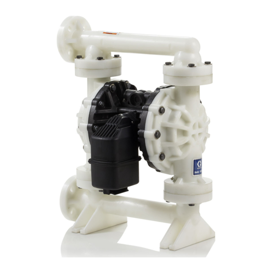
Husky™ 15120 Air-Operated
Diaphragm Pump
Polypropylene or PVDF pumps for fluid transfer applications, including high viscosity materials. For
professional use only.
Not for use in European explosive atmosphere locations.
Important Safety Instructions
Read all warnings and instructions in this manual.
Save these instructions.
Maximum Working Pressure: 125 psi
(0.86 MPa, 8.6 bar)
PROVEN QUALITY. LEADING TECHNOLOGY.
3A2889A
EN
Advertisement
Table of Contents

Subscribe to Our Youtube Channel
Related Manuals for Graco Husky 15120 Series


Summary of Contents for Graco Husky 15120 Series
- Page 1 Repair/Parts Husky™ 15120 Air-Operated 3A2889A Diaphragm Pump Polypropylene or PVDF pumps for fluid transfer applications, including high viscosity materials. For professional use only. Not for use in European explosive atmosphere locations. Important Safety Instructions Read all warnings and instructions in this manual. Save these instructions.
-
Page 2: Table Of Contents
Torque Instructions ..........19 Configuration Number Matrix ....... 7 Parts..............20 Troubleshooting..........8 Accessories............31 Notes..............10 Technical Data ........... 32 Repair..............11 Graco Standard Husky Pump Warranty....34 Pressure Relief Procedure......11 Replace Complete Air Valve ......11 3A2889A... -
Page 3: Warnings
Warnings Warnings The following warnings are for the setup, use, grounding, maintenance, and repair of this equipment. The exclamation point symbol alerts you to a general warning and the hazard symbols refer to procedure-specific risks. When these symbols appear in the body of this manual or on warning labels, refer back to these Warnings. - Page 4 Warnings WARNING EQUIPMENT MISUSE HAZARD Misuse can cause death or serious injury. • Do not operate the unit when fatigued or under the influence of drugs or alcohol. • Do not exceed the maximum working pressure or temperature rating of the lowest rated system component.
- Page 5 Warnings WARNING TOXIC FLUID OR FUMES HAZARD Toxic fluids or fumes can cause serious injury or death if splashed in the eyes or on skin, inhaled, or swallowed. • Read MSDSs to know the specific hazards of the fluids you are using. •...
-
Page 6: Ordering Information
Refer to the main Parts illustration and to the To Order Replacement Parts Parts/Kits Quick Reference. Follow the page references on these two pages for further Please call your distributor. ordering information, as needed. 3. Please call Graco Customer Service to order. Related Manuals Manual Title Number 3A2888... -
Page 7: Configuration Number Matrix
PART NO. CONFIGURATION NO. SERIAL NO. DATE CODE SERIES MAX WPR PSI-bar MADE IN Graco Inc., P.O. Box 1441 Mpls, MN 55440 USA 15120P-P01AP1PPPTFKPT Sample Configuration Number: 15120P P01A PT FK Pump Model Center... -
Page 8: Troubleshooting
Troubleshooting Troubleshooting Problem Cause Solution Pump cycles but will not prime. Reduce air inlet pressure. Pump is running too fast, causing cavitation before prime. Check valve ball severely worn or Replace ball and seat. wedged in seat or manifold. Seat severely worn. Replace ball and seat. - Page 9 Troubleshooting Problem Cause Solution Air bubbles in fluid. Suction line is loose. Tighten. Diaphragm (or backup) ruptured. Replace. Loose manifolds, damaged seats or Tighten manifold bolts or replace o-rings. seats or o-rings. Pump cavitation. Reduce pump speed or suction lift. Loose diaphragm shaft bolt.
-
Page 10: Notes
Notes Notes 3A2889A... -
Page 11: Repair
Repair Repair Pressure Relief Procedure 4. Align the new air valve gasket (105*) on the center housing, then attach the new air valve. Follow the Torque Instructions, page Follow the Pressure Relief Procedure whenever you see this symbol. 5. Reconnect the air line to the motor. This equipment stays pressurized until pressure is relieved manually. -
Page 12: Replace Seals Or Rebuild Air Valve
NOTE: Apply lithium-based grease when instructed 6. Install a retaining ring (210‡) on each end to hold to grease. Order Graco PN 111920. end caps in place. 1. Use all parts in the repair kits. Clean other parts and inspect for damage. Replace as needed. - Page 13 Repair 7. Grease and install the detent assembly (203♦) into the piston. Install the o-ring (214♦) on the cup (213♦). Apply a light film of grease to the outside surface of the o-ring and the inside mating surface of the base (212♦). Orient the end of the base that has a magnet toward the end of the cup that has the larger cutout.
-
Page 14: Check Valve Repair
Repair Check Valve Repair NOTE: Kits are available for new check valve balls and seats in a range of materials. See page 27 to order kits in the material(s) desired. O-ring and fastener kits also are available. NOTE: To ensure proper seating of the check balls, always replace the seats when replacing the balls. -
Page 15: Diaphragm And Center Section Repair
Repair Diaphragm and Center Section Repair 4. All Other Diaphragms a. Orient the pump so one of the fluid covers faces up. Use a 17 mm socket wrench to remove the fluid cover screws (5, 6), then pull NOTE: Diaphragm kits are available in a range of the fluid cover (2) up off the pump. - Page 16 Repair Reassemble the Diaphragm and Center Section Follow all notes in the illustration. These notes e. Grease the shaft u-cups (106*) and the contain important information. length and ends of the diaphragm shaft (108*). Slide the shaft into the housing. NOTE: Apply lithium-based grease whenever Reattach one fluid cover (3).
- Page 17 Repair SP and FK Models PO Models PT Models Rounded side faces diaphragm Apply lithium based grease. Apply primer and medium-strength (blue) thread locker. Torque to 65-70 ft-lb (88–95 N•m). AIR SIDE markings on diaphragm must face center housing. If screw comes loose or is replaced, apply permanent (red) thread locker to diaphragm side threads.
- Page 18 Repair 8. To ensure proper seating and extend diaphragm c. Supply a minimum of 20 psi (0.14 MPa, 1.4 life, apply air pressure to the pump prior to bar) air pressure to the air valve. Shop air attaching the second fluid cover. may be used.
-
Page 19: Torque Instructions
Torque Instructions Torque Instructions If fluid cover or manifold fasteners have been Inlet and Outlet Manifold Screws loosened, it is important to torque them using the following procedure to improve sealing. NOTE: Fluid cover and manifold fasteners have a thread-locking adhesive patch applied to the threads. If this patch is excessively worn, the fasteners may loosen during operation. -
Page 20: Parts
Parts Parts 3A2889A... - Page 21 Parts Parts/Kits Quick Reference Use this table as a quick reference for parts/kits. Go to the pages indicated in the table for a full description of kit contents. Ref. Part/Kit Description Qty. Ref. Part/Kit Description Qty. – — — Center Section; 24W212 O-RING, seat;...
- Page 22 Parts Center Section Sample Configuration Number Pump Center Fluid Seats Balls Diaphragms Seat and Model Section and Covers and Manifold Air Valve Manifolds Seal P01A 15120P Description Description HOUSING, center, not sold 108* SHAFT, center separately 109* CARTRIDGE, pilot receiver see page 24 VALVE, air, 110*...
- Page 23 Parts Sample Configuration Number Pump Center Fluid Seats Balls Diaphragms Seat and Model Section and Covers and Manifold Manifolds Air Valve Seal P01A 15120P Center Section Rebuild Kits (*) Center Shaft Kits (*) P01A with 2–Piece diaphragms (PT) 24W206 P01A with 2–Piece diaphragms (PT) 24W208 or standard diaphragms...
- Page 24 Parts Air Valve Sample Configuration Number Pump Center Fluid Seats Balls Diaphragms Seat and Model Section and Covers and Manifold Air Valve Manifolds Seal P01A 15120P Description Description HOUSING, not sold 208✦✝ U-CUP separately 209✦✝ SCREW, #4, thread forming 202✦ PISTON 210‡...
- Page 25 Parts Sample Configuration Number Pump Center Fluid Seats Balls Diaphragms Seat and Model Section and Covers and Manifold Manifolds Air Valve Seal P01A 15120P ✝ Air Valve Seals Kit Air Valve Replacement Kit All models 24B769 All models 24B773 Kit includes: Kits include: •...
- Page 26 Parts Fluid Covers and Manifolds Sample Configuration Number Pump Center Fluid Seats Balls Diaphragms Seat and Model Covers and Section and Manifold Air Valve Manifolds Seal 15120P P01A Fluid Cover Kits End Inlet Manifold Kits Polypropylene PVDF Polypropylene PVDF 24W210 24W216 24W215 24W266...
- Page 27 Parts Seats and Check Balls Sample Configuration Number Pump Center Fluid Seats Balls Diaphragms Seat and Model Covers and Section and Manifold Air Valve Manifolds Seal 15120P P01A Seat Kits Ball Kits 24W225 24W230 24W227 24W228 24W229 24W226 24W223 Kits include: Kits include: •...
- Page 28 Parts Diaphragms Sample Configuration Number Pump Center Fluid Seats Balls Diaphragms Seat and Model Section and Covers and Manifold Manifolds Air Valve Seal 15120P P01A 1–Piece Bolt-Through Overmolded Diaphragm Kit Diaphragm Kits 24W217 24W218 Kits include: 24W219 • 2 overmolded diaphragms (12), material indicated Kits include: in table.
- Page 29 Parts Sample Configuration Number Pump Center Fluid Seats Balls Diaphragms Seat and Model Section and Covers and Manifold Manifolds Air Valve Seal 15120P P01A 2-Piece Bolt-Through Fluid Plate Kits Diaphragm Kit P1, P2 24W221 24W220 24W222 Kits include: Kits include: •...
- Page 30 Parts Manifold Seals Sample Configuration Number Pump Center Fluid Seats Balls Diaphragms Seat and Model Covers and Section and Manifold Air Valve Manifolds Seal 15120P P01A Manifold O-Ring Kits All Models 24W212 Kits include: • 8 o-rings (9), PTFE 3A2889A...
-
Page 31: Accessories
Accessories Accessories Muffler 111897 Legacy or remote exhaust muffler option. NOTE: See DataTrak Manual 313840 for: • Pulse Count Conversion Kit 24B794 • DataTrak Conversion Kits 24B784 • All other data monitoring parts, including reed switches and solenoids. Replacement Air Valve Kit 24B774, Polypropylene, DataTrak Compatible Kit includes nuts, valve, and gasket. -
Page 32: Technical Data
Technical Data Technical Data Husky 15120 Diaphragm Pump Metric Maximum fluid working pressure 125 psi 0.86 MPa, 8.6 bar Air pressure operating range 20 to 125 psi 0.14 to 0.86 MPa, 1.4 to 8.6 bar Air inlet size 1/2 in. (npt(f) Air exhaust size 1 in. - Page 33 Technical Data Maximum pump speed 1–piece bolt-through diaphragms 192 cycles per minute 2–piece bolt-through diaphragms 183 cycles per minute Overmolded diaphragms 195 cycles per minute Weight Polypropylene 57 lb 25.9 kg PVDF 74 lb 33.6 kg Wetted Parts Wetted parts include material(s) chosen for seat, ball, and diaphragm options, plus the pump’s material of construction: Polypropylene or PVDF Non-wetted external parts stainless steel, polypropylene...
-
Page 34: Graco Standard Husky Pump Warranty
With the exception of any special, extended, or limited warranty published by Graco, Graco will, for a period of five years from the date of sale, repair or replace any part of the equipment determined by Graco to be defective. This warranty applies only when the equipment is installed, operated and maintained in accordance with Graco’s written recommendations.
Need help?
Do you have a question about the Husky 15120 Series and is the answer not in the manual?
Questions and answers