Salus Optima S User Manual
Hide thumbs
Also See for Optima S:
- User manual (44 pages) ,
- Setup manual (2 pages) ,
- Installation manual (2 pages)

Subscribe to Our Youtube Channel
Related Manuals for Salus Optima S


Summary of Contents for Salus Optima S
- Page 1 Optima S & Optima SR Thermostat User Guide For other language versions, please visit: www.salusinc.com...
- Page 2 An authorized, qualified installer may be required. • Do not connect any of the terminals to the 110/220 VAC supply. The Optima S Thermostat uses two AA batteries or a 24 VAC power source. • Do not cover any of the vents on the thermostat.
-
Page 3: Table Of Contents
Optima S Thermostat ONTENTS INTRODUCTION INSTALLING THE THERMOSTAT CONTROLS AND DISPLAY UTTONS NDICATORS INITITALIZATION CONFIGURING THE THERMOSTAT AVIGATING THE ETTINGS ETTINGS EQUIPMENT TYPE REVERSING VALVE FAN CONTROL AUXILARY RELAY FUNCTION AUXILARY RELAY ACTIVATION TEMPERATURE SENSOR SELECT INTERNAL TEMPERATURE SENSOR OFFSET... - Page 4 Salus DELTA ND STAGE HEATING DELTA ST STAGE COOLING DELTA ND STAGE COOLING COMPRESSOR PROTECTION MIN OFF TIME FAN DELAY HEAT MAX SET POINT COOL MIN SET POINT DEADBAND HEAT PROTECTION LOCK KEYPAD SOURCE LOCK LEYPAD FUNCTION DISPLAY UNITS DEGREES...
- Page 5 JOIN NETWORK JOIN NEW NETWORK FACTORY RESET THE HOME SCREEN CHANGING THE SET POINT TEMPERATURE FAN CONTROL OPERATING MODE LOCKING UNLOCKING THE KEYPAD SCHEDULE FUNCTION TEMPORARY HOLD PERMANENT HOLD PAIRING OPTIMA S WITH SS909ZB TEMPERATURE SENSOR SPECIFICATIONS TROUBLESHOOTING SALUS WARRANTY...
-
Page 6: Salus
Salus APPENDIX A – WIRING DIAGRAMS ERMINAL EFINITIONS ONVENTIONAL INGLE RANSFORMER EAT AND YSTEM ONVENTIONAL RANSFORMER EAT AND YSTEM LOOR EATING YSTEM INGLE RANSFORMER YSTEM RANSFORMER YSTEM APPENDIX B – REGULATORY STATEMENTS FCC S TATEMENTS NDUSTRY ANADA NDUSTRY ANADA... -
Page 7: Introduction
Optima S Thermostat NTRODUCTION The Optima S is available in 2 configurations: Standard and Router to the network. Model Description ST898ZB This model functions as a standard ‘End Device’ and may be powered by 24VAC or battery. SA898ZBR This model functions as a Router to the network and will route messages between devices on the network. -
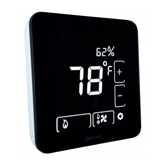
Page 8: Controls And Display
ONTROLS AND ISPLAY Buttons There are six (6) button areas on the Optima S touchscreen display as shown on the right and defined below. The Reset button is a recessed button on the bottom side surface of the device, below the logo. -
Page 9: Indicators
Optima S Thermostat Indicators The following indicators are available on the LCD display. Message Display Humidity Display Low Battery Time Display Main Temperature Display Confirm Icon Increment Icon Permanent Hold Status Icon Cancel Icon Decrement Icon Network Icon Fan Status... - Page 10 Salus Indicator Description Message Display Alphanumeric display of HVAC status and labels Time Display Displays time in 12- or 24-hour format if provided by the network Main Temperature Displays the room temperature or set point as required Display Permanent Hold...
-
Page 11: Inititalization
If the thermostat had previously joined a network, it will default to the Home screen. Once initialization is complete, the Optima S is ready for use, or to be configured for the intended application. The Optima S may be configured manually through the keypad, or by using the SALUS Smart Home App. -
Page 12: Configuring The Thermostat
Salus ONFIGURING THE HERMOSTAT There is an extensive list of configuration settings that can be accessed by tapping the Settings button. Navigating the Settings Menu To move forward and back through the Settings menu and make any changes to the... -
Page 13: Equipment Type
Optima S Thermostat The thermostat defaults to a Heat Pump equipment type with configuration settings typical for that type of equipment. Equipment Type allows you to select the equipment the Optima S will be controlling. (default) For conventional Heat Pumps EQPT TYP- Use the + or –... -
Page 14: Auxilary Relay Activation
The remote sensor, SS909ZB, may be paired with the thermostat and the value will be displayed on the Optima S. The Settings menu allows you to select the internal or external sensor for control. -
Page 15: Delta 1 St Stage Heating
Optima S Thermostat Depending on the Equipment Type selected, you may have 2 heating stages and 2 cooling stages. The parameters below allow you to set the separation between when the 1 stage energizes, and the 2 stage energizes below set point (heating) and above set point (cooling). -
Page 16: Heat Max Set Point
Salus The heating and cooling set points may be set to a limited range to prevent over heating or under cooling a space to save energy. • HEAT MAX SETPT does not appear if EQPT TYP is AC only •... -
Page 17: Lock Keypad Source
Optima S Thermostat The LOCK SRC determines if the key lock function can be controlled by the thermostat keypad (hold + and - buttons for 3+ seconds) and the App, or just by the App (default) Key Lock Source Use the + or – buttons to switch between values. -
Page 18: Display Units ( Degrees )
Salus Temperature values may be displayed in degrees F or in C. °C C/F Selection Use the + or – buttons to switch between ºF DEGREE UNITS °F (default) and ºC The display brightness may be adjusted from 1 (dim) to 10 (brightest). Increasing display brightness will impact battery life. -
Page 19: Show / Hide Humidity Reading
Optima S Thermostat The Optima S has an internal humidity sensor which is displayed by default. If you do not wish to see the humidity value, you can choose to hide the humidity reading. (default) Show or hide humidity Use the + or – buttons to switch between Show... -
Page 20: Set Schedule
Salus (default) Current schedule mode: After OTA, if there is no schedule mode in EDIT- WKDY/WKND Press √ to edit schedule. the device side and it has joined network, WEEKLY DAILY Press + or – to step through then schedule mode is CLOUD, device... -
Page 21: Join New Network
A hardware reset will not clear configuration and network settings. CREEN The Optima S home screen provides offers basic functions using the Home Screen controls Time and Date or current operating mode Humidity value (if selected) -
Page 22: Changing The Set Point Temperature
Salus Changing the Set Point Temperature To change the set point, simply touch the Up (+) or Down (+) button. The ambient temperature will move to the time display area and the current set point will be displayed in the Main Temperature display. The Message Display will indicate which set point is being changed. -
Page 23: Operating Mode
Optima S Thermostat Operating Mode To change the operating mode of the system, simply touch the Mode button to select between the following: • – The thermostat will not call for heat or cooling. • Cool – The thermostat will call for cooling if the room temperature is above the Cool set point. -
Page 24: Schedule Function
Salus Schedule Function The Optima S includes a flexible programmable schedule to vary set points based on time of day to reduce energy when there is an opportunity to relax the comfort level. While the schedule can be set using the keypad, it is more efficient to use the App. -
Page 25: Temporary Hold
Optima S Thermostat Tap the Settings button to edit the Schedule Interval 1 Tap + or – button to select a different Interval Interval # will flash button to move to edit time Tap + or – to increase or decrease the time... -
Page 26: Permanent Hold
The current set point will be maintained until a future change is made, or The Permanent Hold is turned Off by selecting a Schedule mode. Pairing Optima S with SS909ZB Temperature Sensor When the thermostat is located where it may not read the optimum temperature for the comfort zone, a remote wireless sensor (SS909ZB) may be paired with the thermostat and the ambient temperature of the remote sensor will be used for control. - Page 27 Optima S Thermostat If the SS909ZB had previously joined the network, but is not paired with the Optima S: Place the Optima S in Identify mode (step 2 above). Place the SS909ZB in pairing mode: Hold the network button on the side of the sensor for 3 seconds until the LED...
-
Page 28: Specifications
Salus PECIFICATIONS Temperature units °C or °F Operating temperature 32-122 °F (0-50 °C) Indoor temperature 32-104 °F (0-40 °C) measurement range Protocol ZigBee – Home Automation 1.0 AC power 18-30 VAC at RC and C terminals Battery Power * 2 x AA Alkaline batteries... -
Page 29: Troubleshooting
Optima S Thermostat ROUBLESHOOTING The thermostat does not call for heat and/or cooling. • Check that the connector pins are straight. • Check that the thermostat is fully seated on the mounting plate. If the terminal connections are not fully engaged, the firmware does not activate the relays. -
Page 30: Salus Warranty
ALUS ARRANTY SALUS North America, Inc. (“Salus”) warrants that for a period of two (2) years (“Warranty Period”) from the date of purchase by the consumer (“Customer”), this device, excluding batteries (“Product”), shall be free of defects in materials and workmanship under normal use and service in accordance with all supplied instructions. - Page 31 Optima S Thermostat No oral or written information or advice given by Salus or a Salus-authorized representative shall modify or extend this warranty. If any term is held to be illegal or unenforceable, the legality or enforceability of the remaining terms shall not be affected or impaired.
- Page 32 Salus A – W PPENDIX IRING IAGRAMS Terminal Definitions Optima S Thermostat Terminal Reference Terminal Non-Heat Pump Heat Pump Power Jumper (RH) 24 VAC for Cooling System or Jumper to RJP 24 VAC for Heating System 24 VAC for Heat Pump...
- Page 33 Optima S Thermostat Conventional Single Transformer Heat and Cool System RJ P J umper Wire AC_IN Transformer POWER SUPPLY Line 18-30 VAC Volt age AC_IN Y1 Relay Cooling Y2 Relay Cooling W1 Relay Heat ing W2 Relay Heat ing Fan Relay...
- Page 34 Salus Conventional Two Transformer Heat and Cool System RJ P Transformer AC_IN Line 18-30 VAC POWER Volt age SUPPLY AC_IN Y1 Relay Cooling Y2 Relay Heat ing Transformer Cooling W1 Relay Heat ing 18-30 VAC Line Volt age W2 Relay...
- Page 35 Optima S Thermostat Floor Heating System RJ P J umper Wire AC_IN Transformer POWER SUPPLY Line 18-30 VAC Volt age AC_IN Y1 Relay Y2 Relay W1 Relay Floor Heat ing W2 Relay Fan Relay...
- Page 36 Salus Single Transformer Heat Pump System RJ P J umper Wire AC_IN Transformer POWER SUPPLY Line 18-30 VAC Volt age AC_IN Y1 Relay Compressor Y2 Relay Compressor W1 Relay Auxiliary Heat ing W2 Relay Changeover Valve Fan Relay M CU...
- Page 37 Optima S Thermostat Two Transformer Heat Pump System RJ P Transformer AC_IN Line 18-30 VAC POWER Volt age SUPPLY AC_IN Y1 Relay Compressor Y2 Relay Heat ing Transformer Compressor W1 Relay 18-30 Auxiliary Heat ing Line Volt age W2 Relay...
- Page 38 Salus B – R PPENDIX EGULATORY TATEMENTS FCC Statements WARNING: Changes or modifications to this unit not expressly approved by the party responsible for compliance could void the user’s authority to operate the equipment. This device complies with Part 15 of the FCC Rules. Operation is subject to the following...
- Page 39 Optima S Thermostat FCC and Industry Canada RF Radiation Exposure statement: This equipment complies with FCC and Industry Canada RF radiation exposure limits set forth for an uncontrolled environment. This equipment should be installed and operated with a minimum distance of 20 centimeters between the antenna and all persons.
- Page 40 For Sales assistance: sales@salusinc.com For technical support: support@salusinc.com SALUS North America, Inc. 2215 Cornell Avenue Montgomery, IL 60538 SMC-UG-ST898ZB/ZBR-EN-202208v1 Copyright © SALUS North America, Inc. 2022...
Need help?
Do you have a question about the Optima S and is the answer not in the manual?
Questions and answers