Salus RT310RF Full User Manual
Hide thumbs
Also See for RT310RF:
- Quick start manual ,
- Installation manual (15 pages) ,
- Full user manual (20 pages)
Table of Contents
Advertisement
Advertisement
Table of Contents

Related Manuals for Salus RT310RF


Summary of Contents for Salus RT310RF
- Page 1 RT310RF THERMOSTAT - FULL USER MANUAL...
-
Page 2: Table Of Contents
TABLE OF CONTENTS 1. Introduction ................................4 1.1 Product Compliance ..................................4 1.2 Safety Informations ..................................4 2. Product Overview ...............................5 2.1 Package content ....................................6 2.2 Proper thermostat location ................................6 2.3 Wall mounting ....................................7 2.4 Free-standing device ..................................7 3. Before you start (first power up) ..........................8 3.1 LCD icon description ..................................8 3.2 Button description ..................................8 3.3 First power up sequence and configuration ...........................9... -
Page 4: Introduction
1. Introduction 1.1 Product Compliance This product complies with the essential requirements and other relevant provisions of Directives 2014/53/EU and 2011/65/EU. The full text of the EU Declaration of Conformity is available at the following internet address: www.saluslegal.com. 1.2 Safety Informations •... -
Page 5: Product Overview
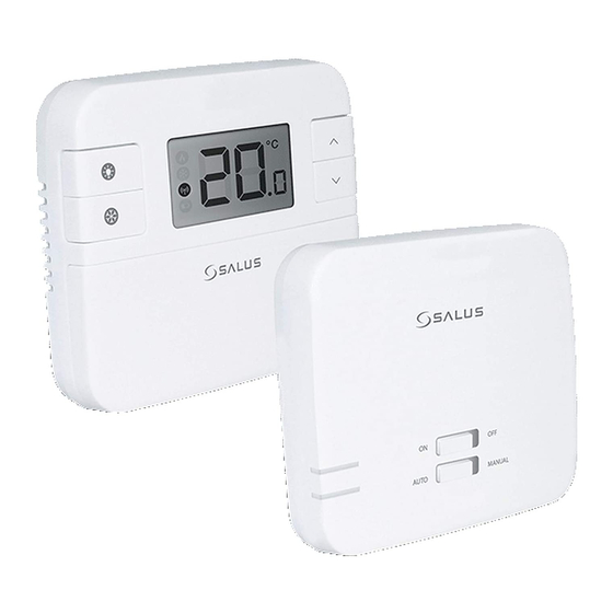
2. Product Overview The RT310 room thermostat simply switches the heating system on and off as necessary. It works by sensing the air temperature, switching on the heating when the air temperature falls below the thermostat setting, and switching it off once this set temperature has been reached. Turning a room thermostat to a higher setting will not make the room heat up any faster. -
Page 6: Package Content
2.1 Package content 1) RT310TX thermostat 2) RXRT510 receiver 3) Mounting bracket 4) 2x AA batteries 5) Short instruction 6) Mounting screws 2.2 Proper thermostat location Please note: The ideal position to thermostat mounting is about 1,5m under floor level far from heating or cooling sources. Thermostat can’t be exposed to sunlight or any extreme conditions like for example draft. -
Page 7: Wall Mounting
2.3 Wall mounting How to mount the thermostat to the wall: Fix the backplate Align the front housing Fit the front housing. at the top edge Press lightly. to the wall. 2.4 Free-standing device Thermostat can be used as a free-standing device (without need of wall mounting). Use a bracket included with the set as shown at the picture:... -
Page 8: Before You Start (First Power Up)
4. Low battery status 2. Cooling Mode */Frost protection 5. Temperature unit mode indication 6. Room / setpoint temperature 3. RF signal indicator (only in RT310RF) 3.2 Button description 1. Turn on the LCD backlight 4. Increase button 2. HEAT/COOL * modes change 5. -
Page 9: First Power Up Sequence And Configuration
3.3 First power up sequence and configuration To power up the thermostat you have to put the batteries inside. Then thermostat will display following sequence: Remove the protection foil and insert After that, thermostat will 2xAA batteries by removing front automatically power up and it will cover. -
Page 10: Rxrt510 Receiver
4. RXRT510 receiver The thermostat communicates wirelessly with the RXRT510 receiver. The receiver should be supplied with 230VAC, the maximum load of the receiver is 16A. Avoid installing the device in places directly exposed to water, moisture and air condensation. The RXRT510 receiver can operate in two different modes - AUTO (automatic) and MANUAL (manual). -
Page 11: Led Indications In The Receiver
4.2 LED indications in the receiver The status of the RXRT510 receiver is indicated by two LEDs. These are LEDs with the following colors: - red (upper one), - green (lower one). A detailed explanation of the meaning of the LEDs can be found in the table below: Wyjaśnienie The receiver is connected to the 230V power supply and is paired with the thermostat. -
Page 12: Wall Mounting Of The Receiver
4.3 Wall mounting of the receiver Wall mounting the receiver: drill two ø6 mm holes in the wall. Insert the plugs and, by putting the plate to the wall (included in the set), put the two screws through the holes and then screw them in. Connect the necessary cables to the receiver. Next, hang the receiver on the board using the handles designed in the receiver, marked in the picture below. -
Page 13: Connection Description
RXRT510 RXRT510 16 (5) A 4.4 Connection description AC 230V AC 230V RT310TX RXRT510 RXRT 2 x AA AC 230V AC 230V RT310TX RXRT510 RXRT510 16 (5) A 2 x AA C 230V AC 230V RT310TX RXRT510 RXRT510 2 x AA 16 (5) A RT310TX 2 x AA... -
Page 14: User Settings
5. User settings 5.1 Manual mode - changing temperature setpoint In manual mode, the thermostat maintains a constant temperature set by the user. To set temperature setpoint follow steps below: Press to set the new First, thermostat is displaying actual temperature setpoint. -
Page 15: Frost Protection Mode
5.2 Frost protection mode In this mode the setpoint temperature is automatically set to frost setpoint to prevent pipes from freezing. If the room temperature is lower than the frost setpoint, frost protection will be enabled. To set frost protection mode follow steps below: Press button to turn Snowflake icon will be displayed if... -
Page 16: Heat/Cool Mode
5.4 Heat/Cool mode * User can set thermostat for heating or cooling. In HEAT mode thermostat is displaying flame icon all the time. When thermostat is in HEAT mode and thermostat is CALLING for HEAT – the flame icon is flashing. In COOL mode thermostat is displaying snowflake icon all the time. When thermostat is switched to the COOLING mode and the thermostat is CALLING for COOL –... -
Page 17: Temperatures Outside Operating Range
5.5 Temperatures outside operating range Temperatures below 10 °C are displayed without the leading ‘0’ . Temperatures exceeding the measurable range will be indicated by ‘HI’ for temperatures above the upper limit, and ‘LO’ for temperatures below the lower limit, as shown in the images. 5.6 Low battery detection Battery voltage is checked every minute. -
Page 18: Installer Mode
6. Installer mode To enter installer parameters please follow steps below. Please refer to parameters table description before any changes. Use button to move through parameters. Use for adjustements. Every change/selection confirm by button. 3 sec 3 sec 3 sec Press and hold button to move through simultanously for about 3 seconds to... -
Page 19: Rt310Tx Thermostat Pairing With The Receiver
The word PAIRING in the user settings means the function of synchronizing the transmitter with the receiver again, if it has been removed. WARNING! IN THE SET RT310RF THE THERMOSTAT IS FACTORY PAIRED WITH THE RECEIVER! In order to pair the devices correctly, you must first prepare the receiver for synchronization! -
Page 20: Test The Pairing Process
Receiver will go back to normal work to return to the main screen. mode. If you purchased an RXRT510 or RT310TX and intend pairing with other devices in the 5x5 range, please refer to the Receiver Units manual or the relevant manuals available at www.salus-controls.eu... -
Page 21: Reset Function
9. Reset function To RESET RT310TX thermostat please follow steps below: When you want to change the batteries your device will use the internal memory to backup your settings. You have 30 seconds to TEST / PAIRING change the batteries before losing −... -
Page 22: Cleaning And Maintenance
10. Cleaning and Maintenance The RT310RF thermostat requires no special maintenance. Periodically, the outer casing can be wiped clean using a dry cloth (please DO NOT use solvents, polishes, detergents or abrasive cleaners, as these can damage the thermostat). There are no user serviceable parts within the unit; any servicing or repairs could only be carried out by Salus Controls or their appointed agents. -
Page 23: Warranty
12. Warranty SALUS CONTROLS warrants this product to be free from any defects in material or workmanship and to perform as specified for a period of five years from the date of installation. SALUS CONTROLS reserves the sole responsibility for breach of this warranty by repairing or replacing the defective product. This product includes software that matches the distributor’s identification at the time of sale. - Page 24 SALUS Controls is a member of the Computime Group. Maintaining a policy of continuous product development SALUS Controls plc reserve the right to change specification, design and materials of products listed in this brochure without prior notice. Ver. 5 Issued: 23 XII 2020 Soft version: 2.1...
Need help?
Do you have a question about the RT310RF and is the answer not in the manual?
Questions and answers