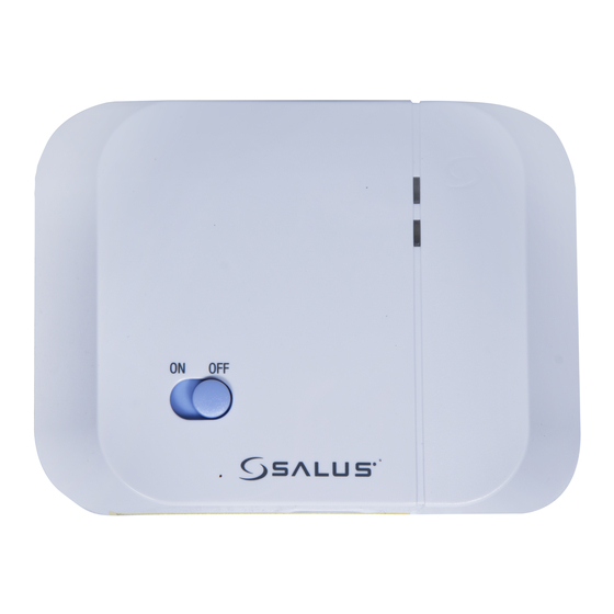
Salus RXRT505 Instruction Manual

Salus RXRT505 Instruction Manual

Thermostat receiver units
Hide thumbs Also See for RXRT505:

Advertisement

RT
RT
RT
RT
RT5
RT
RT5
RT5
RT5
RT5
RT5
RT
RT5
RT5
RT5
T
T
T
T
T
T
T
T
T
T
T
T
T
T
T
T
T
T
T
T
T
T
T
T
T
T
T
T
T
T
T
T
T
T
T
T
T
T
T
T
T
T
T
T
T
T
T
T
5
5
5
5
5
5
5
5
5
5
5
5
5
5
5
5
5
5
5
0 0
0
0
0
0
0
0
0
0
0
0
0
0
05RF
5 R
5
5
R
R
R
R
R
R
R
R
F
F
F
F
F
F
F
F
F
R
R
R
R
R
R
R
R
T
T
T505RF
T5
T
T505RF
T
T5
T
T
T
0
0
0
0
0
0
5
5
5
5
5
R
R F
R
R
R
R F
This instruction manual covers the receivers above
F
F
F
R
R
R
R
R
RT
RT50
R
R
T
T
50
5
0
0
0
0
0
5R
5RF
RXRT505
RXVBC605
Thermostat Receiver Units
R
R
R
R
F
F
F
R
R
R T
R
R
R
R
R
R
R
R
R
R
R
R
R
R
R
R
R
R
R
R
R
R
R
R
T
T50
T
T
T
T
T505RF
T
T
T
T
T
T
5
5
5
5
5
5
5
5
5
5
5
5
5
5
0
5
5
5
5
5
5
5
5RF
5
5
5
5
5
5
5
5
5
5
R
R
R
R
R
R
R
R
R
R
R
R
R
R
R
R
R
R
R
R
F
F
F
F
RXST625
RXWBC605
886MHz

Advertisement

Table of Contents
loading

Summary of Contents for Salus RXRT505

  • Page 1 05RF T505RF T505RF Thermostat Receiver Units RT50 T505RF RXST625 RXRT505 RXWBC605 RXVBC605 This instruction manual covers the receivers above 886MHz...
  • Page 2: Various Models

    ST625TX RT505TX 0915FLTX 0915FLT ST325TX RT305TX SUPPLIED SEPERATELY...
  • Page 3 RXRT505 RXVBC605 RXWBC605...
  • Page 4: Safety Information

    • Low Voltage Directive 2006/95/EEC • EC Marking directive 93/68/EEC SAFETY INFORMATION These instructions are applicable to the Salus Controls model stated on the front cover of this manual only, and must not be used with any other make or model. These instructions are intended to apply in the United Kingdom only, and should be followed along with any other statutory obligations.
  • Page 5: Connecting

    RT RECEIVER INTRODUCTION The RXRT505 is used for the wiring connections and on/off control. The RXRT505 is linked to your thermostat via radio frequency (RF) signal. Features • LED status indication • ON / OFF switch • 868 MHz communication...
  • Page 6: Receiver Wiring Terminals

    N terminals. The COM and NO is FEED to be connected to the boilers external loop (see diagram Thermostat loop (Remove link) below), if connected in this way Live Feed the receiver relay can only switch voltage supplied by the boiler. RXRT505 INSTRUCTION MANUAL...
  • Page 7: Setting Up Rf Communication

    3. When the red LED on the receiver stops flashing, pairing has been successful. * For full instructions on thermostat pairing see: RT505TX Manual - Page 13 ST325TX Manual - Page 15 RT305TX Manual - Page 9 ST625TX Manual - Page 11 RXRT505 INSTRUCTION MANUAL...
  • Page 8 S-SERIES RECEIVERS INTRODUCTION The RXST625 is used for the wiring connections and on/off control. The RXST625 is linked to your thermostat via radio frequency (RF) signal. Features • LED status indication • Manual override • 868 MHz communication CONNECTING THE RXST625 RECEIVER The RT receiver should be mounted in a suitable location that is both accessible for the connection of mains and control wiring, and allows good reception of the RF signal.
  • Page 9 TYPICAL WIRING INSTALLATIONS The RXST625 receiver is wired the BOILER same way no matter if you are RECEIVER wirings 240V or 24V, the receiver will always need a 240V Live and COM N/O Neutral feed connected into L & N MAINS terminals.
  • Page 10 RECEIVER LED INDICATORS The LED indicators on the RXST625 receiver are designed to give a clear and easily understood indication of the current state of the system. The various LED signal combinations and descriptions of what they indicate are shown in the table below: State Indication Blue...
  • Page 11: User Control Function Summary

    The status of the RXST625 receiver is indicated by the use of two bi- colour Light Emitting Diodes (LEDs). The status indicators are: USER CONTROL FUNCTION SUMMARY Key/Operation Functions Auto Sets receiver to Automatic mode (default setting) Manual Sets receiver to Manual mode Turns relay output ON (default setting) Cycle Switches receiver output on and off in a 15 minute cycle...
  • Page 12: Manual Mode

    MANUAL MODE Moving the slide switch to the ‘MANUAL’ position selects the manual operation mode of the RF receiver. In manual mode, the receiver ignores the RF signal from the thermostat and controls the output relay manually, based on the setting of the failsafe mode switch. FAILSAFE MODES Failsafe mode has three user selectable settings –...
  • Page 13 Installing the RF boiler control takes minutes. Once installed, you will benefit from all the control features of the Salus room thermostat. INTEGRAL RF BOILER CONTROL The Integral RF boiler control is the RF receiving unit for your RF room thermostat.
  • Page 14 Mounting the RF Integral Boiler Control to the boiler DANGER! • 24V & 230V: Do not Touch Electrical Components or circuits • Isolate mains electricity supply before starting any work and observe all relevant safety precautions. • Follow electro static discharge precaution. Do not touch any visible PCB parts or components.
  • Page 15 Before switching the boiler on at its mains supply, ensure the module switch is in the OFF position. To ensure the boiler control is connected properly, please now move the switch to ON The boiler should now go on and the LED on the your boiler control should illuminate.
  • Page 16 SETTING UP RF COMMUNICATION WITH YOUR THERMOSTAT Ensure the switch on the RF integral boiler module is in the AUTO Gently press and hold the SYNC button with a blunt object. After 3 seconds the Boiler Control LED will flash once every second to indicate it is ready to pair and ready to receive a signal from the...
  • Page 17 USER CONTROLS Integral RF Boiler Control A – LED This LED will be on when the thermostat is demanding heat. B – Mode Switch ON – Boiler will be on continuous AUTO – will follow instructions from the thermostat OFF – Boiler is off C –...
  • Page 18 Installing the RF boiler control takes minutes. Once installed, you will benefit from all the control features of the Salus thermostat. INTEGRAL RF BOILER CONTROL The Integral RF boiler control is the RF receiving unit for your thermostat.
  • Page 19 RF Transmission The receiving range between your thermostat and the RF Boiler Control is around 100 metres in open air, however many factors can affect the RF transmission and shorten the operating distance, e.g. shielding by thick walls, foil back plasterboard, metal objects such as filing cabinets, general RF interference, and so on.
  • Page 20 4. First plug in the connector block C ensuring correct orientation. Remember to ensure the block is fully connected. 5. Now locate the boiler control’s four hooks then press in and down. Replace Cover panel A. 6. Replace the front fascia and boiler’s outer casing RXWBC605 INSTRUCTION MANUAL...
  • Page 21 Before switching the boiler on at its mains supply, ensure the module switch is in the OFF position To ensure the boiler control is connected properly, please now move the switch to ON . The boiler should now Fire and the LED on the your boiler control should illuminate Now move the switch back to AUTO RXWBC605 INSTRUCTION MANUAL...
  • Page 22 RF Boiler Control When the switch on the Boiler Module is in the AUTO position, the boiler control will automatically receive the RF signal from the thermostat and control the module output so that it switches the boiler accordingly. The user can also move the switch to the MANUAL ON position; when in this mode, the boiler will be always turned on and the LED indicator will also be lit constantly.
  • Page 23 USER CONTROLS Integral RF Boiler Control A – LED This LED will be on when the thermostat is demanding heat. B – Mode Switch ON – Boiler will be on continuous AUTO – will follow time and temperature program in the transmitter OFF –...
  • Page 24 TECHNICAL SPECIFICATION RXRT505 Radio Frequency (RF) Settings Operating Frequency: 868 MHz Max. Operating Range: 100 metres (open air) or 30 metres (indoors) Environment Operating Temperature: 0 ºC to + 50 ºC Storage Temperature: -20 ºC to + 60 ºC TECHNICAL SPECIFICATION RXST625...
  • Page 25 TECHNICAL SPECIFICATION RXVBC605 Radio Frequency (RF) Settings Operating Frequency: 868 MHz Max. Operating Range: 100 metres (open air) or 30 metres (indoors) Environment Operating Temperature: 0 ºC to + 50 ºC Storage Temperature: - 20 ºC to + 60 ºC TECHNICAL SPECIFICATION RXWBC605 Radio Frequency (RF) Settings Operating Frequency:...
  • Page 26 NOTES RECEIVER INSTRUCTION MANUAL...
  • Page 27 Salus Controls sole liability for breach of this warranty will be (at its option) to repair or replace the defective product.
  • Page 28 Email: sales@salus-tech.com Tel: 01226 323961 Sales Email: tech@salus-tech.com Tel: 01226 323961 Technical Salus Controls plc, Salus House, Dodworth Business Park South, Whinby Road, Dodworth, Barnsley S75 3SP...

Table of Contents