Table of Contents
Advertisement
Quick Links
Advertisement
Table of Contents

Related Manuals for Keysight 16451B


Summary of Contents for Keysight 16451B
- Page 1 Keysight E5061B Network Keysight 16451B Dielectric Test Fixture Analyzer Installation Guide This is the Installation Guide for E5061B Network Analyzer. This is the Operation and Service Manual for 16451B Dielectric Test Fixture. Operation and Service Manual...
- Page 2 EULA. governed by United States and Declaration of Conformity Keysight shall be under no obligation international copyright laws. to update, revise or otherwise modify Trademark Acknowledgments Declarations of Conformity for this the Software.
-
Page 3: Table Of Contents
16451B Overview ........ - Page 4 Bibliography .............91 Keysight 16451B Operation and Service Manual...
-
Page 5: Installation
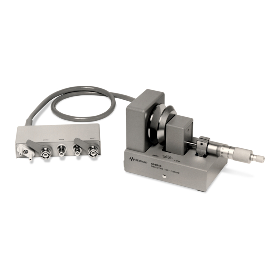
CAUTIONs, and NOTEs given throughout this document must be carefully followed to ensure the operator's safety and to not damage the 16451B. Product Description The 16451B is a Dielectric Test Fixture used with LCR meters and impedance analyzers for accurate measurement of insulating and dielectric materials. Applicable Instrument... -
Page 6: Initial Inspection
Table 1-1 of this Operation and Service Manual. 3. Inspect the exterior of the 16451B for any signs of damage. The Electrode-A (38 mm electrode) and the Unguarded electrode are installed on the test fixture when the 16451B is shipped from the factory. - Page 7 Test Fixture (with (16451-61071) Electrode A, Electrode A, Unguarded Unguarded electrode and electrode and covers) covers) 16451-60013 Electrode B and 16451-60013 Electrode B and cover cover 16451-60012 Electrode C and 16451-60012 Electrode C and cover cover Keysight 16451B Dielectric Test Fixture...
- Page 8 Hex key (for 5188-4452 Hex key (for replacing replacing electrodes) electrodes) 16451-60001 Carrying Case 16451-60001 Carrying Case The Electrode-A and the Unguarded electrode are installed on the test fixture when the 16451B is shipped from the factory. Keysight 16451B Dielectric Test Fixture...
-
Page 9: General Information
“dielectric constant” is often called “permittivity” in other documents. This manual will unify it to “dielectric constant”. Safety Considerations The 16451B conforms to the safety requirements of an IEC (International Electrotechnical Commission) Publication-348 (1971) Safety Class 1 instrument and is shipped from the factory in a safe condition. -
Page 10: Serial Number
Complimentary copies of the supplement are available from Keysight Technologies. If the serial prefix or number of a 16451B is lower than that on the title page of this manual, see Appendix A, Manual Changes. -
Page 11: Specifications
Specifications This section lists the complete 16451B specifications. These specifications are the performance standards and limits against which the 16451B is tested. When shipped from the factory, the 16451B meets the specifications listed in this section. Function Test fixture for measuring dielectric constant and dissipation factor. -
Page 12: Supplemental Performance Characteristics
[Hz] f ≤ 30MHz ε’ measured permittivity tanδ: measured dissipation factor ε permittivity of air 8.854 x 10 [F/m] diameter of electrode {A,B} [m] thickness of material [mm] Impedance measurement error of instrument Keysight 16451B Dielectric Test Fixture... - Page 13 The surfaces of material are assumed to be ideally parallel, flat and smooth. The above equation is only compatible for electrodes A and B. Permittivity Measurement Accuracy including 4294A and E4990A (Supplemental Characteristics) Figure 2-1 Electrode A, MUT Thickness: 1mm Keysight 16451B Dielectric Test Fixture...
-
Page 14: Electrode Dimensions
Electrode B, MUT Thickness: 1mm 1. OSC LEVEL: 500mV 2. BW: 5 3. ADAPTER TYPE: 4TP_1M 4. COMPENSATION: OPEN, SHORT & LOAD Electrode Dimensions Guarded/Guard Electrode (4 types, changeable) 1. For materials without applied thin film electrodes. Keysight 16451B Dielectric Test Fixture... - Page 15 General Information Supplemental Performance Characteristics Figure 2-3 Dimensions of Electrode-A Figure 2-4 Dimensions of Electrode-B Keysight 16451B Dielectric Test Fixture...
- Page 16 General Information Supplemental Performance Characteristics 2. For materials with applied thin film electrodes. Figure 2-5 Dimensions of Electrode-C Figure 2-6 Dimensions of Electrode-D Keysight 16451B Dielectric Test Fixture...
-
Page 17: Available Test Material Dimensions
Electrode-D 20 to 56 mm ≤ 10 mm 5 to 14 mm 1. Including thickness of thin film electrodes 2. As a diameter of the thin film electrode Micrometer Resolution The micrometer resolution is 10μm. Keysight 16451B Dielectric Test Fixture... -
Page 18: Dimensions Of Fixture Assembly
General Information Supplemental Performance Characteristics Dimensions of Fixture Assembly Figure 2-8 Dimensions of Test Fixture Assembly Keysight 16451B Dielectric Test Fixture... -
Page 19: Storage And Repacking
The following general instructions should be used when repacking with commercially available materials: 1. Wrap the 16451B in heavy paper or plastic. When shipping to a Keysight Technologies sales office or service center, attach a tag indicating the service required, return address, model number, and the full serial number. - Page 20 General Information Storage and Repacking Keysight 16451B Dielectric Test Fixture...
-
Page 21: Operation
Introduction This chapter describes the product overview, basic theory of measuring dielectric constant using the 16451B, methods for measuring dielectric constant step by step, details of measurement procedure basic measurement procedure summarized and typical measurement procedures. The last part of this chapter describes measurement error factors. -
Page 22: 16451B Overview
Operation 16451B Overview 16451B Overview The 16451B is a test fixture for measuring disc and film dielectric materials when connected to Keysight's LCR meters, Capacitance meters or impedance analyzers, and is usable up to 30MHz. The 16451B provides the fixture assembly, four interchangeable Guarded/Guard electrodes and accessories. - Page 23 Guarded/Guard electrode to adjust its pressure on the Unguarded electrode to be the same as when the 16451B is placed so that the surface of electrodes is perpendicular. Keysight 16451B Dielectric Test Fixture...
-
Page 24: Furnished Accessories
It has a built in clutch which will slip at a specified torque. Furnished Accessories The 16451B provides some accessories, such as 4 types of changeable electrodes and their covers, an attachment for error correction, Hex key, and Carrying case. - Page 25 Guarded electrode (2 -a) and a Guard electrode (2 -b). The diameter of guarded electrode is 5 mm. The electrode is provided with a cover (2 -c) to protect its surface. Keysight 16451B Dielectric Test Fixture...
- Page 26 Hex Key This is a hex key used to interchanging and adjust the electrodes. Carrying case This is a carrying case used to store and carry the fixture assembly and its accessories. Keysight 16451B Dielectric Test Fixture...
-
Page 27: Dielectric Measurement Basic
The dielectric constant can be obtained using the following equation. --- - C Where, Ɛ Dielectric constant (permittivity) [F/m] Ɛ Space permittivity = 8.85410 [F/m] Ɛ Relative dielectric constant (Relative permittivity) of test material Keysight 16451B Dielectric Test Fixture... -
Page 28: Guard Electrode
Figure 3-4. When the guard electrode as used by the 16451B surrounds the guarded electrode as used by the 16451B, it is possible to measure the capacitance of the test material accurately, because the guard electrode can avoid the stray capacitance at the edge of the electrode as... - Page 29 Operation Dielectric Measurement Basic Figure 3-4 Capacitance Measurement using Unguarded Electrode System Figure 3-5 Capacitance Measurement using Guarded Electrode System Keysight 16451B Dielectric Test Fixture...
-
Page 30: Measurement Method
There are many kinds of methods to measure the capacitance of a solid material. Three measurement methods are applicable to the 16451B, they are the Contacting Electrode method (Rigid Metal electrode), the Contacting Electrode method (Thin Film electrode) and the Non-Contacting Electrode method (Air Gap method). -
Page 31: Contacting Electrode Method (Used With Rigid Metal Electrode)
Figure 3-7 Contacting Electrode Method (Rigid Metal Electrode) Dielectric constant and dissipation factor of a test material can be obtained using the following equations. Parameters Needed: Equivalent parallel capacitance [F] Dissipation factor Keysight 16451B Dielectric Test Fixture... - Page 32 Dissipation factor of test material Electrode of the 16451B The 16451B provides two applicable electrodes, Electrode-A (38 mm electrode) and Electrode-B (5 mm electrode), for the Contacting Electrode method (Rigid Electrode method) to match the size of test material as shown in Figure 3-8.
- Page 33 Operation Measurement Method Figure 3-8 Electrode of the 16451B for Contacting Electrode Method (Rigid Metal Electrode) Applicable Size of Test Material for Electrode-A (38 mm Guarded/Guard Electrode) Diameter of material greater than or equal to 40 mm and smaller than or equal...
- Page 34 Applicable Size of Test Material for Electrode-B (5 mm Guarded/Guard Electrode) Diameter of material greater than or equal to 10 mm and smaller than or equal to 56 mm Thickness of material less than or equal to 10 mm Keysight 16451B Dielectric Test Fixture...
-
Page 35: Contacting Electrode Method (Used With Thin Film Electrode)
Contacting Electrode Method (used with Thin Film Electrode) This method uses thin film electrodes applied on the test material. The thin film electrodes contact with the 16451B's electrodes. This method is applicable for materials on which the thin film electrodes can be applied without changing its characteristics. - Page 36 =8.854 x 10 [F/m] Equations: r - - - - - - - - - - - - - - ------------------------------- - Keysight 16451B Dielectric Test Fixture...
- Page 37 16451B and the diameter of the thin film guard electrode must be greater than the inner diameter of the guarded electrode of the 16451B.
- Page 38 Applicable Size of Test Material for Electrode-C Applicable Size of Test Material for Electrode-D (Guarded/Guard Electrode for Small Thin Film Electrodes) Diameter of test material greater than or equal to 20 mm and less than equal to 56 mm Keysight 16451B Dielectric Test Fixture...
-
Page 39: Non-Contacting Electrode Method (Air Gap Method)
(such as foam rubber), or soft materials. The merits and demerits of this method are as follows: • Merits — Air film (error caused by air gap between the electrode and the surface of test material) does not cause error Keysight 16451B Dielectric Test Fixture... - Page 40 Dissipation factor when the test material is not inserted Gap between Guarded/Guard electrode and Unguarded electrode Series capacitance when the test material is inserted [F] Dissipation factor when the test material is inserted Average thickness of test material [m] Equations: Keysight 16451B Dielectric Test Fixture...
- Page 41 Guard electrode. Figure 3-17 Figure 3-18 show the applicable size of test materials for these electrodes. Figure 3-16 Electrode of the 16451B for Non-Contacting Electrode Method (Air Gap Method) Keysight 16451B Dielectric Test Fixture...
- Page 42 Applicable Size of Test Material for Electrode-B (5 mm Guarded/Guard Electrode) Diameter of test material greater than or equal to 10 mm and smaller than or equal to 56 mm Thickness of material less than or equal to 10 mm Keysight 16451B Dielectric Test Fixture...
- Page 43 Operation Measurement Method Figure 3-18 Applicable Size of Test Material for Electrode-B Keysight 16451B Dielectric Test Fixture...
-
Page 44: Preparation Of Test Material
Shape and Size of Test Material The applicable shape of the test material for the 16451B should be a plate or a film. The applicable size (diameter) of the test material should be greater than the inner diameter of the Guard electrode used. The 16451B can also measure test materials whose shape is not a disk, when the size of the test material is greater than the inner diameter of the Guard electrode. -
Page 45: Flatness Of Test Material's Surface
Preparation of Test Material For example, when a test material whose dielectric constant is less than 10 is measured using the 16451B with an LCR meter, the value measured is only a few pF. When small capacitance is measured, measurement error increases. To reduce the error and to obtain accurate capacitance value, the capacitance value of your test material must be in the range shown in Appendix B. -
Page 46: Connecting To The Instrument
(0.5 mm if possible). Connecting to the Instrument The 16451B can be connected directly to the measurement terminals of a 4-terminal pair configuration. Set the Cable Length switch or softkey of the instrument to 1 m to compensate for the error caused by the test leads of the 16451B. -
Page 47: Changing The Guarded/Guard Electrode
After cleaning, return the covers to protect the surface. 2. Connect the Guarded/Guard electrode and tighten the screw using a hex key. 3. Turn the small knob until it slips when the covered electrodes touch each other. Keysight 16451B Dielectric Test Fixture... - Page 48 “Electrode Adjustment” on page 54. If it happens, replace the scratched/contaminated electrode or contact your nearest Keysight Technologies Sales and Service Office. As long as the measured capacitance falls within the limits, the electrode doesn’t need to be replaced or repaired.
-
Page 49: Error Correction
Figure 3-20 Connecting the Attachment to the Guarded/Guard Electrode for OPEN correction 3. Turn the small knob of the 16451B cw (clockwise) to bring the Unguarded electrode into contact with the attachment (until the clutch slips). As shown Figure 3-21, the inner electrode of the Guarded/Guard electrode is completely surrounded by the guard. -
Page 50: Short Correction (Zero Short Offset Adjustment)
For Electrode-A and Electrode-B (Rigid Metal Electrode) When you use Electrode-A (38 mm electrode) and Electrode-B (5 mm electrode), the residual impedance contained in the 16451B can be reduced by performing the following SHORT correction procedure. 1. Turn the small knob ccw to move the Guarded/Guard electrode away from the Unguarded electrode. - Page 51 SHORT Correction for Rigid Metal Electrode 4. Perform the SHORT correction measurement. (The procedure to perform the SHORT correction depends on the measurement instrument, for the details of this procedure, refer to operation manual of the measurement instrument.) Keysight 16451B Dielectric Test Fixture...
- Page 52 When you use Electrode-C (electrode for large thin film electrodes) and Electrode-D (electrode for small thin film electrodes), the residual impedance contained in the 16451B can be reduced by performing the following SHORT correction procedure 1. Turn the small knob ccw to move the Guarded/Guard electrode away from the Unguarded electrode, then remove the cover from both electrodes.
- Page 53 C and D 1.5 pF ±0.05 pF Actual measurement procedure for the LOAD standard is as follows: Adjust the distance between the 16451B's electrodes, measure C at 100 kHz, and sets it as the LOAD compensation standard value (C : measured value and G: 0).
-
Page 54: Electrode Adjustment
It has a built-in clutch which will slip at a specified torque. Do not turn the Unguarded electrode adjustment screws cw when the Guarded/Guard electrode contacts Unguarded electrode. If you do so, the micrometer will be overloaded and break. Keysight 16451B Dielectric Test Fixture... -
Page 55: Rough Adjustment To Make Electrodes Parallel
Unguarded electrode. Use the following procedure to perform this adjustment before the measurement and after changing the electrodes. 1. Place the 16451B so that the surface of electrodes are vertical as shown in Figure 3-25. -
Page 56: Accurate Adjustment To Make Electrodes Parallel
When Electrode-A and Electrode-B are used, perform the following procedure after performing the “Rough Adjustment to Make Electrodes Parallel”. When you use Electrode-C and Electrode-D (Thin Film electrodes), you do not need to perform the rough adjustment. Keysight 16451B Dielectric Test Fixture... - Page 57 3. Connect the 16451B to an LCR meter or an impedance analyzer and select the capacitance measurement function (C ) for Circuit mode. (Refer to “Connecting to the Instrument”.) 4. Place the 16451B so that the surfaces of electrodes are vertical as shown in Figure 3-27. Figure 3-27 Vertical Position 5.
- Page 58 “Electrode Adjustment” on page 54. If it happens, replace the scratched/contaminated electrode or contact your nearest Keysight Technologies Sales and Service Office. As long as the measured capacitance falls within the limits, the electrode doesn’t need to be replaced or repaired.
- Page 59 ) for Circuit mode. (Refer to “Connecting to the Instrument”.) 4. Place the 16451B so that the surface of electrodes is vertical as shown in Figure 3-27. 5. Turn the large knob of the micrometer ccw to make enough room between the Guarded/Guard electrode and the Unguarded electrode, and then remove the cover from both electrodes.
- Page 60 (D) increases suddenly. In this case, immediately turn the screw ccw to separate the electrodes and redo adjustment. 9. Place the 16451B so that the surface of electrodes are horizontal and check that the measured capacitance value is within the limit listed in Table 3-6.
- Page 61 Operation Electrode Adjustment When the measured capacitance value is less than the limit, place the 16451B so that the surface of electrodes are Vertical. Then keep pressing Guarded/Guard pressure adjustment and carefully turn the three screws in a clockwise sequence until the measured capacitance value is within the limits in Table 3-6.
-
Page 62: Typical Measurement Procedure By The Measurement Methods
You should perform the adjustment in the same environmental conditions as you will measure the test material using the 16451B, because a change of temperature causes mechanical dimensions to change. When you change temperature condition, you should perform the accurate adjustment after temperature conditions have changed, because a change of temperature causes mechanical dimensions to change. - Page 63 Contacting Electrode Method (Thin Film Electrode) Procedure 1. Prepare test material so that the 16451B can measure it. (When you use Thin Film electrode, you should apply Thin Film electrodes on the surface of the material to be measured. For more information, refer to “Preparation of...
- Page 64 After you measure the test material (or move the electrode) several times, it is recommended that you check electrode for parallelism (refer to “Check Electrode Parallelism”) and clean the surface of electrodes. For more information on measuring accurately, refer to “Measurement Error Analysis”. Keysight 16451B Dielectric Test Fixture...
-
Page 65: Non-Contacting Electrode Method
Non-Contacting Electrode Method For the Non-Contacting method, the 16451B can perform an Air Gap method. The 16451B provides two sizes of electrodes for the Air Gap method, so you should select the electrode for the material to be tested. For more information on selecting electrodes, refer to “Measurement... - Page 66 After you measure the test material (or move the electrode) several times, it is recommended to check for electrode parallelism (refer to ““Check Electrode Parallelism”) and clean the surface of electrodes. For more information on accurate measurement, refer to “Measurement Error Analysis”. Keysight 16451B Dielectric Test Fixture...
-
Page 67: Check Electrode Parallelism
If the capacitance value is out of limits, perform the Accurate Adjustment as shown in “Accurate Adjustment to Make Electrodes Parallel”. Table 3-7 Measured Capacitance Limits for Check Electrode Parallelism Electrode Capacitance Value Electrode-A 700pF to 1000pF Electrode-B 12pF to 17pF Keysight 16451B Dielectric Test Fixture... -
Page 68: Measurement Error Analysis
1pF. (For measurement frequency range of them, refer to Table 1-2.) For more information on measurement accuracy of LCR meters, Capacitance meters and impedance analyzers, refer to their Operation Manual or Technical Data Sheet. Keysight 16451B Dielectric Test Fixture... - Page 69 This airgap effect can be eliminated, by applying a thin film electrode to the surfaces of the dielectric material. An extra step is required for material preparation (fabricating a thin film electrode), but the most accurate measurements can be performed. Keysight 16451B Dielectric Test Fixture...
- Page 70 The effective area constant represents the increase of electrode area caused by stray capacitance, and is as follows: when ε = ε a when ε > ε Keysight 16451B Dielectric Test Fixture...
- Page 71 Electrode distance [mm] 1.0105 1.0526 1.0105 1.0524 1.0105 1.0526 1.0105 1.0524 1.0105 1.0525 1.0105 1.0523 1.0105 1.0525 1.0104 1.0523 1.0105 1.0525 1.0104 1.0522 1.0105 1.0525 1.0104 1.0521 1.0105 1.0524 1.0103 1.0520 1.0104 1.0523 1.0103 1.0518 Keysight 16451B Dielectric Test Fixture...
- Page 72 1.0032 1.0230 0.06 1.0063 1.0387 1.0028 1.0203 0.05 1.0058 1.0346 1.0023 1.0173 0.04 1.0052 1.0317 1.0019 1.0140 0.03 1.0045 1.0278 1.0014 1.0106 0.02 1.0035 1.0225 1.0009 1.0071 0.01 1.0022 1.0147 1.0005 1.0035 (ϕ means diameter) Keysight 16451B Dielectric Test Fixture...
-
Page 73: Error Factor Using Non-Contacting Electrode Method
To reduce this error, measure the thickness at several points of the measured area of the test material using an accurate micrometer. Do not use the micrometer equipped with the 16451B. • Parallelism and Flatness of Electrodes and Test Materials: This error is... - Page 74 Δt can be obtained as follows: – - - - - - - 1 t set Where, Measured capacitance value [F] Keysight 16451B Dielectric Test Fixture...
- Page 75 40μm, 50μm, and 60μm. Each theoretical capacitance values and equivalent electrode distance errors are listed in Table 3-11. Table 3-11 Compensation Result Example Δt [μm] [pF] [pF] [μm] 227.60 252.48 185.20 202.11 Keysight 16451B Dielectric Test Fixture...
- Page 76 - - - - - - a C s2 Where, t is the equivalent electrode distance. For more information, refer to “Effective Area of Electrode” in “Error Factor using Contacting Electrode Method” “Gap Error”. Keysight 16451B Dielectric Test Fixture...
-
Page 77: Service
The assemblies in the 16451B are secured using metric threaded fasteners. All fasteners used in the 16451B, can be removed using medium and small pozidrive screwdrivers and a 2.5 mm hex key. A 2.5 mm hex key (Keysight PN 5188-4452) is included with the 16451B. - Page 78 The proper tightening torque is 6-7 in-lb. (About 6-7 in-lb may be applied to the screw when the furnished hex key is used.) If the screw is tighten too much, the micrometer will not function smoothly. Keysight 16451B Dielectric Test Fixture...
-
Page 79: Replaceable Part List
Parts listed in these tables can be ordered from your nearest Keysight Technologies Service office. Ordering information should include the Keysight part number and the quantity required. Once the original support part is depleted, please proceed to obtain the RoHS compliant support part. - Page 80 2190-0586 Washer 0515-0909 Screw 0515-0382 Screw with Washer 8750-0373 Micrometer 8750-0373 Micrometer 16451-04001 Cover 16451-04601 Cover 0515-0914 Screw 0515-1946 Screw 16451-00602 Plate 16451-00602 Plate 0515-0914 Screw 0515-1946 Screw 16451-24001 Unguarded 16451-24021 Unguarded (16451-24021) Electrode Electrode Keysight 16451B Dielectric Test Fixture...
- Page 81 Description Part Number Compliant Replacement Part 16451-04003 Cover Bottom 16451-04613 Cover Bottom (16451-04013) 0403-0427 Bumper Foot 0403-0427 Bumper Foot 0515-0914 Screw 0515-1946 Screw 16451-04002 Cover Top 16451-04602 Cover Top 16451-61002 Cable Assembly 16451-61072 Cable Assembly Keysight 16451B Dielectric Test Fixture...
- Page 82 1. These parts are included in the Cable Assembly 16451-61072. Table 4-3 Replaceable Parts List (3 of 5) Non-RoHS Description RoHS Compliant Description Part Number Replacement Part 16451-20002 Base 16451-20622 Base (16451-20022) 16451-25007 Spacer 16451-25007 Spacer 16451-61002 Cable Assembly 16451-61072 Cable Assembly Keysight 16451B Dielectric Test Fixture...
- Page 83 6960-0147 Plug Hole 6960-0076 Plug Hole 0515-1550 Screw 0515-0372 Screw 1. Apply a drop of Lock Tile (Keysight PN: 0470-0013) to the screws, when replacing them. Table 4-4 Replaceable Parts List (4 of 5) Non-RoHS Description RoHS Description Part Number...
- Page 84 Electrodes A and C include a 56mm Cover. Electrodes B and D include a 20mm Cover. • Electrode-A: 38mm Guarded/Guard electrode • Electrode-B: 5mm Guarded/Guard electrode • Electrode-C: Guarded/Guard electrode for large thin film electrode • Electrode-D: Guarded/Guard electrode for small thin film electrode Keysight 16451B Dielectric Test Fixture...
-
Page 85: Troubleshooting
0 to 10mm. If the electrode does not move smooth it may be because the cables are obstructing the operation. Electrical Trouble When the 16451B is electrically defective, check its cable connections, refer to Figure 4-4. The connection check points are as follows: •... - Page 86 Service Troubleshooting Figure 4-4 Cable Connection Diagram Keysight 16451B Dielectric Test Fixture...
-
Page 87: A.manual Changes
Manual Changes This appendix contains the information required to adapt this manual to earlier versions or configurations of the 16451B than the current printing date of this manual. The information is this manual applies directly to 16451B Dielectric Test Fixture whose serial number prefix is listed on the title page of this manual. -
Page 88: Changes 2
Replacement Part 16451-04013 Cover Bottom 3. Change the Part Number as follows in Table 4-3, “Replaceable Parts List (3 of 5),” on page Non-RoHS Description RoHS Description Part Number Compliant Replacement Part 16451-20022 Base Keysight 16451B Operation and Service Manual... -
Page 89: B.manual Changes
Dielectric Test Fixture Operation and Service Manual Manual Changes This section shows the recommended capacitance range of test materials for using the 16451B with Electrode-A (ϕ38 mm electrode) or Electrode-B (ϕ5 mm electrode). Using Electrode-A (ϕ38mm electrode) The area surrounded by bold lines in... -
Page 90: Using Electrode-B (Φ5Mm Electrode)
Manual Changes Using Electrode-B (ϕ5mm electrode) Using Electrode-B (ϕ5mm electrode) The area surrounded by bold lines in Figure B-2 shows the recommended capacitance range when using Electrode-B. Figure B-2 Recommended Capacitance Range Using Electrode-B Keysight 16451B Operation and Service Manual... -
Page 91: C.bibliography
Keysight 16451B Dielectric Test Fixture Operation and Service Manual Bibliography Bibliography ASTM Standards:D150-81,\Standard Test Method for A-C Loss Characteristics and Permittivity (Dielectric Constant) of Solid Electrical Insulating Materials”, Annual Book of ASTM Standards, Vol 10.02, July, 1987, pp.21-44. - Page 92 Bibliography Bibliography Keysight 16451B Operation and Service Manual...
- Page 93 Electrode-A diameter Cable Length switch Electrode-B Effective Area , 70, Capacitance Limits Electrode-C equivalent distance Capacitance measurement Electrode-D Error Analysis Error , 68, Test Material error factor , 33, 34, tolerance Flatness , 69, Keysight 16451B Operation and Service Manual...
- Page 94 Test Fixture (used with Thin Film compensation test material Electrode) Correction diameter Non-contacting Electrode , 34, 38, Flatness Method (Air Gap for Electrode-A Method) , 33, for Electrode-B , 34, Manual Change , 10, Keysight 16451B Operation and Service Manual...
- Page 95 Thin Film Electrode Tolerance trouble Electrical Trouble Mechanical Trouble Troubleshooting , 77, Typical Measurement Unguarded Electrode Unguarded electrode Vertical Position adjustment Capacitance Limit Washer , 80, 82, Weight ZERO OPEN offset ZERO SHORT offset α α Keysight 16451B Operation and Service Manual...
- Page 96 Index Keysight 16451B Operation and Service Manual...
- Page 97 This information is subject to change without notice. © Keysight Technologies 1989-2023 Edition 7, Jan 2023 *16451-90020* 16451-90020 www.keysight.com...
Need help?
Do you have a question about the 16451B and is the answer not in the manual?
Questions and answers