Table of Contents
Advertisement
Quick Links
Advertisement
Table of Contents

Related Manuals for Keysight 16047E


Summary of Contents for Keysight 16047E
- Page 1 Keysight 16047E Test Fixture Operation and Service Manual...
- Page 2 EULA. governed by United States and Declaration of Conformity Keysight shall be under no obligation international copyright laws. to update, revise or otherwise modify Trademark Acknowledgments Declarations of Conformity for this the Software.
-
Page 3: Table Of Contents
Connecting the 16047E ........ - Page 4 Contents Keysight 16047E Test Fixture...
-
Page 5: Installation Guide
Inspect the shipping container for damage. If the shipping container or cushioning material is damaged, it should be kept until the contents of the shipment have been checked for completeness and the 16047E has been checked mechanically and electrically. The contents of the shipment should be... -
Page 6: Connecting The 16047E
Follow these steps below to connect the 16047E to the instrument with screw holes. Step 1. Set the 16047E test fixture to the test connectors on the front panel of the Impedance Analyzer by gradually coupling the four BNC connectors and fastening screws of the fixture with the test connectors and accessory mounting holes of the instrument until they come to complete contact. -
Page 7: Connecting To The Instrument Without The Screw Holes
Figure 1-2 Locations of fastening screws Step 1. Set the 16047E test fixture to the UNKNOWN connectors on the instrument by gradually coupling the four BNC connectors and fastening screws of the fixture with the connectors of the instrument until they come to complete contact. -
Page 8: Cleaning
Installation Guide Cleaning Cleaning When the electrodes get dirty, their contact resistance increases resulting in inaccurate measurement. Use soft cloth to clean the electrode to remove dust particles or any other dirt. Keysight 16047E Test Fixture... -
Page 9: Overview
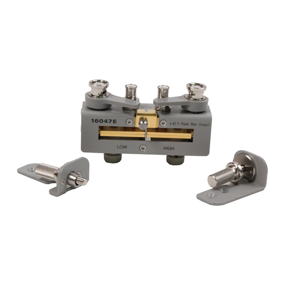
Overview Product Overview The 16047E is a test fixture used to measure parts with leads. When used with the Impedance Analyzer, the fixture provides highly accurate measurement with wide frequency range up to 120 MHz. Also it gains mechanical stability and a prolonged life when it is secured to the Impedance Analyzer with its fastening screws. -
Page 10: Functions
Overview Functions Functions Figure 2-2 shows name of each part of the 16047E and Table 2-1 shows function. Figure 2-2 16047E Parts Table 2-1 16047E Function NAME FUNCTION Electrode Contact for DUT electrode. The LOW side electrode connected to an instrument’s L and the HIGH side electrode connected to an instrument’s... -
Page 11: Operation
Performing Fixture Compensation To enhance measurement accuracy, fixture compensation should be done before DUT measurement. The fixture compensation requires measurements with the 16047E for open and short compensation data. The following procedure shows the measurement for the compensation data. Performing Open Compensation The open compensation procedure is as follows. -
Page 12: Performing Load Compensation
Do not fasten the screws too tightly to prevent the electrodes from damaged. 2. Follow the instruction manual that came with your instrument to perform a measurement to obtain load compensation data. Keysight 16047E Test Fixture... -
Page 13: Dut Measurement
2. Fasten both of the securing screws. Do not fasten the screws too tightly to prevent the electrodes from damaged. Figure 3-2 Performing DUT Measurement 3. Follow the instruction manual that came with your instrument to measure your DUT. Keysight 16047E Test Fixture... -
Page 14: Measuring 3-Terminal Device
Operation Measuring 3-terminal device Measuring 3-terminal device The 16047E allows you to measure a 3-terminal device shown in Figure 3-3. Figure 3-3 3-terminal device Use the guard terminal on the fixture to measure a 3-terminal device. Connect the lead No. 3 to the guard terminal in order to measure only characteristics of... - Page 15 Similarly, connect the lead No. 2 to the guard terminal in order to measure only characteristics of Z eliminating any effects from Z and Z Connect your device to the guard terminal with a shortest possible lead. Longer lead will degrade the guard effect resulting in less accurate measurement result. Keysight 16047E Test Fixture...
- Page 16 Operation Measuring 3-terminal device Keysight 16047E Test Fixture...
-
Page 17: Specifications And Supplemental Performance Characteristics
Keysight 16047E Test Fixture Operation and Service Manual Specifications and Supplemental Performance Characteristics This chapter provides specifications and supplemental performance characteristics of the 16047E test fixture. Specifications Applicable Instruments LCR meters and Impedance Analyzers with four-terminals Applicable DUT Type Lead components Frequency ≤... -
Page 18: Supplemental Performance Characteristics
Specifications and Supplemental Performance Characteristics Supplemental Performance Characteristics Supplemental Performance Characteristics This section provides useful data on the 16047E. These supplemental performance characteristics should not be considered specifications. Additional Error Additional errors are calculated as follows. |Z| Measurement Additional error Ze [%] of the |Z| measurement is calculated by substituting the values in the table below into the following equation. - Page 19 De = ( Ze / 100) × (1 + Dx) where Dx is the measured value of D. It is necessary for Ze to be below 10 %. D is not expressed as a percentage but as an absolute value. Keysight 16047E Test Fixture...
- Page 20 Dx is the measured value of D and is calculated as follows. Dx = 2 × π × f × Csx × Rsx, where f: measurement signal frequency Csx: measured value of Cs Rsx: measured value of Rs. Keysight 16047E Test Fixture...
-
Page 21: Service
RoHS support part backward incompatible with non-RoHS 16047E. Special handling is needed while using the RoHS replacement part on non-RoHS 16047E. The original support part number is replaced by the respective “RoHS Compliant Upper Level Assembly Replacement Part”. -
Page 22: Replaceable Parts
Service Maintenance Replaceable Parts Figure 5-1 Replaceable Parts (part 1 of 2) Keysight 16047E Test Fixture... - Page 23 16047-09001 INSULATOR 16047-60105 16047-00625 SHIELD 16047-60105 16047-24022 SCREW 16047-24022 16047-00621 SHORT BAR 16047-00621 16047-04021 COVER 16047-60105 16047-60015 BNC LEVER ASSEMBLY 16047-60105 16047-60016 CONNECTOR-BNC 16047-60105 16047-00626 CONTACT 16047-60105 16047-24023 SLEEVE (Removed) 16047-00627 PLATE (Removed) 0515-0999 SCREW 16047-60105 Keysight 16047E Test Fixture...
- Page 24 Service Maintenance Figure 5-2 Replaceable Parts (part 2 of 2) Keysight 16047E Test Fixture...
- Page 25 16047-04022 COVER 16047-04022 16047-24021 KNOB 16047-24021 16047-24026 FLANGE 16047-24026 0515-0914 SCREW 0515-1227 16047-01222 ANGLE 16047-01222 0515-0952 SCREW 0515-2151 0515-0999 SCREW 0515-1375 16047-25021 INSULATER 16047-25021 0515-2791 SCREW 16047-60105 16047-24025 SLEEVE 16047-60105 0515-0914 SCREW 0515-1227 16047-01221 ANGLE 16047-01221 Keysight 16047E Test Fixture...
- Page 26 Service Maintenance Keysight 16047E Test Fixture...
- Page 27 This information is subject to change without notice. © Keysight Technologies 1999-2018 Edition 5, June 2018 *16047-90040* 16047-90040 www.keysight.com...
Need help?
Do you have a question about the 16047E and is the answer not in the manual?
Questions and answers