Prolon C1050 Series Hardware Manual
Water loop controller
Hide thumbs
Also See for C1050 Series:
- Specifications and operational manual (18 pages) ,
- Hardware manual (17 pages) ,
- Technical reference manual (98 pages)
Table of Contents

Related Manuals for Prolon C1050 Series


Summary of Contents for Prolon C1050 Series
- Page 1 HARDWARE GUIDE Water Loop Controller C1050 Series Specifications and Operational Guide www.proloncontrols.com | info@proloncontrols.com 17 510, rue Charles, Suite 100, Mirabel, QC, J7J 1X9 REV. 7.3.1 PL-HRDW-WLC-C1050-C/F-EN...
-
Page 2: Table Of Contents
Table of Contents General Information ............................... 4 PL-C1050 Water Loop Controller ...................................4 Description ..........................................4 General Behaviour ......................................4 Components ..................................5 Component Identification ....................................5 LEDs ............................................6 Address Configuration for Networking ..............................6 Input and Output Identification ..................................7 Inputs ....................................8 Analog Input.........................................8 Temperature Sensors ......................................8 Auxiliary Digital Input .......................................9 Outputs .................................. - Page 3 Table of Figures Figure 1 - Component Identification ..................................5 Figure 2 - LEDs Identification ....................................6 Figure 3 - Addressing Dipswitches ..................................6 Figure 4 - Input and Output Identification ...............................7 Figure 5 - Analog input ......................................8 Figure 6 - Connecting the Water Temperature Sensors ..........................8 Figure 7 - Connecting the Auxiliary Digital Input ............................9 Figure 8 - Output in SOURCE mode .................................
-
Page 4: General Information
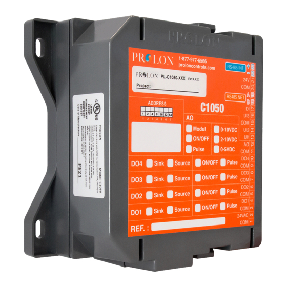
General Information PL-C1050 Water Loop Controller Description The PL-C1050 Water Loop controller is designed to control a water loop system comprised of a boiler and a water tower with an internal pump. The built-in microprocessor offers precise digital control to maximize performance. The available control sequences are fully configurable, either locally or remotely with free software. -
Page 5: Components
Components Component Identification 24VAC BIAS THERM BIAS THERM Figure 1 - Component Identification Legend: A - Analog Input Signal Mode Jumpers B - Addressing dipswitch C - Jumpers for terminating and bias resistors for the INT port (see I) D - Jumpers for terminating and bias resistors for the NET port (see K) E - SOURCE/SINK dipswitch for Output 4 F - SOURCE/SINK dipswitch for Output 3 G - SOURCE/SINK dipswitch for Output 2... -
Page 6: Leds
The example on Figure 3 shows the switches 1, 2 and 4 on the ON position. So the corresponding values are 1, 2 and 8, giving an address sum of 11. (1+2+8=11) The Prolon network allows a maximum of 127 addresses, therefore 127 controllers. Figure 3 - Addressing Dipswitches... -
Page 7: Input And Output Identification
The C1050 Water Loop Controller has 2 separate communication ports offering the same functionality on each. Both act as ports for incoming Modbus communications from other Prolon devices or interfaces, such as a Network Controller or remote computer with Prolon Focus software. -
Page 8: Inputs
Inputs Analog Input The C1050 series controllers are equipped with three general purpose analog inputs. These inputs can be configured to receive signals of the following types: • Thermistor (Ω) • 0-5V • 4 -20mA • 0-10V When a thermistor is used, the thermistor must be 10KΩ TYPE 3. -
Page 9: Auxiliary Digital Input
Auxiliary Digital Input The C1050 Water Loop controller has a digital input that used for visualisation purposes only. It can detect an open or closed contact. The status of the input does not affect the sequence in any way. 24VAC Contact Figure 7 - Connecting the Auxiliary Digital Input REV. -
Page 10: Outputs
The C1050 Water Loop controller contains 5 configurable outputs. The first 4 outputs are ON-OFF triac outputs. Output 5 is an analog 0-10VDC ON-OFF or modulating output, fully customizable via the Prolon Focus software. An integrated resettable fuse protects each of the outputs of the C1050 against current surges and short circuits. This protection will cut the current to the output as soon as an overload condition is detected. -
Page 11: Typical Connection Of Digital Outputs 1 To 4
2) Switch position to obtain a SINK passive output. Switch for Output 4 Isolated dry contact (On/O ) Figure 9 - Output in SINK mode Typical Connection of Digital Outputs 1 to 4 Two types of configurations are possible: 1) Active output (SOURCE). The C1050 is actively powering the load. External Load Figure 10 - Connection of Active Outputs 3 and 4 2) Passive output (SINK). -
Page 12: Typical Connection Of Analog Output
Typical Connection of Analog Output Two types of configuration are possible: 1) The C1050 powers the load and provides a control signal. 24 VAC power (From terminal block #2 of the controller) Controlled 0-10v Load Figure 12 - Connecting the Analog Output (Controller Powered) 2) The C1050 only provides the control signal to the load, which is powered by an external source. -
Page 13: Power Source / Network
Power Source The Prolon C1050 controller is powered by a 24 VAC power source connected using the "COM" terminal and the "24 VAC" terminal (see Figure 14). The common for all inputs and outputs are the same as the power source’s common (exception: when an output is set to passive, the common for this output will not correspond to the power source common). -
Page 14: Technical Specifications
Certification: UL916 Energy Management Equipment, CAN/CSA-C22.2, RoHS, FCC part 15: 2012 class B The performance specifications are nominal and conform to acceptable industry standards. Prolon Inc. will not be liable for damages resulting from misapplication or misuse of its products. -
Page 15: Compliance
Caution: Any changes or modifications not approved by Prolon can void the user’s authority to operate the equipment. Note: This equipment has been tested and found to comply with the limits for a Class B digital device, pursuant to part 15 of the FCC Rules. -
Page 16: Overall Dimensions
No part of this document may be photocopied or reproduced by any means, or translated to another language without prior written consent of Prolon. All specifications are nominal and may change as design improvements are introduced. Prolon shall not be liable for damages resulting from misapplication or misuse of its products.
Need help?
Do you have a question about the C1050 Series and is the answer not in the manual?
Questions and answers