Sign In
Upload
Manuals
Brands
Prolon Manuals
Controller
C1050 Series
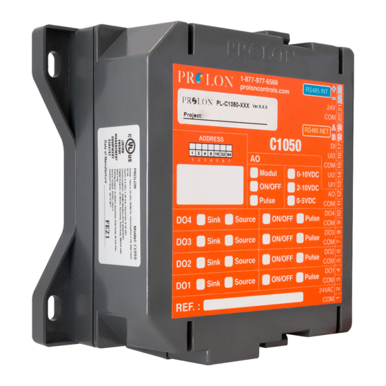
Prolon C1050 Series Manuals
Manuals and User Guides for Prolon C1050 Series. We have
7
Prolon C1050 Series manuals available for free PDF download: Technical Reference Manual, Specifications And Operational Manual, Hardware Manual
Prolon C1050 Series Technical Reference Manual (98 pages)
Brand:
Prolon
| Category:
Control Systems
| Size: 14 MB
Table of Contents
Table of Contents
3
Section 1 - Introduction
4
About Us
5
Prolon Key Concepts
6
Prolon Product Guide
7
Factory Wired Control Cabinets
9
Section 2 - System Architecture
10
Typical Prolon System Architecture
11
Master - Follower Communication Principle
12
Function-Related Network Positioning of Controllers
13
INT/NET Communication Bus Hierarchy
14
Section 3 - Network Topology
15
Network Layout
16
Master Location Within Its Own Network
16
Addressing Principles
17
Typical Prolon Wiring Schematics
18
Section 4 - I/O and Wiring Diagrams
21
Section 5 - Connections, Setup & Start-Up
48
Connecting Sensors & Peripherals
49
Input Jumper Configuration
50
Term / Bias Resistors (Jumpers)
50
Controller Addressing Methods
51
Cabling
52
System Start-Up
53
Section 6 - TREE-COM Wireless Communication Module
55
PL-TREE-COM Principles
56
PL-TREE-COM Installation Scenarios
59
Measuring Signal Quality with NFC
64
Android
65
Ios
66
Low Signal Quality Best Practices (Focus PC Only)
67
Section 7 - Connection Using Laptop
69
How to Connect a Computer to Prolon Controllers
70
Section 8- Navigating Using Laptop & Prolon Focus
71
Prolon Focus - Computer Access and Controller
72
Testing the System
75
Section 9 - Setting up a Zoning System (Focus Software)
79
Setting up a Zoning System with Prolon
80
Creating a Changeover Bypass System ("VVT")
81
Creating a VAV System (Variable Air Volume)
89
Annex a (Proportional + Integral Control)
93
Annex B (Math Function Examples)
96
Advertisement
Prolon C1050 Series Specifications And Operational Manual (18 pages)
Rooftop Controller
Brand:
Prolon
| Category:
Controller
| Size: 2 MB
Table of Contents
Table of Contents
2
General Information
4
PL-C1050 Basic Rooftop Controller
4
Description
4
General Behaviour
4
Operating Sequence
5
General
5
Occupied Mode
5
Unoccupied Mode
5
Components
6
Component Identification
6
Figure 1 - Component Identification
6
Leds
7
Address Configuration for Networking
7
Figure 2 - Leds Identification
7
Figure 3 - Addressing Dipswitches
7
Input and Output Identification
8
Figure 4 - Input and Output Identification
8
Inputs
9
Analog Input
9
Temperature Sensors
9
Figure 5 - Analog Input
9
Figure 6 - Connecting the Sensors
9
Occupancy Mode (Night Setback)
10
Proof of Fan
10
Figure 7 - Night Setback Contact Conection
10
Figure 8 - Connecting the Proof of Fan Contact to the Controller
10
Outputs
11
Output Specifications
11
Typical Connection of the Triac Outputs 1 through 4
12
Typical Connection of Output #5
12
Figure 9 - Conection of Outputs 3 and 4
12
Figure 10 - Connecting the Analog Output (External Power)
12
DMUX-4J Connection on Output 2 for Stage 3 or 4 Cooling
13
Figure 11 - Connecting the DMUX-4J (Powered by C1050)
13
PTA2 Connection on Output 2 for Analog Cooling
14
Figure 12 - Connecting the PTA2 (Powered by C1050)
14
Power Source & Network
15
Power Source
15
Network Communication
15
Figure 13 - Connecting the 24VAC Power Source
15
Figure 14 - Connecting to the Network
15
Technical Specifications
16
Compliance
17
FCC User Information
17
Industry Canada
17
Overall Dimensions
18
Figure 15 - C1050 Size Diagram
18
Prolon C1050 Series Hardware Manual (17 pages)
Humidifier Controller
Brand:
Prolon
| Category:
Controller
| Size: 2 MB
Table of Contents
Table of Contents
2
General Information
4
PL-C1050 Humidity Controller
4
Description
4
General Behaviour
4
Operating Sequence
5
Humidification
5
Dehumidification
5
Components
6
Component Identification
6
Figure 1 - Component Identification
6
Leds
7
Address Configuration for Networking
7
Figure 2 - Leds Identification
7
Figure 3 - Addressing Dipswitches
7
Input and Output Identification
8
Figure 4 - Input and Output Identification
8
Inputs
9
Analog Input
9
Outside Temperature Sensor
9
Figure 5 - Analog Input
9
Figure 6 - Connecting the Outside Air Sensor
9
Relative Humidity Sensors
10
Proof of Fan
10
Figure 7 - Connecting the Humidity Sensors
10
Figure 8 - Connecting the Proof of Fan
10
Outputs
11
Output Specifications
11
Configuration of Outputs 3 and 4
11
Figure 9 - Output in SOURCE Mode
11
Typical Connection of the Triac Outputs 3 and 4
12
Figure 10 - Output in SINK Mode
12
Figure 11 - Connection of Active Outputs 3 and 4
12
Figure 12 - Connection of Passive Outputs 3 and 4
12
Typical Connection of the Analog Output
13
Figure 13 - Connecting the Analog Output (Controller Powered)
13
Figure 14 - Connecting the Analog Output (External Power)
13
Power Source / Network
14
Power Source
14
Network Communication
14
Figure 15 - Connecting the 24VAC Power Source
14
Figure 16 - Connecting to the Network
14
Technical Specifications
15
Compliance
16
FCC User Information
16
Industry Canada
16
Overall Dimensions
17
Figure 17 - C1050 Size Diagram
17
Advertisement
Prolon C1050 Series Hardware Manual (17 pages)
Boiler Controller
Brand:
Prolon
| Category:
Controller
| Size: 2 MB
Table of Contents
Table of Contents
2
General Information
4
PL-C1050 Boiler Controller
4
Description
4
General Behaviour
4
Operating Sequence
5
General
5
Parallel Pump Sequence
5
Follower Pump Sequence
5
Components
6
Component Identification
6
Figure 1 - Component Identification
6
Leds
7
Address Configuration for Networking
7
Figure 2 - Leds Identification
7
Figure 3 - Addressing Dipswitches
7
Input and Output Identification
8
Figure 4 - Input and Output Identification (Staged Boiler)
8
Figure 5 - Input and Output Identification (Modulating Boiler)
8
Inputs
9
Analog Input
9
Temperature Sensors
9
Figure 6 - Analog Input
9
Figure 7 - Connecting the Temperature Sensors
9
Proof of Pump
10
Figure 8 - Connnecting the Proof of Pump Contacts to the Controller
10
Outputs
11
Output Specifications
11
Configuration of Digital Outputs
11
Figure 9 - Output in SOURCE Mode
11
Typical Connection of Digital Outputs
12
Figure 10 - Output in SINK Mode
12
Figure 11 - Connection of Active Outputs 3 and 4
12
Figure 12 - Connection of Passive Output 3 and 4
12
Typical Connection of the Analog Output
13
Figure 13 - Connecting the Analog Output (Controller Powered)
13
Figure 14 - Connecting the Analog Output (External Power)
13
Power Source / Network
14
Power Source
14
Network Communication
14
Figure 15 - Connecting the 24VAC Power Source
14
Figure 16 - Connecting to the Network
14
Technical Specifications
15
Compliance
16
FCC User Information
16
Industry Canada
16
Overall Dimensions
17
Figure 17 - C1050 Size Diagram
17
Prolon C1050 Series Hardware Manual (17 pages)
Heatpump Controller
Brand:
Prolon
| Category:
Controller
| Size: 2 MB
Table of Contents
Table of Contents
2
General Information
4
PL-C1050 Heatpump Controller
4
Description
4
General Behaviour
4
Operating Sequence
5
General
5
Occupied Mode
5
Unoccupied Mode
5
Components
6
Component Identification
6
Figure 1 - Component Identification
6
Leds
7
Addressing Dipswitch Configuration for Network Communication
7
Figure 2 - Leds Identification
7
Figure 3 - Addressing Dipswitches
7
Input and Output Identification
8
Figure 4 - Input and Output Identification
8
Inputs
9
Analog Input
9
Temperature Sensors
9
Figure 5 - Analog Input
9
Figure 6 - Connecting the Temperature Sensors
9
Occupancy Mode (Night Setback)
10
Proof of Fan
10
Figure 7 - Night Setback Contact Connection
10
Figure 8 - Connecting the Proof of Fan Contact to the Controller
10
Dry Contact for Alarm Signal
11
Figure 9 - Connecting the Alarm Contact to the Controller
11
Outputs
12
Output Specifications
12
Typical Connection of the Triac Outputs 1 through 4
13
Typical Connection of Output #5
13
Figure 10 - Connection of Outputs 3 and 4
13
Figure 11 - Connecting the Analog Output (External Power)
13
Power Source / Network
14
Power Source
14
Network Communication
14
Figure 12 - Connecting the 24VAC Power Source
14
Figure 13 - Connecting to the Network
14
Technical Specifications
15
Compliance
16
FCC User Information
16
Industry Canada
16
Overall Dimensions
17
Figure 14 - C1050 Size Diagram
17
Prolon C1050 Series Hardware Manual (17 pages)
FlexIO Controller
Brand:
Prolon
| Category:
Controller
| Size: 2 MB
Table of Contents
Table of Contents
2
General Information
4
PL-C1050 FLX Controller
4
Description
4
Features
4
Components
5
Components Identification
5
Figure 1 - Component Identification
5
Leds
6
Address Configuration for Networking
6
Figure 2 - Leds Identification
6
Figure 3 - Addressing Dipswitches
6
Input and Output Identification
7
Figure 4 - Input and Output Identification
7
Inputs
8
Analog Input
8
Signal: Thermistor
8
Figure 5 - Analog Input
8
Figure 6 - Connecting a Temperature Sensor to Analog Input 1
8
Signal: Contact
9
Signal: Voltage
9
Figure 7 - Connecting a Dry Contact to Analog Input 1
9
Figure 8 - Connecting Voltage Based Sensors
9
Signal: Current
10
Figure 9 - Connecting Current Based Sensors
10
Outputs
11
Output Specifications
11
Configuration of Digital Outputs
11
Figure 10 - Output in SOURCE Mode
11
Typical Connection of Digital Outputs
12
Figure 11 - Output in SINK Mode
12
Figure 12 - Connection of Active Outputs 3 and 4
12
Figure 13 - Connection of Passive Outputs 3 and 4
12
Typical Connection of Analog Outputs
13
Figure 14 - Connecting the Analog Output (Controller Powered)
13
Figure 15 - Connecting the Analog Output (External Power)
13
Power Source / Network
14
Power Source
14
Network Communication
14
Figure 16 - Connecting the 24VAC Power Source
14
Figure 17 - Connecting to the Network
14
Technical Specifications
15
Compliance
16
FCC User Information
16
Industry Canada
16
Overall Dimensions
17
Figure 18 - C1050 Size Diagram
17
Prolon C1050 Series Hardware Manual (16 pages)
Water Loop Controller
Brand:
Prolon
| Category:
Control Systems
| Size: 2 MB
Table of Contents
Table of Contents
2
General Information
4
PL-C1050 Water Loop Controller
4
Description
4
General Behaviour
4
Components
5
Component Identification
5
Figure 1 - Component Identification
5
Leds
6
Address Configuration for Networking
6
Figure 2 - Leds Identification
6
Figure 3 - Addressing Dipswitches
6
Input and Output Identification
7
Figure 4 - Input and Output Identification
7
Inputs
8
Analog Input
8
Temperature Sensors
8
Figure 5 - Analog Input
8
Figure 6 - Connecting the Water Temperature Sensors
8
Auxiliary Digital Input
9
Figure 7 - Connecting the Auxiliary Digital Input
9
Outputs
10
Output Specifications
10
Configuration of Digital Outputs 1 to 4
10
Figure 8 - Output in SOURCE Mode
10
Typical Connection of Digital Outputs 1 to 4
11
Figure 9 - Output in SINK Mode
11
Figure 10 - Connection of Active Outputs 3 and 4
11
Figure 11 - Connection of Passive Output 3 and 4
11
Typical Connection of Analog Output
12
Figure 12 - Connecting the Analog Output (Controller Powered)
12
Figure 13 - Connecting the Analog Output (External Power)
12
Power Source / Network
13
Power Source
13
Network Communication
13
Figure 14 - Connecting the 24VAC Power Source
13
Figure 15 - Connecting to the Network
13
Technical Specifications
14
Compliance
15
FCC User Information
15
Industry Canada
15
Overall Dimensions
16
Figure 16 - C1050 Size Diagram
16
Advertisement
Related Products
Prolon C1000 Series
Prolon M2000 SERIES
Prolon NC2000
Prolon PL-C1000 Series
Prolon PL-C1000-BLR
Prolon PL-C1000-FLX
Prolon PL-C1000-HP
Prolon PL-C1000-HPS
Prolon PL-C1000-HU
Prolon PL-C1000-RTU
Prolon Categories
Controller
Control Systems
Thermostat
Accessories
Media Converter
More Prolon Manuals
Login
Sign In
OR
Sign in with Facebook
Sign in with Google
Upload manual
Upload from disk
Upload from URL