Table of Contents
Advertisement
Quick Links
Advertisement
Table of Contents

Related Manuals for AMGO 409-HP


Summary of Contents for AMGO 409-HP
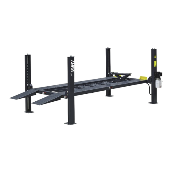
- Page 1 Original Four Post Parking Lift Model: 409-HP...
-
Page 2: Table Of Contents
CONTENTS Product Features and Specifications ............. 1 Installation Requirement ..............2 Steps of Installation ................4 Exploded View .................. 22 Test Run ...................28 Operation Instruction .................29 Maintenance ..................30 Trouble Shooting ................31 Lift Disposal..................31... -
Page 3: Product Features And Specifications
I. PRODUCT FEATURES AND SPECIFICATIONS 4-POST MODEL 409-HP FEATURES · Single point manual safety release, more convenient and more reliable for decent operation. · Four mechanical locking devices, each equipped with both primary and secondly safety locks. · Power-side column can be installed at both side, front or rear. -
Page 4: Installation Requirement
II. INSTALLATION REQUIREMENT A. TOOLS REQUIRED Tape Measure (7.5m) Carpenter’s Chalk Hammer Screw Sets Level Bar Pliers Lock Wrench English Spanner (12") Socket Head Wrench Wrench set , 13 , 14 , 15 , 17 , 19... - Page 5 B. Equipment storage and installation requirements. The equipment should be stored or installed in a shady, normal temperature, ventilated and dry place. C. The equipment should be unload and transfer by forklift. Fig.3 D. SPECIFICATIONS OF CONCRETE (See Fig. 4) Specifications of concrete must be adhered to the specification as following.
-
Page 6: Steps Of Installation
III. STEPS OF INSTALLATION A. Check the parts before assembly 1. Packaged lift and Hydraulic Power Unit (See Fig. 5) Fig. 5 2. Open the outer packing carefully, check the parts according to the shipment list. (See Fig. Power-side Cross Column Offside Parts box... - Page 7 5. Move aside the parts and check the parts according to the shipment parts list (See Fig. 8). Fig.8 Optional kit 6. Open the carton of parts and check the parts according to the parts box list(See Fig. 9). Fig. 9...
- Page 8 Make sure the size is right and base is flat (see Fig. 11). Note: Reserve space front and behind the installation site. Use a carpenter’s chalk line to establish installation layout Fig.11 MODEL 201 3/8” 122 1/4” 235 5/8” 409-HP 5115mm 3106mm 5984mm...
- Page 9 C. Install cross beams (See Fig.12, Fig.13). The power-side column need to be installed according to the installed position of the safety lock release handle. Hole towards inside Fig.12 Fig.13...
- Page 10 D. Install the Safety Ladders. 1. Take off the pulley safety cover and unscrew a nut of the safety ladders, and then adjust the four lower nuts to be at the same position. Then install the safety ladder (See Fig. 14). Unscrew a nut of the safety ladders Safety cover...
- Page 11 2. Install Safety Ladders (See Fig. 15). This height for four threaded rod of safety ladders should be the same. Safety ladder pass through the hole of the top plate, then tighten the two nuts Fig. 15 E. Put the cross beams at the same height and lock on the safety ladder (See Fig.
- Page 12 F. Install power side platform. 1. Install the power side platform on the cross beams by a fork lift or manual, offset the cross beams to the outside till the pulleys of both platforms can rest into the cross beams’ slots , Install the power side platform and screw up the bolts.
- Page 13 2. Install tire stop plate with bolts and washer on the platform: Tighten the platform on cross beam B with bolts, tighten the tire stop plate on cross beam A with bolts Note: The bolts for the side with tire stop plate is longer, pay attention when choosing the bolts (See Fig.18) Cross beam B...
- Page 14 Install offside platform and limit slider, then install the bolts for the platform strengthen plate, check the plumbness of columns with level and adjusting with the shims (See Fig. 19). Install the bolts for the platform strengthen plate Level bar Position the slider along bent edges of the columns.
- Page 15 1. Pass through the cables from the platform to the columns according to the number of the cables (See Fig. 20) Fig. 20 Cable installation diagram ③ ④ Cable Length for 409-HP 133 7/4” 388 3/4” 196” 326 1/8” (inc. connecting fitting) 3400mm 9875mm...
- Page 16 2. The cable goes through the cross beam to top plate of columns and be screwed with cable nuts (See Fig. 21). Cable goes between the Cable pass through top big pulley and tension plate and be screwed pulley with cable nuts. Fig.
- Page 17 3. Illustration for platform cables (See Fig. 22). ○ Cable ○ Cable ○ Cable ○ Cable Cable ○ ○ Cable ○ Cable Cable ○ ○ Cable ○ Cable Cable ○ ○ Cable Cable ○ M10*120 Socket Bolt Fig. 22...
- Page 18 I. Install connecting bar for safety device and release handle (See Fig. 23). Cross beam B View B Cross beam A Fig. 23 View A Safety lock rotating Connecting bar device Connecting bar View A Pass the connecting bar through middle of safety lock rotating device of cross beam A/B Align the two connection holes of connecting...
- Page 19 Install power unit and connecting tube Note: Power unit must be installed at the same side of the safety release handle. 1. Install Power unit on the cross beam A, the installation of Connection tube is as Fig.24 Cross beam A Cross beam B Car in direction...
- Page 20 K. Install Hydraulic System 1. For power unit attached to the column of cross beam A (See Fig. 25) Note: Oil hoses connected to oil cylinder must be passed above the cable to avoid the oil hose scratched by cable. Oil return hose Cylinder inlet port Retainer...
- Page 21 L. Install Electrical System Connect the power source on the data plate of power unit. Note: For the safety of operators, the power wiring must contact the earth well. Single phase motor (See Fig. 26) Connecting the two power supply live wires to terminals of AC contactor marked L1, L3 respectively.
- Page 22 N. Install drive-in ramp, jack tray and plastic oil pans (See Fig. 28). According to the below diagram screw up the M16*30 bolts, then attach the drive-in ramp. 64(Optional kit) 68(Optional kit) Screw the M16*30 bolts to the side hole of the cross beam Attach the drive-in ramp on the hex bolts.
- Page 23 P. For optional kits installation. 1. Install optional caster kits or Rolling jack (See Fig. 30) 67-2 67-3 67-4 67-5 67-6 67-7 67-8 Fig. 30 Q. Fix the anchor bolts 1. Prepare the anchor bolts (See Fig. 31). Washer Spring washer Fig.
-
Page 24: Exploded View
IV. EXPLODED VIEW Model 409-HP Fig. 33... - Page 25 PARTS LIST FOR MODEL 409-HP Item Part# Description Qty. Note 11410074-01 Power-side Column 11410075-01 Offside Column 11410050 Cross Beam A 11410076-01 Offside Platform 11410077A-01 Power-side Platform 11410053 Cross Beam B 1104233003C Folding drive-in ramp 10209043 Hex Bolt M8*20 10209033 Washer φ8...
- Page 26 Item Part# Description Qty. Note 10600015 Socket Bolt M10*120 Connecting bar for safety device 11410069-01 φ19*2410mm 11410024 Connecting tube 10209032 Socket bolt M8*25 10217005 Plastic ball M10 10209056 Nylok Nut M10 10410025 Socket bolt M8*35 11410026 Safety release handle 11410100 Extended release handle 10209004 Rubber ring φ8*φ20*3...
- Page 27 4.1 CYLINDERS EXPLODED VIEW Fig. 34 Note Item Part# Description Qty. 12-1 10420059 Dust Ring 10420060 Y- Ring ISI 12-2 11410082 Head Cap 12-3 10410083 O- Ring 12-4 11410078-01 Bore Weldment 12-5 11410079-01 Piston Rod 12-6 11410085 12-7 10410086 Support Ring 12-8 10410087 Y- Ring OSI...
- Page 28 4.2 CROSS BEAM EXPLODED VIEW Fig.35 Item Part# Description QTY. Note 10206032 Snap ring φ25 10410099 Spring φ14*φ2.5*100 11410063-01 Connecting bar of safety lock 1104572003A Safety lock rotating device 11410064-01 Connecting bar of safety lock 11420041A Pulley Pin 10420132A Pulley Bush φ41.3*φ35.1*20 3-10 11420040A Pulley pin sleeve...
- Page 29 Manual power unit 110V/60Hz (071109) Fig.36 Item Part# Description Qty. Item Part# Description Qty. 81400180 Rubber Pad 10420070 Push button 80101034 Starting capacitor 81400559 AC connector Round Head Bolt with 10420148 80101039 Wire plug washer Cover of Motor 81400527 Cover of capacitor 81400528 Terminal Box 81400363...
-
Page 30: Test Run
Illustration of hydraulic valve for power unit Oil return port Relief valve Release valve Throttle Check valve valve Oil outlet Handle for Oil outlet relief valve Fig.37 V. TEST RUN 1. Fill the reservoir with approximately 11L Hydraulic Oil (Note: In consideration of Power Unit’s durability, please use Hydraulic Oil 46#). -
Page 31: Operation Instruction
Circuit Diagram of Hydraulic System 1. Filter 2. Gear pump 3.Check valve 4. Relief Valve 5. Motor 6. Throttle Valve 7. Release Valve 8. Cylinder For Four-post lift Fig.38 VI. OPERATION INSTRUCTIONS To lift vehicle 1. Keep clean of environment near the lift. 2. -
Page 32: Maintenance
VII. MAINTENANCE SCHEDULE Monthly: 1. Lubricate cable with lubricant; 2. Check all cable connection, bolts and pins to insure proper mounting; 3. Make a visual inspection of all hydraulic hoses/lines for possible wear or leakage; 4. Lubricate all rollers, safety devices with 90wt. gear oil or equivalent. Every six months: 1. -
Page 33: Trouble Shooting
VIII. TROUBLE SHOOTING TROUBLE CAUSE REMEDY 1. Start Button does not work 1.Replace start button 2.Wiring connections are not in good 2.Repair all wiring connections Motor does condition not run 3. Motor burned out 3.Repair or replace motor 4. AC contactor burned out 4.Replace AC contactor 1. - Page 34 AMGO HYDRAULIC CORPORATION 1931 Joe Rogers Blvd, Manning, South Carolina, Zip:29102 Tel: (803) 505-6410 Fax: (803) 505-6410 服 Manual No.: 72247401 Revision Date: 2022/08...
Need help?
Do you have a question about the 409-HP and is the answer not in the manual?
Questions and answers