Advertisement
Quick Links
Advertisement

Related Manuals for AMGO 409-P


Summary of Contents for AMGO 409-P
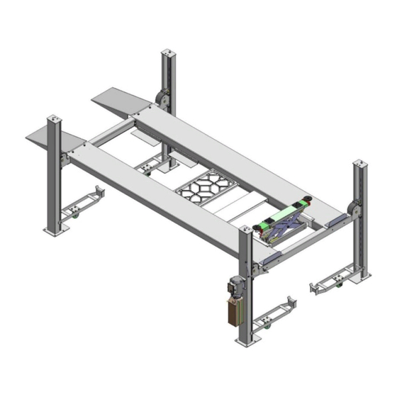
- Page 1 409-P 409-HP...
-
Page 2: Table Of Contents
CONTENTS Product Features and Specifications ............. 1 Installation Requirement ……………………………………………………………………………… 2 Steps of Installation …................ 3 Exploded View ................. 26 Test Run ………..................30 Operation Instruction .................31 Maintenance ..................31 Trouble Shooting ................32 Parts List ..................33 I. PRODUCT FEATURES AND SPECIFICATIONS... -
Page 3: Installation Requirement
4-POST MODEL 409-P 409-HP FEATURES · Single point manual safety release. · Four mechanical locking devices, each equipped with both primary and secondly safety locks. · Power-side column can be installed at both side, front or rear. · Non-skid diamond platforms and adjustable safety lock ladders. - Page 4 A. TOOLS REQUIRED ✓ Tape Measure (7.5m) Carpenter’s Chalk ✓ Screw Sets ✓ ✓ Hammer ✓ Level Bar Pliers ✓ ✓ English Spanner (12") Lock Wrench ✓ Wrench set Socket Head Wrench , 13 , 14 , 15 , 17 , 19 , 24...
-
Page 5: Steps Of Installation
Specifications of concrete must be adhered to the specification as following. Failure to do so may result in lift and/or vehicle falling. 1. Concrete must be thickness 4” minimum and without reinforcing steel bars, and must be dried completely before the installation. 2. - Page 6 Powerside Cross Column Offside Parts box Drive-in Platform Beam Platform Ramp Shipment Parts List Fig. 5 3. Take off the drive-in ramps and columns (See Fig.6 ) Fig. 6 4. Loose the screws of the upper package stand, take off the offside platform, take out the parts inside the powerside platform, then remove the package stand.
- Page 7 (See Fig. 8) Fig. 8 7. Check the parts of the parts bag according to the parts bag list (See Fig. 9) Fig. 9 B. Use a carpenter’s chalk line to establish installation layout as per Table 1...
- Page 8 Make sure the size is right and base is flat (see Fig. 10). Note: Reserve space front and behind the installation site. Use a carpenter’s chalk line to establish installation layout Fig. 10 MODEL 409-P 185” 126 1/8” 224” 409-HP 196 7/8” 126 1/8”...
- Page 9 The powerside column need to be installed according to the installed position of the safety lock release handle. Hole towards inside Fig. 11 Fig. 12 D. Install the Safety Ladders.
- Page 10 1. Take off the pulley safety cover and unscrew a nut of the safety ladders, and then adjust the four lower nuts to be at the same position. Then install the safety ladder (See Fig. 13). Unscrew a nut of the safety ladders Limited Pin Insert the safety ladder...
- Page 11 This height for four threaded rod of safety ladders should be the same. Fig. 14 Safety ladder pass through the hole of the top plate, then tighten the two nuts E. Put the cross beams at the same height and lock on the safety ladder (See Fig.
- Page 12 1. Install the power side platform on the cross beams by a fork lift or manual, offset the cross beams to the outside till the pulleys of both platforms can rest into the cross beams’ slots , Install the power side platform and screw up the (See Fig.16) bolts.
- Page 13 2. Install tire stop plate with bolts and washer on the platform: Tighten the platform on cross beam B with bolts, tighten the tire stop plate on cross beam A with bolts Note: The bolts for the side with tire stop plate is longer, pay attention when choosing the bolts (See Fig.17) Instruction:...
- Page 14 G. Install offside platform and plastic block, then install the bolts for the platform strengthen plate, check the plumbness of columns with level and adjusting with the shims (See Fig. 18). Install the bolts for the platform strengthen plate Level bar Position the slide blocks along the bent edges of the columns.
- Page 15 1. Pass through the cables from the platform to the columns according to the number of the cables (See Fig. 19) ③ ④ ① ② Cable Length for 409-P 124” 1/4” 187” 301 3/8” (inc. connecting fitting) Length for 409-HP 132 3/4”...
- Page 16 2. The cable goes through the cross beam to top plate of columns and be screwed with cable nuts (See Fig. 20). Cable goes between Cable pass through top the big pulley and plate and be screwed tension pulley with cable nuts. Fig.
- Page 17 3. Illustration for platform cables (See Fig. 21). Limit block ○ Cable ○ Cable ○ ○ Cable Cable ○ Cable ○ Cable ○ Cable ○ Cable ○ Cable ○ Cable ○ Cable ○ Cable ○ Cable ○ Cable M10*120 Hex Bolt Fig.
- Page 18 I. Install connecting bar for safety device and release handle (See Fig. 22) Cross beam B View B Cross beam A Safety lock rotated Device assy. View A Connecting bar Connecting bar According to the above diagram, Install Pass through the connecting lock release handle to the connecting bar from the safety lock bar with M8*35 bolts and washers on...
- Page 19 J. Install power unit Note: Power unit must be installed near the safety release handle 1. Install Power unit on the cross beam A, the installation of connection tube as Fig.23 Car in direction Cross beam B Cross beam A Fig.
- Page 20 2. Install Power unit on the cross beam B (See Fig.24) Cross beam B Fig. 24 Car in Fixing plate direction GUDI Install M8*25 Socket bolt with washer to these two holes.
- Page 21 K. Install Hydraulic System 1. For power unit attached to the column of cross beam A (See Fig. 25) Note: Oil hoses connected to oil cylinder must be passed above the cable to avoid the oil hose scratched by cable. cylinder inlet port Oil return Retainer...
- Page 22 Note: The oil return hose can be adjusted when installation c、d Fig. 26 L. Install Electrical System Connect the power source on the data plate of Power Unit. Note: For the safety of operators, the power wiring must connect the floor well. Single phase motor (See Fig.27) 1.
- Page 23 a. The source wires (L1, L2, L3) are connected with terminals of AC contactor marked L1, L2, L3 respectively. b. Terminals 4# of control button is connected with terminals of AC contactor marked L1; wire 3# is connected with A1 terminals of control button. M.
- Page 24 According to the below diagram screw up the M16*30 bolts, then attach the drive- in ramp. Screw the M16*30 bolts to the side hole of the cross beam Attach drive-in ramp with the bolts Fig. 29 O. Install Rear wheel stop plates (See Fig.
- Page 25 stop plates to the drive-in ramp position. Fig. 30 P. Install Layer Board Assy. for Drive in Ramp Take down the Drive in Ramp, and put it in the platform and layer board assy. (See Fig. 31) Fig. 31 For optional kits installation. 1.
- Page 26 67-2 67-3 67-4 67-5 67-6 67-7 Fig. 32 67-8 2. Install optional motor fixing bracket (See Fig. 33,34). Optional motor fixing bracket Fig. 33 Fig. 34 Motor fixing bracket on cross beam A Motor fixing bracket on cross beam Q. Fix the anchor bolts 1.
-
Page 27: Exploded View
Do not tighten the anchor bolts (See Fig. 36). Note: The tightening torque for the anchor bolt is 150N.m ,Anchor bolts driven into the ground at least 90mm Expand Drillin Clearin Fig. 36 IV. EXPLODED VIEW Model 409-P/409-HP... - Page 28 Fig. 37 CROSS BEAM...
- Page 29 Fig.38 CYLINDERS Fig. 39 Manual power unit 220V,60Hz...
- Page 30 Fig.43 Fig. 40 Illustration of hydraulic valve Manual hydraulic power unit 110V.60Hz,single phase(Fig. 41)
-
Page 31: Test Run
Protective ring Oil return port Release valve Relief valve Check valve Throttle valve Plug Oil Outlet Handle for Release valve Fig. 41 V. TEST RUN Fill the reservoir with Hydraulic Oil (Note: In consideration of Power Unit’s... -
Page 32: Operation Instruction
durability,please use Hydraulic Oil 46#). Press the control button, the cables will be strained. Check whether the cables match the pulley. Make sure the cables are not across. 3. Press the release valve handle to lock the cross-beam to the safety ladders, and then adjust the platforms to be level by adjusting the nuts of safety ladders. -
Page 33: Maintenance
To lift vehicle 1. Keep clean of environment near the lift. 2. Drive vehicle to the platform and put on the brake. 3. Take off the drive-in ramp, install rear wheel stop plates to the drive-in ramp position. 4. Turn on the power and press the control button, raise the lift to the working position. -
Page 34: Trouble Shooting
VIII. TROUBLE SHOOTING TROUBLE CAUSE REMEDY 1. Button does not work 1.Replace button 2.Wiring connections are not in good 2.Repair all wiring connections Motor does condition not run 3. Motor burned out 3.Repair or replace motor 4. AC contactor burned out 4.Replace AC contactor 1.Motor runs in reverse rotation 1.Reverse two power wire... -
Page 35: Parts List
IX. PARTS LIST FOR MODEL 409-P 409-HP Qty. Item Part# Description Note 409-P 409-HP 410001 Power-side Column 410074 410002 Offside Column 410075 410050 Cross Beam A 410051 Offside Platform 410076 410052 Powerside Platform 410077 Cross Beam B 410053 Drive-in ramp... - Page 36 Hex Bolt 410105 Plastic block 410016A Item Part# Description Note 409-P 409-HP Socket bolt 410017 Shim 620065/201090 410167 ○ 1 Cable 410171 410168 ○ 2 Cable 410172 410166 ○ 3 Cable 410170 410165 ○ 4 Cable 410169 Hex Bolt 420020B...
- Page 37 410036 Protective hose Cup head bolt with washer 209145A Item Part# Description Note 409-P 409-HP 410029 Plastic cover for cross beam 410030 Spring Spring 420033 410501 Parts box 410502 Limit block 420239 410094 Rear wheel stop plate 410101 Layer board assy for drive in ramp...
- Page 38 Tension pulley 3-12 420035 Spacer 3-13 420174 Qty. Note Item Part# Description Item 409-P 409-HP 3-14 420171 Slack-cable safety lock (Left) 420175 3-15 Slack-cable safety lock(Right) 420240 Pin Bush For Slack-cable safety lock 3-16 420172 Snap ring 3-17 206019 Snap ring...
- Page 39 Gear Pump 81400294 Relief Valve 10209034 Qty. Item Part# Description Note 409-P 409-HP Spring Washer 81400295 Hex Screw 81400365 10209152 O-Ring Ties 85090167 Magnet of power units 81400290 Filter 81400412 81400088 Motor Push Button 10420070 Socket Bolt 81400463 O-Ring 81400287...
- Page 40 AMGO HYDRAULIC CORPORATION 1931 Jo Rogers Blvd, Manning, South Carolina, USA Tel: (803) 505-6410 Fax: (803) 505-6410...
- Page 41 Manual Part No:72147401 Revision Date:2017/10...
Need help?
Do you have a question about the 409-P and is the answer not in the manual?
Questions and answers