
Related Manuals for TapFlo LPX Series


Summary of Contents for TapFlo LPX Series
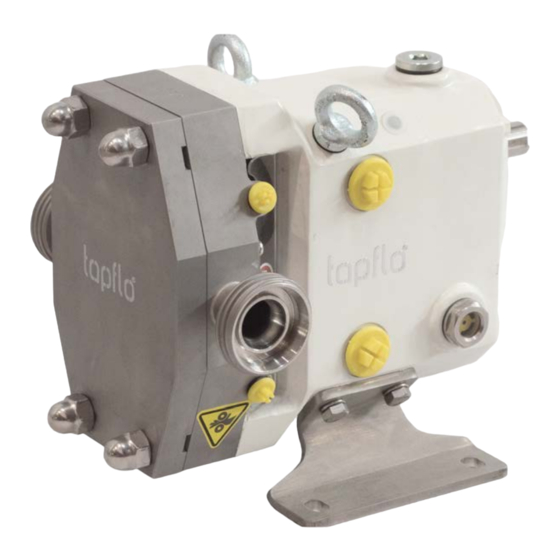
- Page 1 IOM manual Sanitary Positive Displacement Pump Tapflo LPX series 2023 | 1 Read this instruction manual carefully, before you install and operate the pump Pump models: 25-1 25-2 40-1 40-2 50-1 50-2 80-1 100-1...
-
Page 2: Table Of Contents
5.6. Install side strainers and traps ....................18 5.7. Install pressure gauges ......................19 5.8. Seal flush connections ......................19 5.9. CIP (Clean-In-Place) guidelines ....................20 5.10. Check coupling alignment ....................20 5.11. Check angular alignment..................... 21 Tapflo LPX series... - Page 3 Gear cover removal ......................35 7.7.2. Gear cover removal ......................35 7.7.3. Bearing removal ....................... 37 7.8. Pump assembly ........................37 7.8.1. Install front seals ......................38 7.8.2. Bearing assembly ......................38 7.8.3. Bearing adjustment ......................40 Tapflo LPX series...
- Page 4 Model 50-2 to 100-1 Pump Parts (-B- exploded view) ............63 9.8. Model 50-2 to 100-1 Pump Parts (-B- BOM Items) .............. 64 9.9. Maintenance kits ........................65 WARRANTY ..........................66 10.1. Warranty form ........................66 10.2. Returning parts ........................67 10.3. Warranty ..........................67 Tapflo LPX series...
-
Page 5: Safety
Replacement Equipment: Use only replacement parts and devices recommended by the manufacturer to maintain the integrity of the equipment. Make sure the parts are properly matched to the equipment series, model, serial number, and revision level of the equipment. Tapflo LPX series... - Page 6 WARNING! marked with a warning triangle. Hazards or unsafe practices which COULD result in severe personal injury or death. CAUTION! marked with a warning triangle. Hazards or unsafe practices which COULD result in minor personal injury or product or property damage. Tapflo LPX series...
-
Page 7: Replacement Labels
(A soft rubber roller also may be used to press the label into place). Apply all labels to be readable from the front of the pump. Fig. 1: Label locations Label Definition Entanglement hazard Replace plug with breather plug Tapflo LPX series... -
Page 8: Care Of Stainless Steel
CARE OF STAINLESS STEEL CARE OF STAINLESS STEEL NOTE! Tapflo recommends the use of an FDA-approved anti-seize compound on all threaded connections. 3.1. Care of stainless steel Corrosion resistance is greatest when a layer of oxide film is formed on the surface of stainless steel. -
Page 9: Introduction
DO NOT install, clean, service, or repair the pump unless all power is off and locked out. 4.1. Pump model designation 40-1 - 1SSE2D4Z - 30/129 - TRF 1. Tapflo Lobe Pump LPX = Tapflo Lobe Pump 2. Pump size (pump inlet dimension DN): Displacement Connection size litres/rev... - Page 10 = Bonfiglioli = SEW = Special 7. Assembly options: no sign. = Pump Unit on Baseplate = Pump Unit on Trolley = Pump Unit on Trolley with IP66 frequency inverter = Pump Unit on Trolley with Control switch Tapflo LPX series...
-
Page 11: Intended Use
Destruction Possible failures in the production process The Tapflo LPX Lobe Rotary Pump is exclusively intended for pumping liquids, especially in beverage and food installations as well as in comparable applications of the chemical, pharmaceutical and health care industries. -
Page 12: Pump Shaft Location
The mounting position may be easily reconfigured by changing the location of the mounting feet. The breather plug must be moved to the uppermost port and the level indicator should be in the lowest, side port in the gear cover. Tapflo LPX series... -
Page 13: Pump Dimensions
25-2 0.10 25 (1") 40-1 0.14 40 (1.5") 40-2 0.23 40 (1.5") 50-1 0.30 50 (2") 50-2 0.67 50 (2") 80-1 0.94 75 (3") 100-1 2.29 100 (4") 1200 NOTE! All weights in daN, mass in Kg. Tapflo LPX series... -
Page 14: Sound Level
100-1 max. RPM 4.7.4. Maximum particle size Port Connection Max. Theoretical Recommended Max. Model Inside Diameter Particle Size Particle Size (mm) (mm) (mm) 25-1 25-2 15.6 40-1 15.6 40-2 25.6 50-1 25.6 50-2 38.5 80-1 38.5 100-1 45.6 Tapflo LPX series... -
Page 15: Installation
The unit can be installed in any of the arrangements shown in Figure 4 through Figure 7 (the shaded area indicates the guard location). NOTE! When installing unit as shown in Figure 7, level the unit before installing the bolts. Tapflo LPX series... -
Page 16: Install Connections And Piping
5.2.3. Inlet piping Fig. 10: Pump Below Supply Install the pump below the supply liquid level to reduce the air in the system by flooded suction (Figure 10). Tapflo LPX series... -
Page 17: Install Check Valves
The check valve prevents backflow (air or fluid) to aid in the initial start-up by minimizing the required differential pressure supplied by the pump to start the flow (Figure 13). A. Closed Tank - produces a vacuum on liquid (Low Absolute Pressure) B. Check Valve (outlet) Tapflo LPX series... -
Page 18: Install Isolation Valves
Make the selection carefully to prevent cavitation caused by the restriction of the inlet. If the inlet strainers are used, they must be serviced regularly to prevent clogging and flow stoppage. A. Strainer B. Magnetic Tap Tapflo LPX series... -
Page 19: Install Pressure Gauges
1. Flushing media may be piped into either side for both shaft seals and discharged to drain on opposite side. 2. Both inlets may be manifolded to simplify piping. Be sure flush water is flowing out both discharge lines. Tapflo LPX series... -
Page 20: Cip (Clean-In-Place) Guidelines
Flexible couplings can be used to compensate for end play and small differences in alignment. Align the pump and drive shaft as closely as possible. Tapflo LPX series... -
Page 21: Check Angular Alignment
Use a straight edge to visually check the belt or chain alignment. Keep the shaft distance to a minimum (Figure 21, item A). After the piping is complete and before the belts are installed, manually turn the pump shaft to ensure that it turns fr eely. Tapflo LPX series... -
Page 22: Check Pump Rotation
22 through Figure 25). After verifying the correct drive rotation, connect the coupling and assemble the pump and coupling guards. NOTE! The pump covers in the following figures have been removed to view the rotor rotation. Never operate the pump with the covers removed. Tapflo LPX series... -
Page 23: Operation
WARNING! Full guards must be installed to isolate the operators and maintenance personnel from the rotating components. Guards are provided with Tapflo LPX pumps as part of a complete pump and drive package. WARNING! Do not start a pump with seal flush unless the seal flush is installed and on. -
Page 24: Shutdown Procedure
6.3. Shutdown procedure 1. Shut off the power to the pump drive. 2. Shut off the supply and discharge lines. 6.4. Emergency shutdown procedure Emergency shutdown procedures should be documented by plant personnel after assessing system-wide requirements. Tapflo LPX series... -
Page 25: Maintenance
30 in Figure 26. Refer to the table below for the required capacity per pump model as shown. Change the oil every 1000 hours. Tapflo LPX series... -
Page 26: Bearing Lubrication
Fig. 27: Check for wear Detecting wear in the early stages can reduce repair costs and down time. A simple “look- feel” inspection of the pump during breakdown cleaning is recommended to detect signs of trouble at an early stage. Tapflo LPX series... -
Page 27: Inspection Of Shaft
If play (backlash) is evident, remove the gear case cover, check the gear teeth for wear and ensure that the gear is not loose on the shaft. If the gear teeth are worn, replace the gears. If the gear is loose on the shaft, inspect the shaft key and keyway; replace as necessary. Tapflo LPX series... -
Page 28: Recommended Maintenance Schedule
See chapter 7.2.3.: “Bearing Lubrication”. Replace O-Rings Every time O-rings are removed. NOTE! For seals and rotors, component life varies widely between different applications. Inspect for wear and replace as needed. See chapter 7.4: “Maintenance Inspection Chart”. Tapflo LPX series... -
Page 29: Maintenance Inspection Chart
NOTE! Always replace the rotor cap O-rings and rotor hub O-rings when reassembling the pump. If the area behind these seals becomes soiled, contact Application Engineering for a specific cleaning and sanitizing procedure validated to remove bacteria. Tapflo LPX series... -
Page 30: Pump Disassembly - Hydraulic Components
1. Remove the cover acorn nuts (Figure 30, item 35). 2. Remove the cover (item 2). Cavities are provided on the mounting surface of the cover to permit removing the cover with the aid of a screwdriver. 3. Remove and inspect the O-ring (item 51). Tapflo LPX series... -
Page 31: Rotor Removal
Use a rod made of a non-marring material to block the rotors and prevent them from turning. A plastic rod works well for this purpose. Table 5 lists rod diameters by model for rotor blocking. Always block the rotor against the body, not against the opposite rotor. See Figure Tapflo LPX series... - Page 32 MAINTENANCE Fig. 32: Rod Position for Blocking Tab. 5: Rod diameters 25-1 15 mm 25-2, 40-1 20 mm 40-2, 50-1 30 mm 50-2, 80-1 45 mm 100-1 60 mm Tapflo LPX series...
-
Page 33: Pump Body Removal
Mechanical seal removal Fig. 34: Remove seal seats 1. Remove the seal seats (Figure 34, item 8) from the shafts. Take care to prevent damage to the seats or shafts. 2. Remove and inspect the O-rings (item 53). Tapflo LPX series... -
Page 34: Gearbox Disassembly
DO NOT install, clean, service, or repair the pump unless all power is off and locked out. DANGER! To avoid serious injury, shut off and drain product from the pump prior to disconnecting the piping. Fig. 36: Remove Gear Case Cover Tapflo LPX series... -
Page 35: Gear Cover Removal
6. Remove the gasket (Figure 36, item 50) and discard it. Carefully scrape any gasket residue from the mating surfaces of the gear cover (item 12) or gear case (item 11). 7.7.2. Gear cover removal Fig. 38: Locking Assembly Tapflo LPX series... - Page 36 5. Install 2 screws in the tapped holes (Figure 40, item A) in the bearing case (item 14). Tighten the screws to pull the bearing case from the gear case. (Figure 41). 6. Repeat steps 4-5 for the other shaft. Tapflo LPX series...
-
Page 37: Bearing Removal
5. Repeat the steps above for the other shaft. 7.8. Pump assembly NOTE! Use care at all times to prevent damage to critical machined surfaces. NOTE! Check the components for sharp edges or burrs. Remove them as required. Tapflo LPX series... -
Page 38: Install Front Seals
The seals should be flush with the face of gear case. 7.8.2. Bearing assembly Fig. Fig. 45: Press Bearing Cone onto Shaft 46: Press Rear Bearing Cup Tapflo LPX series... - Page 39 47. Orient the seal sleeve with the groove toward the bearing. 7. Install the bearing adjustment nut (item 20) and tighten “hand tight.” Do not tighten the locking setscrews at this time. 8. Install the O-ring (item 67) into the groove of the bearing case (item 14). Tapflo LPX series...
-
Page 40: Bearing Adjustment
Use care to prevent damage to the lip seals (Figure 48, item 29) during assembly. 3. Install one lug screw (Figure 50, item 4) into one of the tapped holes in each of the shafts and check the rolling torque of each shaft assembly with a torque wrench. Tapflo LPX series... - Page 41 25-1, 25-2, 40-1, 40-2, 50-1 1.6 – 1.8 Nm 50-2, 80-1 3.2 – 3.4 Nm 100-1 4.5 – 4.7 Nm Fig. 51: Tighten Setscrews 5. Tighten the locking setscrew(s) (Figure 51, item A) in the bearing lock nuts (item 20). Tapflo LPX series...
-
Page 42: Shaft Seal Installation
8). Align the flats in the seal seats with the flats on the shafts and seat them firmly against the shaft shoulder. 3. Install the inner seal O-ring (Figure 53, item 52) into the inner seal groove and install the wave spring (item 48) onto the body of the inner seals (item 9). Tapflo LPX series... -
Page 43: Mechanical Seal Guidelines/Notes
6. Seal seats should sit squarely against the shaft shoulder. 7. The inner and outer seals should not bind in their respective bores. When pushed by hand, the wave springs should return the seals to their starting position. 7.8.6. Body installation Fig. 54: Body Installation Tapflo LPX series... -
Page 44: Rotor Positioning
(Figure 55, item B). The edge chamfer (item C) must be free of burrs to prevent damage to the O-rings. 2. The face of the shaft must be free of raised edges or burrs (see Figure 56, Detail G, item D). Tapflo LPX series... - Page 45 5. Install the remaining screws and torque all screws to the value listed in Table 8. Tab. 8: Lug screw torque Pump Torque 25-1, 25-2, 40-1, 9 mm 24 Nm 40-2, 50-1 50-2, 80-1 13 mm 70 Nm 100-1 18 mm 160 Nm Fig. 56: Rotor installation Tapflo LPX series...
-
Page 46: Setting Rotor Clearance
Back face Front face 25-1 0.125 0.260 25-2 0.100 0.100 0.155 40-1 0.150 0.265 40-2 0.125 0.125 0.160 0.150 0.315 50-1 0.125 0.125 0.210 50-2 0.175 0.340 0.150 80-1 0.150 0.235 0.225 0.440 100-1 0.200 0.200 0.335 Tapflo LPX series... - Page 47 (item P) in the bearing case flange (item 14). 5. Check the resulting back face and front face clearance (items M and N in Figure 59). Adjust the shims as necessary. Tapflo LPX series...
-
Page 48: Gear Mounting And Rotor Synchronization
(A), outer ring (B), inner ring (A), outer ring (B); with the slits in the rings (item C) staggered 180° apart as shown in Figure 60. 4. Tighten the screws evenly by hand. Tapflo LPX series... - Page 49 8. Assemble the gear (Figure 61, item 21) and locking components onto the drive shaft. 9. Tighten the screws evenly by hand so that the locking components begin to grip the shaft. 10. Check the rotor-to-rotor clearance at the positions shown in Figure 63. Tapflo LPX series...
-
Page 50: Verify Rotor Clearance
Table 10 under the heading “Final.” 14. Re-check each screw one-by-one to ensure that the specified torque value has been reached. The process is complete when no screw moves when torque is applied. 7.8.11. Verify rotor clearance Fig. 64: Radial Clearance Check Tapflo LPX series... -
Page 51: Gear Cover Installation
2. Check clearance at all six points in the body as shown. See Figure 64, item B. 7.8.12. Gear cover installation Fig. 65: Gear Cover Installation Tab. 13: Oil volume Oil volume (ml) Pump model Max. Min. 25-1 25-2 40-1 40-2 50-1 50-2 80-1 100-1 1125 Tapflo LPX series... -
Page 52: Cover Installation
1. Install the screw cap O-ring (Figure 66, item 55) into the groove in the screw cap (item 5) and install it in the rotor bore. The O-ring snaps into the groove in the rotor bore. 2. Install the cover O-ring (item 51) into the groove in the cover. Tapflo LPX series... - Page 53 40-2 50-1 50-2 13 mm 70 Nm 24 mm 172 Nm 3 mm 8 Nm 5 mm 10 Nm 80-1 100-1 18 mm 160 Nm 30 mm 347 Nm 3 mm 8 Nm 6 mm 25 Nm Tapflo LPX series...
-
Page 54: Troubleshooting
Check flow-speed curve (available Speed too low to obtain from customer service) and adjust desired flow. as necessary. Insufficient flow. Air leak due to bad seals, Replace seals, check inlet fittings. gadgets or pipe connections. Tapflo LPX series... - Page 55 Change piping installation to Noisy operation caused by distortion of pump due to improper eliminate piping stress and mechanical problems. piping installation. distortion on body. Pressures required higher than the Reduce discharge pressure required. pump is rated for. Tapflo LPX series...
- Page 56 Worn bearings and gears due to gears as necessary. Adjust lack of lubrication. lubrication schedule to decrease time between lubrication. Misalignment of drive and piping Check alignment of piping and (Excessive over hung load or drive. misaligned couplings). Adjust as necessary. Tapflo LPX series...
-
Page 57: Parts Lists
PARTS LISTS PARTS LISTS 9.1. Model 25-1 to 50-1 Pump Parts (-A- exploded view) Tapflo LPX series... -
Page 58: Model 25-1 To 50-1 Pump Parts (-A- Bom Items)
57 BHCS-M5X8 18-8 SS HAP127384 HAP127384 HAP127384 HAP127384 HAP127384 60 Label - ISO Guard HAP127388 HAP127388 HAP127388 HAP127388 HAP127388 61 Label - ISO entanglement hazard HAP127387 HAP127387 HAP127387 HAP127387 HAP127387 Notes: 1. FKM is standard; EPDM is optional. Tapflo LPX series... -
Page 59: Model 25-1 To 50-1 Pump Parts (-B- Exploded View)
PARTS LISTS 9.3. Model 25-1 to 50-1 Pump Parts (-B- exploded view) Tapflo LPX series... -
Page 60: Model 25-1 To 50-1 Pump Parts (-B- Bom Items)
Eyebolt washer - rubber HAP127510 HAP127510 HAP127510 HAP127510 HAP127510 O-ring - bearing case Buna N HAP127580 HAP127580 HAP127580 HAP127580 HAP127580 O-ring - seal sleeve Buna N HAP127583 HAP127583 HAP127583 HAP127583 HAP127583 Label - 3-A 125096+ 125096+ 125096+ 125096+ 125096+ Tapflo LPX series... -
Page 61: Model 50-2 To 100-1 Pump Parts (-A- Exploded View)
PARTS LISTS 9.5. Model 50-2 to 100-1 Pump Parts (-A- exploded view) Tapflo LPX series... -
Page 62: Model 50-2 To 100-1 Pump Parts (-A- Bom Items)
HAP127451 HAP127451 HAP127447 Guard - shaft seal HAP127382 HAP127382 HAP127383 BHCS-M5X8 18-8 SS HAP127384 HAP127384 HAP127384 Label - ISO Guard HAP127388 HAP127388 HAP127388 Label - ISO entanglement hazard HAP127387 HAP127387 HAP127387 Notes: 1. FKM is standard; EPDM is optional. Tapflo LPX series... -
Page 63: Model 50-2 To 100-1 Pump Parts (-B- Exploded View)
PARTS LISTS 9.7. Model 50-2 to 100-1 Pump Parts (-B- exploded view) Tapflo LPX series... -
Page 64: Model 50-2 To 100-1 Pump Parts (-B- Bom Items)
HAP127317 HAP127317 HAP127318 Eyebolt HAP127488 HAP127488 HAP127488 Eyebolt washer - rubber HAP127511 HAP127511 HAP127511 O-ring - bearing case Buna N HAP127581 HAP127581 HAP127582 O-ring - seal sleeve Buna N HAP127584 HAP127584 HAP127585 Label - 3-A 125096+ 125096+ 125096+ Tapflo LPX series... -
Page 65: Maintenance Kits
1. An O-ring kit and a product seal kit shall be used in conjunction with a relevant double seal kit to assemble a complete double mechanical seal. 2. For seals and rotors, component life varies widely between different applications. Inspect for wear and replace as needed. See chapter 7.4.: “Maintenance Inspection Chart”. Tapflo LPX series... -
Page 66: 10. Warranty
%, of max size [mm]: Flow [l/min]: Duty [h/day]: No of starts per day: Discharge head [bar]: Suction head / lift [m]: Air pressure [bar]: Quality of the air (filter, micron, lubrication): Other: Place for sketch of installation: Tapflo LPX series... -
Page 67: Returning Parts
10.3. Warranty Tapflo warrants products under conditions as stated below for a period of not more than 5 years from installation and not more than 6 years from date of manufacturing. 1. The following terms and conditions apply to the sale of machinery, components and related services and products, of Tapflo (hereinafter “the products”). - Page 68 9. Tapflo will not be liable on any claim, whether in contact, tort, or otherwise, for any indirect, special, incidental, or consequential damages, caused to the customer or to third parties, including loss of profits, arising by any possible infringement of par.
- Page 69 Tapflo LPX series...
Need help?
Do you have a question about the LPX Series and is the answer not in the manual?
Questions and answers