Table of Contents
Advertisement
Read this instruction manual carefully,
before you install and operate the pump
CTI
With 2900 rpm motor:
CTI AA-03
CTI AA-05
CTI BB-07
CTI CC-15
CTI CC-22
CTI CE-15
CTI CE-22
CTI DD-40
CTI DF-40
CTI DG-40
CTI DF-60
CTI DG-60
CTI EF-55
CTI EG-55
CTI EF-75
CTI EG-75
CTI EG-110B
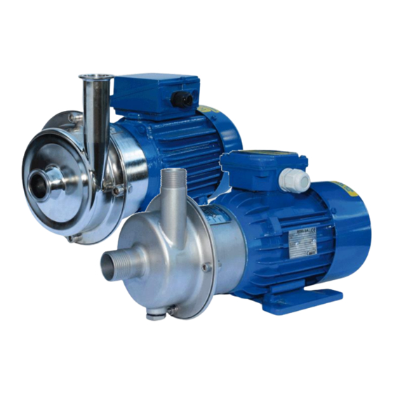
CTI & CTH
Centrifugal Pumps
CTH
With 2900 rpm motor:
CTH AA-03
CTH AA-05
CTH BB-07
CTH CC-15
CTH CC-22
CTH CE-15
CTH CE-22
CTH DD-40
CTH DF-40
CTH DG-40
CTH DF-60
CTH DG-60
CTH EF-55
CTH EG-55
CTH EF-75
CTH EG-75
CTH EG-110B
edition 2018 rev 2
Original instruction
.
CTI
With 1450 rpm motor:
CTI AA-024
CTI BB-054
CTI CC-114
CTI CE-114
CTI DD-224
CTI DF-224
CTI DG-224
CTH
With 1450 rpm motor:
CTH AA-024
CTH BB-054
CTH CC-114
CTH CE-114
CTH DD-224
CTH DF-224
CTH DG-224
Advertisement
Table of Contents

Related Manuals for TapFlo CTI AA-03


Summary of Contents for TapFlo CTI AA-03
- Page 1 Read this instruction manual carefully, before you install and operate the pump With 2900 rpm motor: With 2900 rpm motor: With 1450 rpm motor: With 1450 rpm motor: CTI AA-03 CTH AA-03 CTI AA-024 CTH AA-024 CTI AA-05 CTH AA-05...
-
Page 2: Table Of Contents
CONTENTS GENERAL ............................. 6 0.1. Introduction..........................6 0.2. Warning symbols ........................6 0.3. Qualification and training of personnel ................... 6 INSTALLATION ........................... 7 1.1. Operation principle ........................7 1.2. Receiving inspection ........................7 1.3. Storage ............................7 1.4. Foundation ..........................7 1.5. - Page 3 CONTENTS 2.3.1. Cleaning procedure ......................14 2.4. Residual risks ..........................15 2.5. Disposal after expiration of the expected lifetime ............... 15 2.6. Waste of electrical and electronic equipment (WEEE) directive .......... 15 2.7. Actions in emergency ......................15 MAINTENANCE ..........................16 3.1.
- Page 4 CONTENTS DATA ..............................40 6.1. Pump code ..........................40 6.2. Dimensions - CTI ........................41 6.3. Dimensions - CTH........................42 6.4. Dimensions – CTI long coupled pump ................... 43 6.5. Materials, data and limits ......................44 6.6. Mounting torques and dimensions of screws/nuts .............. 44 6.7.
- Page 5 Member States relating to electrical equipment designed for use within certain voltage limits; Mr Michał Śmigiel is authorized to compile the technical file. Tapflo Sp. z o.o. ul. Czatkowska 4b 83-110 Tczew Signed for and on behalf of Tapflo AB: Håkan Ekstrand Managing director Tapflo AB, 16.04.2016 www.tapflo.com...
-
Page 6: General
The personnel in charge of installation, operation and maintenance of the pumps we produce must be qualified to carry out the operations described in this manual. Tapflo shall not be held responsible for the training level of personnel and for the fact that they are not fully aware of the contents of this manual. -
Page 7: Installation
INSTALLATION INSTALLATION 1.1. Operation principle In order to operate the pump, the casing has to be filled with liquid before start-up. The liquid enters the pump casing axially to the shaft. The rotating impeller generates a centrifugal force accelerating the liquid through the pump casing and into the discharge piping. -
Page 8: Environment
INSTALLATION 1.5. Environment There should be enough space in the vicinity of the pump in order to operate, maintain and repair it. The area in which the pump is operated, must be sufficiently ventilated. Excessive temperature, humidity or dirt may affect the pump operation. ... -
Page 9: Health And Safety
1.7.1. Protection In the interest of health and safety it is essential to wear protective clothing and safety goggles when operating, and/or working in the vicinity of Tapflo pumps. 1.7.2. Electrical safety Do not carry out any maintenance or/and operation on the pump while it is running or before it has been disconnected from the power supply. -
Page 10: Rotating Parts
INSTALLATION 1.7.7. Rotating parts Do not tamper with the protection of the rotating parts, do not touch or approach rotating parts in movement. 1.7.8. Cleaning and disinfection Cleaning and disinfection of the pump system is of greatest importance when the pump is used in a food process installation. -
Page 11: Instruments
INSTALLATION 1.9. Instruments In order to ensure a proper control of the performance and the conditions of the installed pump, we recommend using the following instruments: - a pressure-vacuum gauge on the suction piping; - a pressure gauge on the discharge piping. The pressure intakes must be made of straight pieces of piping at a distance of minimum five diameters from the pump inlets. -
Page 12: Motor Standard
1.11. Motor standard As a standard Tapflo CT pump are equipped with motors of the following parameters: International Mounting Arrangement – B34 Number of poles / Rotation speed [rpm] – 2 ... -
Page 13: Operation
OPERATION OPERATION 2.1. Start-up Check manually that the motor is free to turn, moving the motor cooling fan. Make sure that the piping is not clogged and is free from residues or foreign objects. Make sure that the liquid flows regularly into the pump. ... -
Page 14: Stopping The Pump
OPERATION 2.2. Stopping the pump It is advisable to close the discharge shut-off / regulation valve gradually and stop the motor immediately after. The reverse sequence is not recommendable, especially with larger pumps or longer delivery piping. That is to avoid any problems due to water hammering. If a suction shutoff valve has been installed, it is advisable to close it completely after pump is fully stopped. -
Page 15: Residual Risks
OPERATION 2.4. Residual risks Even with proper application and observance of all points listed in this operating manual, there is still an estimable and unexpected residual risk when using the pumps. It may leak, fail due to wear, application-related causes or system-related circumstances. 2.5. -
Page 16: Maintenance
MAINTENANCE MAINTENANCE Maintenance work on electrical installations must be performed by qualified personnel and only when the power supply has been shutoff. Follow the local and national safety regulations. 3.1. Inspections Periodically check suction and discharge pressures. Inspect the motor according to the instructions from the motor manufacturer. ... -
Page 17: Disassembly Of The Pump
MAINTENANCE 3.3. Disassembly of the pump The disassembly should be performed only by qualified personnel. Each operation to be fulfilled with the machine must always be carried out once all the electrical contacts have been disconnected. The pump-motor unit must be placed in a position where it cannot be started unintentionally. - Page 18 MAINTENANCE Fig 3.3.5 Carefully remove the back casing [12]. The static part [15B] of the mechanical seal will remain in the back casing. Fig 3.3.6 If necessary, push out the static part [15B] of the mechanical seal. NOTE! Apply some alcohol or water before pushing out of the mechanical seal.
-
Page 19: Assembly Of The Pump
MAINTENANCE 3.4. Assembly of the pump The assembly procedure is done in the reverse order to the disassembly. Nevertheless there are a few things that you have to remember in order to assemble the pump correctly. Fig. 3.4.1 Before inserting the static part [15B] of the mechanical seal, fit the back casing [12] onto the back cover [11] and check the seal fitting dimension according to the table below. - Page 20 MAINTENANCE Fig. 3.4.3 – alternative way of assembly „S” dimension can also be set by special Tapflo tool [T]. Put the tool [T] onto the shaft extension [16] and fix it with the screw [191], then lean the tool [T] against internal rim of the back casing [12].
- Page 21 MAINTENANCE Fig. 3.4.7 Simultaneously with both hands push the static part [15B] of mechanical seal until the end. Fig. 3.4.8 Ensure that the static par of mechanical seal is evenly spaced around the circumference. NOTE! Check if O-ring does not springs back. It may springs back when O-ring does not reach the surface of the internal rim.
- Page 22 MAINTENANCE Fig. 3.4.13 Put a few drops of alcohol on the dynamic part O- ring before mounting on shaft extension [16]. Fig. 3.4.14 Evenly pressing, place the dynamic part of the mechanical seal [15A] onto the shaft extension [16]. Fig. 3.4.15 Assembly the spring of the mechanical seal.
-
Page 23: Test Run
MAINTENANCE Fig. 3.4.19 When assembling the casing, make sure that the O- ring sealing surfaces on the casing [13] and the back casing [12] are clean. 3.4.1. Test run We recommend you to conduct a test run of the pump before installing it in the system, so no liquid gets wasted if the pump leaks or perhaps does not start accordingly to wrong assembly of the pump. - Page 24 MAINTENANCE Fig. 3.5.4 Release the metal pipe [1363]. Fig. 3.5.5 Loosen the screw on the elbow union [1367]. Fig. 3.5.6 Remove the metal pipe [1363]. Fig. 3.5.7 Unscrew and remove the elbow union [1367]. Fig. 3.5.8 Unscrew the connection adaptor [1364]. Fig.
- Page 25 MAINTENANCE Fig. 3.5.10 Unscrew the straight union [1366]. Fig. 3.5.11 Unscrew the casing mounting screws [141] and remove them with the nuts [143] and washers [142]. Fig. 3.5.12 Take off the pump casing [136]. Fig. 3.5.13 Remove the O-ring [18]. NOTE! After every disassembly the O-ring [18] has to be replaced by a new one.
-
Page 26: Assembly - 4Fz Option
MAINTENANCE Lubricated seal (4Z) only! Fig. 3.5.16 If necessary remove the lip seal [159]. 3.6. Assembly – 4FZ option The assembly procedure is done in the reverse order to the disassembly. Nevertheless there are a few things that you have to remember in order to assemble the pump correctly. -
Page 27: Options
OPTIONS OPTIONS 4.1. Lubricated seal – 4Z A great option when there is a potential risk of dry running, or where the product tends to solidify or crystallize. An oil reservoir is connected to the mechanical seal chamber. The pump is delivered without lube medium in oil reservoir! ... - Page 28 OPTIONS Additional / different parts: Available for pump sizes: C, D and E Art. no Q-ty Description 5-xxx-1146 Pump back cover for lubricated seal 5-xxx-126 Pump back casing with welded seal chamber 5-xxx-159 Lip seal 5-xxx-16Z Shaft for pump with lubricated seal 5-xxx-16WZ* Shaft –...
-
Page 29: Flushed Seal - 4F (Api Plan 11)
OPTIONS 4.2. Flushed seal – 4F (API Plan 11) When abrasive sticky particles present, it’s recommended to use a flushed seal system. A small amount of the pumped product is recirculated from the discharge side to the seal chamber to flush solids cumulated in it. It helps to save mechanical seal (15) and back casing (12) from being worn. -
Page 30: Heating / Cooling Jacket - 4J
OPTIONS 4.3. Heating / cooling jacket – 4J Great protection for the mechanical seal in cases where there is a risk of solidification of the product. The heating jacket is also used when the pumped product has to maintain a specific temperature, high or low. -
Page 31: Pump Drain - 4K
OPTIONS 4.5. Pump drain – 4K To allow easy draining, the pump casing can be designed with a drain and drain plug. To empty the pump just remove the plug and the casing will drain automatically. As a standard, the drain has a G 3/8” threaded connection. Optional connections like Tri-clamp or hygienic thread can be fitted instead. -
Page 32: Semi-Open Impeller - 4H; Reinforced Impeller - 4W
4.7. Semi-open impeller – 4H; Reinforced impeller – 4W Tapflo CT pumps can be fitted with a semi-open impeller in comparison to its standard open impeller. This option ensures more stable operation, lower noise, lower vibrations and more robust construction. It is recommended to use the semi-open impeller when hard solids can be present in the pumped liquid. -
Page 33: Reinforced Pump Casing - 4B
OPTIONS 4.8. Reinforced pump casing – 4B This option is perfect for CT pumps when the pumped liquid has high penetration properties like paraffin. 4B stands for reinforced front cover which has special groove for O-ring. 4O is for increased number of mounting holes in pump casing, back cover and back casing. -
Page 34: External Quench - 4Q
OPTIONS 4.10. External quench – 4Q This option is similar to the lubricated seal option and is recommended when there is a potential risk of dry running, or where the product tends to solidify or crystallize when in contact with air. There is however an added value to this option, as circulating quench liquid removes heat from the mechanical seal. -
Page 35: Spare Parts
SPARE PARTS SPARE PARTS 5.1. Spare parts drawing 5.2. Spare parts list Size Material Pos. Description CT A CT B CT C CT D CT E CT I CT H AISI 316L Glass AISI 316L Ra<0.8 Back cover [H/N]* blasted AISI 316L Glass AISI 316L Ra<0.8 Back casing [H/N]... -
Page 36: Spare Parts Drawing - Options
SPARE PARTS 5.3. Spare parts drawing - options IOM manual CTI & CTH centrifugal pumps... -
Page 37: Spare Parts List - Options
SPARE PARTS 5.4. Spare parts list - options Lubricated seal – 4Z Hygienic shroud - M Art. no Q-ty Description Art. no Q-ty Description 5-xxx-1146 Pump back cover for lubricated seal 5-xxx-31 Hygienic pump shroud Pump back casing with welded seal 5-xxx-34 Shroud foot 5-xxx-126... -
Page 38: Spare Parts - Long Coupled Execution
SPARE PARTS 5.5. Spare parts – long coupled execution 5.6. Spare parts list – long coupled execution Pos. Description Q-ty Material Back cover AISI 316L Back casing AISI 316L 1210 Back cover mounting screws A4-70 Back cover mounting washer A4-70 Back cover mounting nut A4-70 Pump casing... -
Page 39: Recommended Spare Parts
5.8. How to order parts When ordering spare parts for Tapflo pumps. please let us know what is the model number and serial number from the pump’s name plate. Then just indicate the part numbers from the spare parts list and quantity of each item. -
Page 40: Data
II. Pump execution VI. Motor power III. Casing size VII. Motor option IV. Impeller size 1CGV3F- CT = Tapflo centrifugal pump = Thread RJT (CTH only) Pump execution: = ISO 1127 clamp (CTH only) = Industrial = DIN11866-1A thread (CTH only) -
Page 41: Dimensions - Cti
Dimensions - CTI Dimensions in mm (where other is not indicated) General dimensions only, ask us for detailed drawings. Changes reserved without notice. Motor Weight MODEL [kg] power size CTI AA-03 0.37 7.15 CTI AA-05 0.55 8.00 CTI BB-07 0.75 11.40 CTI CC-15 22.25... -
Page 42: Dimensions - Cth
DATA 6.3. Dimensions - CTH Dimensions in mm (where other is not indicated) General dimensions only, ask us for detailed drawings. Changes reserved without notice. Motor Weight MODEL [kg] power size 7.35 0.37 CTH AA-03 8.00 0.55 CTH AA-05 11.40 0.75 CTH BB-07 22.35... -
Page 43: Dimensions - Cti Long Coupled Pump
DATA 6.4. Dimensions – CTI long coupled pump Dimensions in mm (where other is not indicated) General dimensions only, ask us for detailed drawings. Changes reserved without notice. Motor Weight MODEL power size [kg] 0.37 CTI AA-03B 0.55 CTI AA-05B 0.25 CTI AA-024B 0.75... -
Page 44: Materials, Data And Limits
DATA 6.5. Materials, data and limits CTH … CTI … Casing Stainless steel AISI 316L electro polished Ra<0.8 Stainless steel AISI 316L glass blasted Stainless steel AISI 316L electro polished Ra<0.8, Stainless steel AISI 316L electro polished Ra<0.8, Impeller open (std) or semi-open open (std) or semi-open Single ceramic/graphite (std), SiC/SiC or Single ceramic/graphite (std), SiC/SiC or... -
Page 45: Performance Curves
DATA 6.7. Performance curves The performance curves are based on water at 20°C. Contact us for detailed curves Speed 2900 rpm Speed 1450 rpm IOM manual CTI & CTH centrifugal pumps... -
Page 46: Permitted Loads On Inlet And Outlet
DATA 6.8. Permitted loads on inlet and outlet We recommend not to exceed the following loads and forces reacting on the inlet and CT A Load [N] Moment of force Direction (inlet/outlet) (inlet/outlet) [Nm] CTI B Load [N] Moment of force Direction (inlet/outlet) (inlet/outlet) [Nm]... -
Page 47: Warranty
7.2. Warranty Tapflo warrants products under conditions as stated below for a period of not more than 12 months from installation and not more than 24 months from date of manufacturing. 1. The following terms and conditions apply to the sale of machinery, components and related services and products, of Tapflo (hereinafter “the products”). - Page 48 9. Tapflo will not be liable on any claim, whether in contact, tort, or otherwise, for any indirect, special, incidental or consequential damages caused to the customer or to third parties, including loss of profits arising by any possible infringement of par.
-
Page 49: Warranty Form
WARRANTY 7.3. Warranty form Company: Telephone: Fax: Address: Country: Contact Name: E-mail: Delivery Date: Date of pump installation: Pump type: Serial No (see name plate): Description of the fault: The installation: Liquid: Temperature [°C]: Viscosity [cPs]: Spec grav. [kg/m pH-value: Content of particles: %, of max size [mm]: Flow [l/min]:... - Page 50 Tech support: support@tapflo.com Tapflo products and services are available in 75 countries on 6 continents. Tapflo is represented worldwide by own Tapflo Group Companies and carefully selected distributors assuring highest Tapflo service quality for our customers’ convenience. AUSTRALIA | AUSTRIA | AZERBAIJAN | BAHRAIN | BELARUS | BELGIUM | BOSNIA & HERZEGOVINA | BRAZIL | BULGARIA |...
Need help?
Do you have a question about the CTI AA-03 and is the answer not in the manual?
Questions and answers