Table of Contents

Related Manuals for TapFlo T/TX30


Summary of Contents for TapFlo T/TX30
- Page 1 IOM manual Sanitary Series Diaphragm Pumps Original Instruction 2020 | 1 edition 2019 rev 1 Read this instruction manual carefully, before you install and operate the pump Pump models: T/TX30 T/TX80 T/TX125 T/TX225 T/TX425 T/TX825...
-
Page 2: Table Of Contents
CONTENTS GENERAL ............................7 0.1. Introduction..........................7 0.2. Warning symbols ........................7 0.3. Qualification and training of personnel ................... 7 INSTALLATION ..........................8 1.1. Operation principle ........................8 1.2. Receiving inspection ........................8 1.3. Lifting and transportation ......................9 1.4. Storage ............................ - Page 3 CONTENTS 2.5. Residual risks ..........................17 2.6. Disposal after expiration of the expected lifetime ............... 17 2.7. Actions in emergency ......................17 MAINTENANCE ..........................18 3.1. When the pump is new or reassembled ................. 18 3.1.1. Performance test ......................18 3.2.
- Page 4 CONTENTS 5.6. T225-T425 – Spare parts drawing ................... 46 5.7. T225-T425 – Spare parts list ....................47 5.8. T225 – T425 – Spare parts options ..................48 5.9. T825 – Spare parts drawing ....................51 5.10. T825 – Spare parts list ......................52 5.11.
- Page 5 Directive 2006/42/EC of European Parliament and of the Council of 17 May 2006 on • machinery, amending Directive 95/16/EC; Mr Michał Śmigiel is authorized to compile the technical file. Tapflo Sp. z o.o. ul. Czatkowska 4b 83-110 Tczew Signed for and on behalf of Tapflo AB Håkan Ekstrand Managing director Kungälv, 28.10.2020 www.tapflo.com...
- Page 6 II 2D Ex h IIIC T60ºC…T125ºC Db Notified body J.S. Hamilton Poland Sp. z o.o. (2057) performed EU-type examination and issued certificate JSHP 19 ATEX 0018X. Signed for and on behalf of Tapflo AB Håkan Ekstrand Managing Director Kungälv, 28.10.2020...
-
Page 7: General
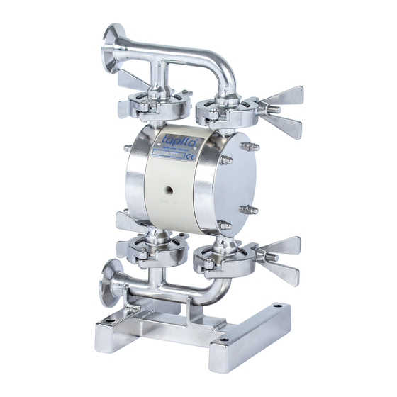
0.1. Introduction The Tapflo Air Operated Diaphragm Pump range is a complete series of pumps for industrial applications. The pumps are designed to be safe, simple and easy to use and maintain. The construction is seal-less and without rotating parts. The pumps are suitable for a variety of duties in hygienic installations. -
Page 8: Installation
1.1. Operation principle The Tapflo diaphragm pump is driven by compressed air. The two diaphragms are connected by a diaphragm shaft and pushed back and forth by alternately pressurising the air chambers behind the diaphragms using an automatically cycling air valve system. -
Page 9: Lifting And Transportation
INSTALLATION 1.3. Lifting and transportation Before handling the pump check the weight of the pump (see 6.4. Technical data). Refer to Your local standards on how to handle the pump. If the weight is excessive to transport by hand it must be lifted using slings and a suitable lifting device e.g. a crane or forklift. Always use at least two slings and make sure they are secured in such a way to prevent the pump from slipping and that the pump unit is hanging straight. -
Page 10: Connection Of Suction Pipe
1.7.1. Protection In the interest of health and safety it is essential to wear protective clothing and safety goggles when operating, and/or working in the vicinity of Tapflo pumps. IOM manual - Sanitary series... -
Page 11: Explosion Hazardous Environments - Atex
125°C T4 - 135°C If ambient temperature exceeds the range -20°C ≤ Ta ≤ +40°C, contact Tapflo. Earth connection of the pump and other equipment Connect a suitable earth wire to the stainless steel earth connection that is placed on the inside of one of the pump housings. -
Page 12: Air Pressure
1.7.3. Air pressure The maximum air pressure for Tapflo pumps is 8 bar. Higher air pressure than 8 bar can damage the pump and may cause injury to personnel in vicinity of the pump. If you intend to apply a higher air pressure than 8 bar, please consult us. -
Page 13: Air Treatment System
3) Needle valve to adjust the air flow (especially when operating the pump in the lower range of performance); 4) Filter. These components are included in Tapflo’s Air treatment system which can be ordered from Air quality classes 1.8.2. ISO 8573-1:2010 Compressed Air Contaminants and Purity Classes... -
Page 14: Installation Example
1.10.2. Self-priming The Tapflo pump is designed to pull a high vacuum. It is able to evacuate an empty suction pipe without any damage to the pump. The suction lift is up to 5 meters (16.4 ft.) from an empty suction pipe and up to 8 meters (26.2 ft.) from a wetted pipe. The suction capability depends on the pump size (see chapter 6. -
Page 15: Operation
For instance, a T80 pump should run continuous at maximum 40 l/min. ➢ As stated in chapter 1.8.1 Tapflo recommends to use an appropriate air treatment system in order to extend the pump’s lifetime. -
Page 16: Pump Stopping
2.4.1. CIP – Cleaning In Place The importance of easy cleaning is essential in hygienic applications. Tapflo aseptic pumps are designed for CIP (Cleaning In Place) and SIP (Sterilization In Place). This allows the pump to be internally cleaned without disassembly. The pump can be cleaned by flushing through with a CIP fluid (usually a mild solution of sodium hydroxide and a sanitizing additive) or by injection of hot steam (SIP). -
Page 17: Drainage Of The Pump (T80 - T825)
2.4.1.1. Drainage of the pump (T80 – T825) After the CIP procedure, the pump usually has to be drained from the CIP fluid. The Tapflo sanitary series is supplied with a hygienic stand, enabling 360° rotation of the pump unit. -
Page 18: Maintenance
The characteristics of the liquid, temperature, materials used in the pump and running time decide how often a complete inspection is necessary. Nevertheless, Tapflo recommend to inspect the pump at least once a year and change parts from KIT AIR and KIT LIQ during this inspection. See chapter x.x “Stocking recommendation”... -
Page 19: Location Of Faults
MAINTENANCE 3.4. Location of faults PROBLEM POSSIBLE FAULT POSSIBLE SOLUTION The air pressure is to low Increase air pressure via a filter-regulator The air connection is blocked Check / clean air supply connection Muffler is blocked Check / clean / replace muffler The pump does not run Air valve is defective Clean / replace complete air valve... -
Page 20: T30 - Disassembly Of The Pump
MAINTENANCE 3.5. T30 – Disassembly of the pump The numbers put in brackets, refer to the part numbers in the spare part drawings and spare part lists in chapter 5 “SPARE PARTS”. 3.5.1. Before the disassembly procedure Be sure to drain all liquid from the pump. Cleanse or neutralize the pump thoroughly. Disconnect the air supply and then the suction and discharge connections. - Page 21 MAINTENANCE Fig. 3.5.3c Fig. 3.5.4 Remove the sealing [18]. Unscrew and remove two tri-clamps [138] connecting the inlet manifold and stand [131] to the housings [11]. Fig. 3.5.5 Fig. 3.5.6 Take the centre block [12] and housing [11] Remove the valve balls [23] and sealing [18]. assembly of the inlet manifold and stand.
- Page 22 MAINTENANCE Fig. 3.5.9 Fig. 3.5.10 Remove the domed nuts [37], stud bolts [14] and Take off the second housing [11]. washers [38]. Fig 3.5.12 Fig 3.5.11 Take out the second diaphragm [15] along with the Unscrew the diaphragm [15]. shaft [16]. Fig 3.5.13 Fig 3.5.14 Using circlip pliers remove both circlips [27] from the...
-
Page 23: T30 - Assembly Of The Pump
MAINTENANCE The pump is now completely disassembled. Check all components for wear or damage and replace if necessary. When air valve is removed from the centre body check the external O-rings ( pos. 30) condition and replace if necessary. 3.6. T30 –... -
Page 24: Test Run
MAINTENANCE Fig. 3.6.6 Fig. 3.6.5 When fastening the tri-clamps apply some FDA When fastening the domed nuts, remember to do it grade lubricant on the thread. with correct order and with the appropriate torque. NOTE! Keep in mind to periodically retighten stud bolt’s nuts. -
Page 25: T80-T425 - Disassembly Of The Pump
MAINTENANCE 3.7. T80-T425 – Disassembly of the pump The numbers put in brackets, refer to the part numbers in the spare part drawings and spare part lists in chapter 5 “SPARE PARTS”. 3.7.1. Before the disassembly procedure Be sure to drain all liquid from the pump. Cleanse or neutralize the pump thoroughly. Disconnect the air supply and then the suction and discharge connections. - Page 26 MAINTENANCE Fig. 3.7.2b Fig. 3.7.2c Remove the valve balls [23]. Remove the sealing [18]. Fig. 3.7.3 Fig. 3.7.4 Loosen the socket head cup screws [174] and rotate Remove the socket head cap screws [174] and take the pump, after that repeat the steps shown in the off the pump from the stand [17].
- Page 27 MAINTENANCE Fig. 3.7.7 Fig. 3.7.8 Remove the domed nuts [37], stud bolts [14] and Take off the second housing [11]. washers [38]. Fig. 3.7.9 Fig. 3.7.10 Unscrew the diaphragm [15] from one side of the Take out the second diaphragm [15] along with the pump.
- Page 28 MAINTENANCE b) Plate mounted air valve – TX125 from s/n 0907-…, T/TX225, T/TX425 Fig. 3.7.13 Fig. 3.7.14 Unscrew plate screws [2711] from both sides of the Press out the air valve [61] by means of a pressing centre body [12] and take out the left and right device.
-
Page 29: T80-T425 - Assembly Of The Pump
MAINTENANCE 3.8. T80-T425 – assembly of the pump The assembly procedure is done in the reverse order to the disassembly. Nevertheless there are a few things that you have to remember in order to assemble the pump correctly. Fig. 3.8.1 When putting the air valve [61] into the centre block Fig. -
Page 30: Test Run
MAINTENANCE Fig. 3.8.4b Fig. 3.8.5 8 stud bolts. When fastening the domed nuts, When fastening the tri-clamps apply some FDA remember to do it according to the tightening grade lubricant on the thread. procedure and with the appropriate torque. 3.8.1. Test run We recommend you to conduct a test run of the pump before installing it in the system, so no liquid gets wasted if the pump leaks or perhaps does not start accordingly to wrong assembly of the... -
Page 31: T825 - Disassembly Of The Pump
MAINTENANCE 3.9. T825 – Disassembly of the pump The numbers put in brackets, refer to the part numbers in the spare part drawings and spare part lists in chapter 5 “SPARE PARTS”. 3.9.1. Before the disassembly procedure Be sure to drain all liquid from the pump. Cleanse or neutralize the pump thoroughly. Disconnect the air supply and then the suction and discharge connections. - Page 32 MAINTENANCE Fig. 3.9.4 Fig. 3.9.3 Remove the blocking pin [176] and loose the socket Repeat the steps shown in the figures 3.9.1 and 3.9.2 head cap screws [174], then take off the pump from a, b, c for suction side. the stand [17].
- Page 33 MAINTENANCE Fig. 3.9.9 Fig. 3.9.10 Unscrew the diaphragm [15] from one side of the Take out the second diaphragm [15] along with the pump. shaft [16]. Pressing device Fig. 3.9.11 Fig. 3.9.12 Using circlip pliers remove both circlips [27] from Press out the air valve [61] by means of a pressing the centre block [12].
-
Page 34: T825 - Assembly Of The Pump
MAINTENANCE 3.10. T825 – assembly of the pump The assembly procedure is done in the reverse order to the disassembly. Nevertheless there are a few things that you have to remember in order to assemble the pump correctly. Fig. 3.10.1 Fig. -
Page 35: Test Run
MAINTENANCE Fig. 3.10.4b When fastening the tri-clamps apply some FDA grade lubricant on the thread. 3.10.1. Test run We recommend you to conduct a test run of the pump before installing it in the system, so no liquid gets wasted if the pump leaks or perhaps does not start accordingly to wrong assembly of the pump. -
Page 36: Options
OPTIONS OPTIONS 4.1. Valve options In pump sizes T80 - T425 flap valves and heavy duty ball cup valves are available as an option to standard ball valves. What is more, T825 pump size can also be configured with flap valves. -
Page 37: Ball Cup Valves
OPTIONS 4.1.2. Ball cup valves This option is a perfect solution when there is risk of damage to the valve seats from the product. If such situation is to occur there is no need to replace the whole manifolds or housings, just the valve cup what drastically reduces the spare parts cost. -
Page 38: Magnetic Ball Lifters
OPTIONS 4.3. Magnetic ball lifters New magnetic ball lifters have been implemented in pump sizes T80 - T225. They are implemented to enable pump emptying when no other draining option is available. Rotating the pump is no longer needed. The balls are lifted by simply attaching the magnets to the pumps manifold. Valve balls are available in AISI 420 magnetic stainless steel or PTFE wits steel core. -
Page 39: Spare Parts
SPARE PARTS SPARE PARTS 5.1. T30 – Spare parts drawing IOM manual - Sanitary series... -
Page 40: T30 - Spare Parts List
SPARE PARTS 5.2. T30 – Spare parts list Pos. Q-ty Description Material Housing AISI 316L Centre block PP, Conductive PP Manifold inlet and stand AISI 316L Manifold outlet AISI 316L 3-clamp AISI 304 Stud bolt A4-80 EPDM, PTFE, NBR, PTFE/White EPDM, Diaphragm white EPDM Diaphragm shaft... -
Page 41: T80-T125 - Spare Parts Drawing
SPARE PARTS 5.3. T80-T125 – Spare parts drawing IOM manual - Sanitary series... -
Page 42: T80-T125 - Spare Parts List
SPARE PARTS 5.4. T80-T125 – Spare parts list Pos. Q-ty Description Material Housing AISI 316L Centre block PP, PP Conductive Manifold inlet AISI 316L Manifold outlet AISI 316L 3-clamp AISI 304 Stud bolt A4-80 EPDM, PTFE, NBR, PTFE/White EPDM, Diaphragm white EPDM Diaphragm shaft AISI 304L... -
Page 43: T80 - T125 - Spare Parts Options
SPARE PARTS 5.5. T80 – T125 – Spare parts options 2711 Diaphragm stroke sensor 5C Air valve reinforcement 5TS (T125 only) – std on Centerblock for stroke TX125 sensor PP, PP NBR, FKM, Center block O-ring Cond. EPDM Set of 2 reinforcement Inductive sensor CuZn AISI 316L... - Page 44 SPARE PARTS External air supply 5EC Center block PP, PP Cond. Air intake adapter Brass 132F 181F alve ball cup set 1381 241B 131F Ball cup valves 5SC Housing AISI316L Manifold inlet 131F AISI316L Manifold outlet 132F AISI316L Tri-clamp 1381 AISI304 Stand AISI304...
- Page 45 SPARE PARTS 132F 1 1 F Hou sin g 1 3 1 F M a n ifold in le 1 3 2 F M a n ifold ou tl Tri clamp 1 3 8 1 S ta n d 181F Flap valve set 1 8 F S e a lin g...
-
Page 46: T225-T425 - Spare Parts Drawing
SPARE PARTS 5.6. T225-T425 – Spare parts drawing IOM manual - Sanitary series... -
Page 47: T225-T425 - Spare Parts List
SPARE PARTS 5.7. T225-T425 – Spare parts list Pos. Q-ty Description Material KIT LIQ KIT AIR Housing AISI 316L Centre block PP, PP Conductive Manifold inlet AISI 316L Manifold outlet AISI 316L 3-clamp AISI 304 Stud bolt A4-80 EPDM, PTFE, NBR, PTFE/White Diaphragm... -
Page 48: T225 - T425 - Spare Parts Options
SPARE PARTS 5.8. T225 – T425 – Spare parts options Magnetic ball lifters 5ML Diaphragm stroke sensor 5C Centerblock for stroke 23-15 Valve ball PTFE/SS core sensor Valve ball 23-59 AISI420 NBR, FKM, Magnetic ball lifter PE1000 O-ring EPDM Holder AISI316L Inductive sensor CuZn... - Page 49 SPARE PARTS 132F 181F alve ball cup set 241B 131F Ball cup valves 5SC Housing AISI316L Inlet manifold 131C AISI316L Tri-clamp AISI304 Stand AISI304 Sealing PTFE, EPDM Stopper O-ring FEP/FKM Valve ball stopper AISI316L Ball valve cup 241B AISI316L Ball valve cup set 6-425-24B-x-SET x - valve ball material.
- Page 50 SPARE PARTS 132F 181F Flap valve set 241F 242F 131F Flap valves Housing AISI316L Inlet manifold 131F AISI316L Outlet manifold 132F AISI316L Stand AISI304 Sealing 181F PTFE, EPDM Sealing PTFE, EPDM Tri-clamp AISI304 Flap valve seat 241F AISI316L Flap 242F AISI316L Flap valve set 6-425-24F-SET...
-
Page 51: T825 - Spare Parts Drawing
SPARE PARTS 5.9. T825 – Spare parts drawing 1791 1792 IOM manual - Sanitary series... -
Page 52: T825 - Spare Parts List
SPARE PARTS 5.10. T825 – Spare parts list Pos. Description Material Q-ty Housing AISI 316L Centre block PP, PE1000 conductive Manifold inlet AISI 316L Manifold outlet AISI 316L 3-clamp AISI 304 Stud bolt A4-80 Diaphragm EPDM, PTFE, NBR Shaft set AISI 304L Stand AISI 304... -
Page 53: T825 - Spare Parts Options
SPARE PARTS 5.11. T825 – Spare parts options 2711 138H 242H Air valve reinforcement 5TS 243H Center block Set of 2 reinforcement AISI 316L plates Screws 2711 A4-70 243H Flap valves Housing AISI316L In/outlet manifold AISI316L Tri-clamp (DN100) AISI304L Tri-clamp (DN150) 138H AISI304L Stand... -
Page 54: Stocking Recommendation
5.13. How to order parts When ordering spare parts for Tapflo pumps, please let us know what is the model number and serial number from the pump centre body. Then just indicate the part numbers from the spare parts list and quantity of each item. -
Page 55: Pump Code
III. Max capacity [l/min] VI. Material of valve balls VII. Special executions S T T -7PV T = Tapflo diaphragm pump VI. Material of valve balls: = EPDM II. Basic options: N = NBR (nitrile rubber) B = Backup diaphragm pump... -
Page 56: Data
DATA DATA 6.1. Capacity curves The performance curves are based on water at 20°C.Other circumstances might change the performance. See below how the capacity will change at different viscosities and suction lifts. Example: A flow of 30 litre/minute is desired. The discharge pressure is calculated to 25 mWC. We choose a T80 pump. -
Page 57: Capacity Changes
DATA 6.2. Capacity changes Capacity changes at different suction lifts Capacity changes at different viscosities 6.3. Dimensions Dimensions in mm (where other is not indicated) Dimensions in inch (where other is not indicated) General dimensions only, ask us for detailed drawings. Changes reserved without notice. PUMP SIZE Dimension T825... - Page 58 DATA IOM manual - Sanitary series...
-
Page 59: Technical Data
What is more for proper operation and safety the torque values should be checked frequently as part of preventive maintenance (contact Tapflo for interval proposals). Although pump applications vary, a general guideline is to re-torque the pump every two weeks. - Page 60 DATA We recommend not to exceed the following loads and forces reacting on the manifolds. T825 Load [N] Moment of force Load [N] Moment of force Direction Direction (inlet/outlet) (inlet/outlet) [Nm] (inlet/outlet) (inlet/outlet) [Nm] 16,2 13,2 16,2 13,2 16,2 13,2 Load [N] Moment of force Direction...
-
Page 61: Warranty
WARRANTY WARRANTY 7.1. Warranty form Company: Telephone: Fax: Address: Country: Contact Name: E-mail: Delivery Date: Date of pump installation: Pump type: Serial No (see name plate or stamped on pump housing): Description of the fault: The installation: Liquid: Temperature [°C]: Viscosity [cPs]: Spec grav. -
Page 62: Returning Parts
7.3. Warranty Tapflo warrants products under conditions as stated below for a period of not more than 5 years from installation and not more than 6 years from date of manufacturing. 1. The following terms and conditions apply to the sale of machinery, components and related services and products, of Tapflo (hereinafter “the products”). - Page 63 9. Tapflo will not be liable on any claim, whether in contact, tort, or otherwise, for any indirect, special, incidental, or consequential damages, caused to the customer or to third parties, including loss of profits, arising by any possible infringement of par.
Need help?
Do you have a question about the T/TX30 and is the answer not in the manual?
Questions and answers