Table of Contents
Advertisement
IOM manual
2012 rev 2
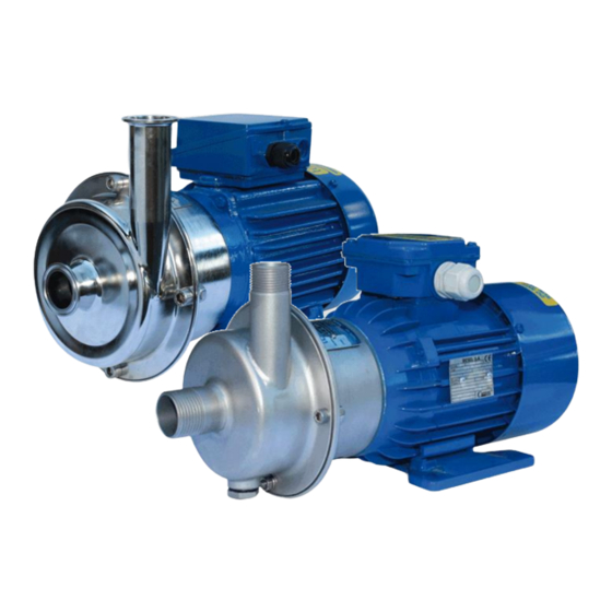
Pumps CTH in electro polished stainless steel AISI 316L.
Pumps CTI in glass blasted stainless steel AISI 316L.
Instructions for installation, start up, operation, maintenance and repair.
Pump models:
CTI
With motor 2900 rpm:
CTI AA-03
7 m
/h, 10 m
3
CTI AA-05
12 m
/h, 10 m
3
CTI BB-07
17 m
3
/h, 11 m
CTI CC-15
19 m
/h, 22 m
3
CTI CC-22
34 m
/h, 22 m
3
CTI CE-22
20 m
/h, 31 m
3
CTI DD-40
50 m
/h, 22 m
3
CTI DF-40
28 m
3
/h, 35 m
CTI EF-55
42 m
/h, 35 m
3
CTI EG-55
30 m
/h, 47 m
3
CTI EF-75
60 m
/h, 35 m
3
CTI EG-75
35 m
/h, 47 m
3
CTI EG-110B
50 m
/h, 32 m*
3
With motor 1450 rpm:
CTI AA-024
7 m
/h, 2.7 m
3
CTI BB-054
9 m
/h, 2.8 m
3
CTI CC-114
18 m
/h, 5.5 m
3
CTI CE-114
22 m
/h, 7.7 m
3
CTI DD-224
25 m
/h, 5.5 m
3
CTI DF-224
34 m
/h, 8.7 m
3
CTI DG-224
42 m
/h, 12.0 m
3
*only in long coupled pump execution
Read this instruction manual carefully,
STOP
before you install and operate the pump
CTH
With motor 2900 rpm:
CTH AA-03
7 m
/h, 10 m
3
CTH AA-05
12 m
/h, 10 m
3
CTH BB-07
17 m
3
/h, 11 m
CTH CC-15
19 m
/h, 22 m
3
CTH CC-22
34 m
/h, 22 m
3
CTH CE-22
20 m
/h, 31 m
3
CTH DD-40
50 m
/h, 22 m
3
CTH DF-40
28 m
3
/h, 35 m
CTH EF-55
42 m
/h, 35 m
3
CTH EG-55
30 m
/h, 47 m
3
CTH EF-75
60 m
/h, 35 m
3
CTH EG-75
35 m
/h, 47 m
3
CTH EG-110B
50 m
/h, 32 m*
3
With motor1450 rpm:
CTH AA-024
7 m
/h, 2.7 m
3
CTH BB-054
9 m
/h, 2.8 m
3
CTH CC-114
18 m
/h, 5.5 m
3
CTH CE-114
22 m
/h, 7.7 m
3
CTH DD-224
25 m
/h, 5.5 m
3
CTH DF-224
34 m
/h, 8.7 m
3
CTH DG-224
42 m
/h, 12.0 m
3
www.51085793.com
Advertisement
Table of Contents

Related Manuals for TapFlo CTI AA-03


Summary of Contents for TapFlo CTI AA-03
- Page 1 Pumps CTI in glass blasted stainless steel AISI 316L. Instructions for installation, start up, operation, maintenance and repair. Pump models: With motor 2900 rpm: With motor 2900 rpm: CTI AA-03 /h, 10 m CTH AA-03 /h, 10 m CTI AA-05 12 m /h, 10 m...
-
Page 2: Table Of Contents
CONTENTS Chapter Content Page Contents CE certificate General Introduction The warning symbols Qualification and training of personnel Health & safety Installation Receiving inspection Storage Foundation Piping connections 1.4.1 Discharge pipe 1.4.2 Suction pipe Example of installation Instruments Motor connection Operation Start-up 2.1.1 Starting the pump... -
Page 3: Ce Certificate
EC Machinery directive 2006/42/EC with amendments 91/368/EEC, 93/94 EEC and 93/68 EEC. Manufacturer: Tapflo AB Address: Filaregatan 4 S-442 34 Kungälv Sweden Tapflo AB, may 2:nd 2012 Håkan Ekstrand Managing director Instruction manual CT centrifugal pumps... -
Page 4: General
STOP must be qualified to carry out the operations described in this manual. Tapflo shall not be held respon- sible for the training level of personnel and for the fact that they are not fully aware of the contents of this manual. -
Page 5: Health & Safety
GENERAL Health & safety Electric safety Do not carry out any maintenance operation on the pump while it is running or before it has been dis- connected from the power supply. Avoid any danger caused by electric power (for details see current regulations in force). -
Page 6: Installation
INSTALLATION Receiving inspection Although precaution is taken by us when packing and shipping, we urge you to carefully check the ship- ment on receipt. Make sure that all parts and accessories listed on the packing list are accounted for. Immediately report any damage or shortage to the transport company and to us. Storage If the equipment is to be stored prior to installation, place it in a clean location. -
Page 7: Example Of Installation
INSTALLATION Example of installation Fig. 1 Installation 1) YES: gate valve (may also be near pump in the case of long piping) 2) With positive head: tilt of piping towards pump 3) YES: line strainer if particles are present 4) NO: air pockets: the circuit must be short and straight 5) YES: pipe fixing parts 6) Suction line as short and direct as possible 7) YES: check valve (especially for long vertical or horizontal pipes;... -
Page 8: Instruments
INSTALLATION Instruments In order to ensure a reasonable control of the performance and the conditions of the pump installed, we recommend using the following instruments: a pressure-vacuum gauge on the suction piping; a pressure gauge on the delivery piping. The pressure intakes must be made on straight pieces of piping at minimum five diameters from the pump inlets. -
Page 9: Operation
OPERATION Start-up Check manually that the motor is free to turn, moving the motor cooling fan. Make sure that the piping is not clogged and is free from residues or foreign objects. Make sure that the liquid flows regularly into the pump. The pump and piping connected to it, at least the suction pipe, must be full of liquid. -
Page 10: Cleaning And Disinfection
OPERATION Cleaning and disinfection Cleaning and disinfection of the pump system is of greatest importance when the pump is used in a food STOP process installation. Use of a pump system that is NOT cleaned or disinfected can cause contamination of the product. -
Page 11: Maintenance
MAINTENANCE Maintenance work on electrical installations must be performed by qualified personnel and only when the power supply has been shutoff. Follow the local and national safety regulations. Inspections Periodically check suction and discharge pressures. Inspect the motor according to the instructions from the motor manufacturer. In general, a mechanical seal does not require maintenance, but the pump should never run when empty (dry). -
Page 12: Assembly And Disassembly
MAINTENANCE Assembly and disassembly The assembly and disassembly should only be performed by qualified personnel. Each operation carried out on the machine must always be carried out once all the electrical contacts have been disconnected. The pump-motor unit must be placed in a position where it cannot be started unintentionally. -
Page 13: Impeller And Back Casing - Disassembly
MAINTENANCE 3.3.2 Impeller (90) and back casing (12) – disassembly Disassemble the pump casing (13) according to chapter 3.3.1 Remove the impeller mounting screw (191) and the washer (192), use spanner key on the cut in pump shaft (pos. 16) to lock the impeller - Fig 6. Remove the impeller (90). -
Page 14: Assembly Of Impeller
MAINTENANCE Assembly Before assembly, wet the O-rings on the seal with soapy water. Carefully insert the static part of the seal (15B) in the back casing - Fig 12. Fit the back casing (12) onto the back cover (11) - Fig 13. Check the seal fitting dimensions according to table 3.3.3 to ensure the correct pressure on the seal. -
Page 15: Replacement Of Motor
MAINTENANCE 3.3.5 Replacement of motor (1) Follow the instructions for disassembly of the impeller and back casing according to chapter 3.3.2. Remove the deflector (17) from the shaft extension (16) - Fig 18. Remove the back cover screws (121) and washers (122) - Fig 19. Remove the back cover (11). -
Page 16: Lubricated Seal
MAINTENANCE Lubricated seal A great option where there is a potential risk of dry running, or where the product tends to solidify or crystallize. An oil chamber is connected to the mechanical seal chamber. The pump is delivered without lube medium in oil chamber! - Before the first start fill up the oil chamber with proper medium (i.e. -
Page 17: Heating Jacket
A heating or cooling medium is continuously circulated in the jacket. Back casing heating/cooling system is available in sizes: “C” , “D” and "E" of Tapflo CT pumps. Heating/cooling is operated by a jacket placed in pump back casing (12). The jacket have two G ½”... - Page 18 MAINTENANCE To meet the demands from a variety of today’s industry we also provide options that are a combination of executions listed above such as: Flushed and oil lubricated seal with heating jacket. Additional parts: Description 11146 Pump back cover for flushed and oil lubricated seal with heating jacket Joint for pump with heating jacket 1260 Pump back casing with welded seal chamber and heating jacket...
-
Page 19: Hygienic Shroud
MAINTENANCE Hygienic shroud Optional motor shroud and baseplate in stainless steel provide easy cleaning and splash protection for electrical motor. To protect electric motor from liquids and to keep an pump application clean, the hygienic shroud design contains additional parts as follow: Description Hygienic cover for motor Shroud foot... -
Page 20: Technical Data
Technical data Spare part drawing CT pumps Fig. 30. Spare part list Description Pump model / quantity Material AA-03 BB-07 CC- 1 5 DD-40 DG-55 EF-55 AA-05 BB-04 CC-22 DG-55 EG-55 A A - CE-22 EF-75 DF-40 EG-75 CE-144 Electric motor Back cover [H/N]* AISI 316L Glass blasted AISI 316L Ra<0.8... -
Page 21: Spare Part List Cti
2” 2” 1/2” 1/2” * = NPT thread available as option General dimensions Model Motor IEC motor power (kW) size CTI AA-03 0.37 CTI AA-05 0.55 CTI BB-07 0.75 CTI CC-15 CTI CC-22 CTI CE-22 CTI DD-40 CTI DF-40 CTI EF-55... -
Page 22: Spare Part List Cth
TECHNICAL DATA Connection dimensions Connection Model CTH type DIN 11851 thread (standard) DIN 32676 clamp ISO 2852 clamp Ra 21.3 25 SMS thread RJT thread 2” 3” 3” 1/2” 1/2” 1” 2” 2” 2” 1/2” General dimensions Model Motor IEC motor power (kW) size CTH AA-03... -
Page 23: Stocking Recommendation
2. Pump version 6. Motor power 3. Casing size 7. Motor options 4. Impeller size 1CGV3F- 02 CT = Tapflo centrifugal pump 3. Connection options Blank* = Thread BSP on CTI Pump version Thread DIN 11851 on CTH = Industrial version... -
Page 24: Data
DATA Performance curves The performance curves are based on water at 20°C. Contact us for detailed curves. Speed 2900 rpm CTDG CTEG CTDF CTDF CTCE CTEF CTEF CTCC CTDD CTAA CTBB Speed 1450 rpm CTDG CTDF CTCE CTDD CTCC CTAA CTBB Changes reserved without notice Instruction manual CT centrifugal pumps... -
Page 25: Warranty & Repair
Goods will not be accepted unless the above procedure has been complied with. Warranty Tapflo warrants products under conditions as below for a period of not more than 12 months from instal- lation and not more than 24 months from date of manufacture. - Page 26 9 Tapflo will not be liable on any claim, whether in contact, tort, or otherwise, for any indirect, special, incidental, or consequential damages, caused to the customer or to third parties, including loss of profits, arising by any possible infringement of par.
-
Page 27: Warranty Form
WARRANTY Warranty form Company: Telephone: Fax: Address: Country: Contact name: E-mail: Delivery date: Pump was installed (date): Pump type: Serial No (see name plate): Description of the fault: The installation Liquid: Temperature (°C): Viscosity (cPs): Spec. grav. (kg/m pH-value: Contents of particles: %, of max size (mm): Flow (l/min): Duty (h/day):...
Need help?
Do you have a question about the CTI AA-03 and is the answer not in the manual?
Questions and answers