TapFlo T30 Manual
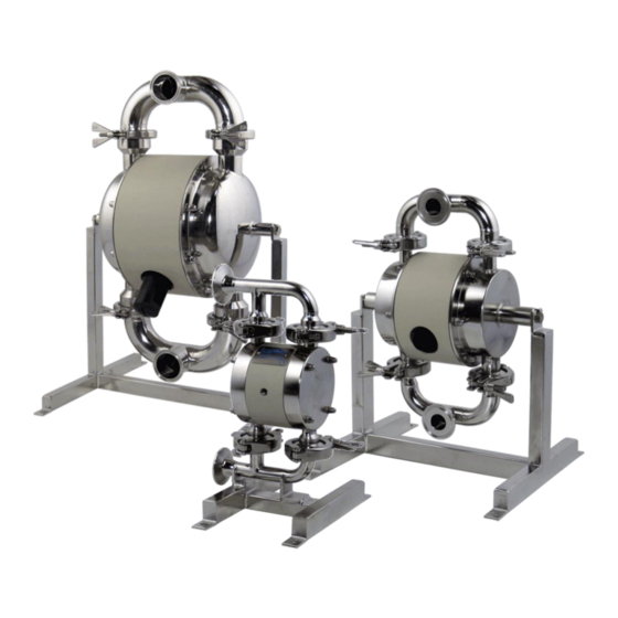
Sanitary series diaphragm pumps
Hide thumbs
Also See for T30:
- Instructions for installation, operation and maintenance (24 pages) ,
- Iom manual (50 pages)

Subscribe to Our Youtube Channel
Related Manuals for TapFlo T30


Summary of Contents for TapFlo T30
- Page 1 Sanitary Series Diaphragm Pumps edition 2016 rev 2 Read this instruction manual carefully, before you install and operate the pump Pump models: T/TX30 T/TX80 T/TX125 T/TX225 T/TX425 T825...
-
Page 2: Table Of Contents
CONTENTS GENERAL ............................6 0.1. Introduction..........................6 0.2. Warning symbols ........................6 0.3. Qualification and training of personnel ................... 6 INSTALLATION ..........................7 1.1. Operation principle ........................7 1.2. Receiving inspection ........................7 1.3. Storage ............................8 1.4. Foundation ..........................8 1.5. - Page 3 Routine inspection ........................15 3.3. Complete inspection ........................ 15 3.4. Location of faults ........................16 3.5. T30 – Disassembly of the pump ....................17 3.5.1. Before the disassembly procedure ................. 17 3.5.2. Disassembly procedure ....................17 3.6. T30 – Assembly of the pump ....................19 3.6.1.
- Page 4 CONTENTS 6.1. Capacity curves......................... 39 6.2. Capacity changes ........................39 6.3. Dimensions ..........................40 6.4. Technical data .......................... 41 6.5. Tightening torques ........................42 6.6. Permitted loads on manifolds ....................42 WARRANTY ..........................43 7.1. Warranty form .......................... 43 7.2. Returning parts ........................
- Page 5 EC Machinery directive 2006/42/EC, and is in conformity with the Pressure Equipment Directive (PED) 97/23/EC Category I. Manufactured by Tapflo Sp. z o. o., Poland for: Tapflo AB Filaregatan 4 S-442 34 Kungälv...
-
Page 6: General
0.1. Introduction The Tapflo Air Operated Diaphragm Pump range is a complete series of pumps for industrial applications. The pumps are designed to be safe, simple and easy to use and maintain. The construction is seal-less and without rotating parts. The pumps are suitable for a variety of duties in hygienic installations. -
Page 7: Installation
1.1. Operation principle The Tapflo diaphragm pump is driven by compressed air. The two diaphragms are connected by a diaphragm shaft and pushed back and forth by alternately pressurising the air chambers behind the diaphragms using an automatically cycling air valve system. -
Page 8: Storage
INTSTALLATION 1.3. Storage If the equipment is to be stored prior to installation, place it in a clean location. The pump should be stored in an ambient temperature of 15°C (59°F) to 25°C (77°F) and relative humidity below 65%. It should not be exposed to any heat source e.g. radiator, sun as this could result in a negative way on the tightness of the pump. -
Page 9: Health And Safety
1.6.3. Air pressure The maximum air pressure for Tapflo pumps is 8 bar. Higher air pressure than 8 bar can damage the pump and may cause injury to personnel in vicinity of the pump. If you intend to apply a higher air pressure than 8 bar, please consult us. -
Page 10: Noise Level
1.6.4. Noise level At tests, the noise level from a Tapflo pump has not exceeded 80 dB(A). Under some circumstances, for example if the pump is operating under high air pressure at low discharge head, the noise can be inconvenient or hazardous for personnel staying for long periods in the vicinity of the pump. -
Page 11: Example Of Installation
1.9.2. Self-priming The Tapflo pump is designed to pull a high vacuum. It is able to evacuate an empty suction pipe without any damage to the pump. The suction lift is up to 5 meters (16.4 ft.) from an empty suction pipe and up to 8 meters (26.2 ft.) from a wetted pipe. The suction capability depends on the pump size (see chapter 6. -
Page 12: Operation
For instance, a T80 pump should run continuous at maximum 40 l/min. As stated in chapter 1.7.1 Tapflo recommends to use an appropriate air treatment system in order to extend the pump’s lifetime. -
Page 13: Pump Stopping
2.4.1. CIP – Cleaning In Place The importance of easy cleaning is especially great in hygienic applications. Tapflo sanitary pumps are designed for CIP (cleaning in place). This allows the pump to be internally cleaned without disassembly. The pump can be cleaned by flushing through with a CIP fluid (usually a mild solution of sodium hydroxide and a sanitizing additive) or by injection of hot steam. -
Page 14: Drainage Of The Pump (T80 - T825)
2.4.1.1. Drainage of the pump (T80 – T825) After the CIP procedure, the pump usually has to be drained from the CIP fluid. The Tapflo sanitary series is supplied with a hygienic stand, enabling 360° rotation of the pump unit. -
Page 15: Maintenance
The characteristics of the liquid, temperature, materials used in the pump and running time decide how often a complete inspection is necessary. Nevertheless, Tapflo recommends to inspect the pump at least once a year. Parts from KIT AIR and KIT LIQ should be changed during inspection. See paragraph 4.7 for detailed KIT content. -
Page 16: Location Of Faults
MAINTENANCE 3.4. Location of faults PROBLEM POSSIBLE FAULT POSSIBLE SOLUTION The air pressure is to low Increase air pressure via a filter-regulator The air connection is blocked Check / clean air supply connection Muffler is blocked Check / clean / replace muffler The pump does not run Air valve is defective Clean / replace complete air valve... -
Page 17: T30 - Disassembly Of The Pump
MAINTENANCE 3.5. T30 – Disassembly of the pump The numbers put in brackets, refer to the part numbers in the spare part drawings and spare part lists in chapter 5 “SPARE PARTS”. 3.5.1. Before the disassembly procedure Be sure to drain all liquid from the pump. Cleanse or neutralize the pump thoroughly. - Page 18 MAINTENANCE Fig. 3.5.5 Unscrew the domed nuts [37] and remove the housing [11] from one side of the pump. Fig 3.5.6 Unscrew the diaphragm [15]. Fig 3.5.7 Turn the pump over, remove the domed nuts [37] and washers [38]. Take off the second housing [11]. Fig 3.5.8 Take out the pin screws [14] and unscrew the second diaphragm [15].
-
Page 19: T30 - Assembly Of The Pump
O-rings to provide smooth insertion of the air valve. It is recommended to use a pressing device for this operation. NOTE! When inserting the T30 size air valve, replace the shaft with a screw and a nut to make sure the air valve assembly remains properly fastened. -
Page 20: Test Run
MAINTENANCE Fig. 3.6.4 During assembly of the housings [11] make sure they are in the correct position – the inlet pipe has a valve ball stopper. Fig. 3.6.5 When fastening the domed nuts, remember to do it according to the tightening procedure and with the appropriate torque. -
Page 21: T80-T425 - Disassembly Of The Pump
Disassembly procedure Fig. 3.7.1 Unscrew and remove two tri-clamps [138] connecting the manifold [132] to the housings [11]. Fig. 3.7.2 Take off the manifold [132] and remove the valve balls [23] and sealing [18]. IOM manual Tapflo sanitary series pumps... - Page 22 MAINTENANCE Fig. 3.7.3 Unscrew and remove two tri-clamps [138] connecting the second manifold [131] to the housings [11]. Fig. 3.7.4 Remove the valve balls [23] and sealing [18]. Loosen the socket head cap screws [174] and take off the pump from the stand [17]. Fig.
- Page 23 MAINTENANCE Fig. 3.7.8 Take out the second diaphragm [15] along with the shaft [16]. a) Circlip mounted air valve – T/TX80, T125 Fig. 3.7.9 Using pliers remove both circlips [27] from the centre block [12]. Attention! While doing this, cover yourself with your other hand, as the circlip easily flips away Fig.
-
Page 24: T80-T425 - Assembly Of The Pump
MAINTENANCE c) Threaded air valve – T225 from 0803-… until 1105-… T425 from s/n 0801-… until 1105-… Fig. 3.7.13 Carefully unscrew both air valve end caps by means of a mounting tool. Fig. 3.7.14 Push out by hand the air valve shaft and piston. Fig. -
Page 25: Test Run
MAINTENANCE Fig. 3.8.1 When putting the air valve [61] into the centre block [12], apply some water or alcohol on the O-rings to provide smooth insertion of the air valve. It is recommended to use a pressing device for this operation. -
Page 26: Options
OPTIONS OPTIONS 4.1. Valve options In T225, T425 and T825 pump sizes flap valves or heavy duty valve cups (not available in T825) are available as an option instead of standard valves. 4.1.1. Flap valves It is a great option when the product we intend to pump has high viscosity, contains big solids or solids that can be damages by valve balls (e.g. -
Page 27: Ball Cup Valves
OPTIONS 4.1.2. Ball cup valves This option is a perfect solution when there is risk of damage to the valve seats from the product. If such situation is to occur there is no need to replace the whole manifolds or housings, just the valve cup what drastically reduces the spare parts cost. -
Page 28: Magnetic Ball Lifters
OPTIONS 4.3. Magnetic ball lifters New magnetic ball lifters have been implemented in pump sizes T125 – T425. They are implemented to enable pump emptying when no other draining option is available. Rotating the pump is no longer needed. The balls are lifted by simply attaching the magnets to the pumps manifold. Valve balls are available in AISI 420 magnetic stainless steel or PTFE wits steel core. -
Page 29: Spare Parts
SPARE PARTS SPARE PARTS 5.1. T30 – Spare parts drawing 5.2. T30 – Spare parts list Pos. Q-ty Description Material Housing AISI 316L Centre block PP, Conductive PP Manifold inlet and stand AISI 316L Manifold outlet AISI 316L 3-clamp AISI 304... -
Page 30: T80-T125 - Spare Parts Drawing
SPARE PARTS 5.3. T80-T125 – Spare parts drawing 5.4. T80-T125 – Spare parts list Pos. Q-ty Description Material Housing AISI 316L Centre block PP, PP Conductive Manifold inlet AISI 316L Manifold outlet AISI 316L 3-clamp AISI 304 Pin screw A4-80 EPDM, PTFE, NBR, PTFE/White EPDM, Diaphragm white EPDM... -
Page 31: T80 - T125 - Spare Parts Options
SPARE PARTS 5.5. T80 – T125 – Spare parts options Air valve reinforcement (T125 only) – std on TX125 Diaphragm stroke sensor Center block PP, PP Cond. Set of 2 reinforcement Centerblock for AISI 316L plates stroke sensor Screws 2711 A4-70 O-ring NBR, FKM, EPDM... -
Page 32: T225-T425 - Spare Parts Drawing
SPARE PARTS 5.6. T225-T425 – Spare parts drawing 5.7. T225-T425 – Spare parts list Pos. Q-ty Description Material KIT LIQ KIT AIR Housing AISI 316L Centre block PP, PP Conductive Manifold inlet AISI 316L Manifold outlet AISI 316L 4/8* 3-clamp AISI 304 Pin screw A4-80... -
Page 33: T225 - T425 - Spare Parts Options
SPARE PARTS 5.8. T225 – T425 – Spare parts options External control – built on solenoid valve Center block PP, PP Cond. Diaphragm stroke sensor Solenoid valve Centerblock for Threaded insert AISI 316L stroke sensor Screw A4-70 O-ring NBR, FKM, EPDM Inductive sensor CuZn Sensor cap... - Page 34 SPARE PARTS Flap valves Housing AISI316L Inlet manifold 131H AISI316L Outlet manifold 132H AISI316L Tri-clamp AISI304 Stand AISI304 Sealing PTFE, EPDM Flap valve seat 241H AISI316L Flap 242H AISI316L Flap valve complete AISI316L (241H+242H) Ball cup valves Housing AISI316L Inlet manifold 131C AISI316L Outlet manifold...
-
Page 35: T825 - Spare Parts Drawing
SPARE PARTS 5.9. T825 – Spare parts drawing 5.10. T825 – Spare parts list Pos. Description Material Q-ty Housing AISI 316L Centre block Manifold inlet AISI 316L Manifold outlet AISI 316L Pin screw A4-80 Manifold screw A4-70 Diaphragm EPDM, PTFE, NBR Diaphragm shaft AISI 304L Stand... -
Page 36: T825 - Spare Parts Options
SPARE PARTS Centre block seal Pin screw nut A4-70 Manifold screw nut A4-70 Pin screw washer A4-80 Manifold screw washer A4-70 O-ring (back up for 36) PET/NBR (standard); AISI 316/FKM, Brass/NBR, Air valve complete Brass/EPDM, AISI 316/FKM, PET/FKM 5.11. T825 – Spare parts options Air valve reinforcement Center block Set of 2 reinforcement... -
Page 37: Stocking Recommendation
5.13. How to order parts When ordering spare parts for Tapflo pumps, please let us know what is the model number and serial number from the pump centre body. Then just indicate the part numbers from the spare parts list and quantity of each item. -
Page 38: Pump Code
III. Max capacity [l/min] VI. Material of valve balls VII. Special executions S T T -7PV T = Tapflo diaphragm pump VI. Material of valve balls: = EPDM II. Basic options: N = NBR (nitrile rubber) B = Backup diaphragm pump... -
Page 39: Data
Recommended flow is half of the max flow, e.g. recommended flow for a T80 is 40 l/min. 6.2. Capacity changes Capacity changes at different suction lifts Capacity changes at different viscosities IOM manual Tapflo sanitary series pumps... -
Page 40: Dimensions
* = Dimensions for standard clamp connections only ** = Dimensions with flap valves and heavy duty valve cup version 1 = Clamp connections according to SMS3017 (T30 – T225) / ISO2037 (T425-T825) 2 = Threaded connections according to DIN 11851... -
Page 41: Technical Data
Brass (std.), stainless steel AISI 316L or PET Air valve with NBR (std.), EPDM or FKM O-rings Sealing (wetted) PTFE or EPDM Housing pin screws Stainless steel AISI 316 Diaphragm shaft Stainless steel AISI 316L (T30, T825) / 304L (T80 – T425) -
Page 42: Tightening Torques
DATA 6.5. Tightening torques The following tightening torques are recommended. PUMP SIZE MOUNTING TORQUE [Nm] T125 T225 T425 T825 30 (housing) / 35 (manifolds) 6.6. Permitted loads on manifolds We recommend not to exceed the following loads and forces reacting on the manifolds. T825 Load [N] Moment of force... -
Page 43: Warranty
%, of max size [mm]: Flow [l/min]: Duty [h/day]: No of starts per day: Discharge head [mWC]: Suction head / lift [m]: Air pressure [bar]: Quality of the air (filter, micron, lubrication): Other: Place for sketch of installation: IOM manual Tapflo sanitary series pumps... -
Page 44: Returning Parts
7.3. Warranty Tapflo warrants products under conditions as stated below for a period of not more than 5 years from installation and not more than 6 years from date of manufacturing. 1. The following terms and conditions apply to the sale of machinery, components and related services and products, of Tapflo (hereinafter “the products”). - Page 45 9. Tapflo will not be liable on any claim, whether in contact, tort, or otherwise, for any indirect, special, incidental, or consequential damages, caused to the customer or to third parties, including loss of profits, arising by any possible infringement of par.
- Page 46 Tech support: support@tapflo.com Tapflo products and services are available in 75 countries on 6 continents. Tapflo is represented worldwide by own Tapflo Group Companies and carefully selected distributors assuring highest Tapflo service quality for our customers’ convenience. AUSTRALIA | AUSTRIA | AZERBAIJAN | BAHRAIN | BELARUS | BELGIUM | BOSNIA & HERZEGOVINA | BRAZIL | BULGARIA |...
Need help?
Do you have a question about the T30 and is the answer not in the manual?
Questions and answers