Table of Contents
Advertisement
Quick Links
2014 rev. 1
Instructions for installation, start up, operation and maintenance.
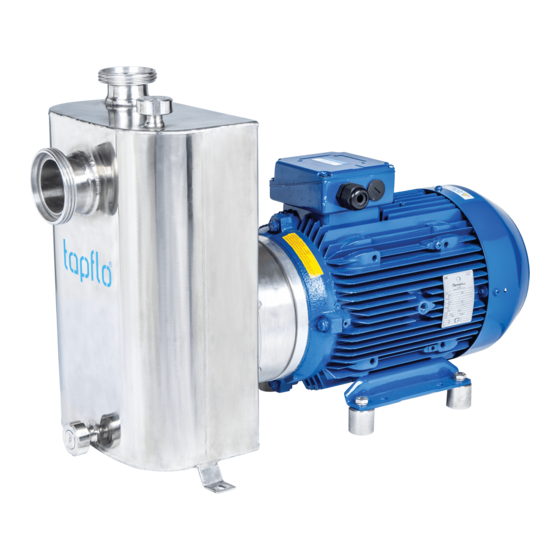
Self-priming CTS H pumps in electro polished AISI 316L stainless steel.
Self-priming CTS I pumps in glass blasted AISI 316L stainless steel.
Pump models:
CTS I
With 2900 rpm motor:
CTS I CC-22
CTS I CE-22
CTS I DD-40
CTS I DF-40
CTS I EF-55
CTS I EG-55
CTS I EF-75
CTS I EG-75
Read this instruction manual carefully,
before you install and operate the pump.
CTS H
With 2900 rpm motor:
CTS H CC-22
CTS H CE-22
CTS H DD-40
CTS H DF-40
CTS H EF-55
CTS H EG-55
CTS H EF-75
CTS H EG-75
Advertisement
Table of Contents

Related Manuals for TapFlo CTS I


Summary of Contents for TapFlo CTS I
- Page 1 2014 rev. 1 Instructions for installation, start up, operation and maintenance. Self-priming CTS H pumps in electro polished AISI 316L stainless steel. Self-priming CTS I pumps in glass blasted AISI 316L stainless steel. Pump models: CTS I CTS H With 2900 rpm motor:...
-
Page 2: Table Of Contents
CONTENTS GENERAL ........................... 5 0.1. Introduction ..........................5 0.2. Warning symbols ........................5 0.3. Qualification and training of personnel................... 5 INSTALLATION ..........................6 1.1. Operation principle ........................6 1.2. Receiving inspection ......................... 6 1.3. Storage ............................6 1.4. Foundation ..........................6 1.5. - Page 3 CONTENTS 3.3.1. Disassembly procedure ....................14 3.4. Assembly of the pump ......................15 Test run ........................... 17 3.4.1. SPARE PARTS ..........................18 4.1. Spare parts drawing ........................ 18 4.2. Spare parts list ......................... 18 4.3. Recommended spare parts ....................19 4.4.
- Page 4 CE CERTIFICATE IOM manual CTS self-priming pumps...
-
Page 5: General
AISI 316L. CTS H with excellent electro polished surfaces, FDA approved seals, high finish and mechanical strength, meet the demands from food and sanitary applications, CTS I with AISI 316L chemical resistance and mechanical strength is a reliable choice. The self-priming feature allows to use the pump in applications where standard CT pumps do not prove useful. -
Page 6: Installation
INSTALLATION INSTALLATION 1.1. Operation principle In order for the priming action to be achieved, the pump casing has to be filled with liquid to a level above the impeller (1). When the pump starts its operation, it is slowly sucking out the air from the suction line thus creating negative pressure and lifting the product. -
Page 7: Environment
1.7.1. Protection In the interest of health and safety it is essential to wear protective clothing and safety goggles when operating, and/or working in the vicinity of Tapflo pumps. IOM manual CTS self-priming pumps... -
Page 8: Electrical Safety
INSTALLATION 1.7.2. Electrical safety Do not carry out any maintenance or/and operation on the pump while it is running or before it has been disconnected from the power supply. Avoid any danger caused by electric power (for details see current regulations in force). Check that electrical specifications on the data plate are equivalent to the power supply to which it will be connected. -
Page 9: Example Of Installation
INSTALLATION 1.8. Example of installation 1) YES: Gate valve (may also be near pump in case of long piping) 2) With positive head: tilt of piping towards pump 3) YES: line strainer if particles are present 4) NO: air pockets – the circuit must be short and straight 5) YES: pipe fastening 6) Suction line as short and direct as possible 7) YES: attachment for gauge or safety pressure switch... -
Page 10: Electric Power
INSTALLATION 1.9.1. Electric power The electric power absorbed by the motor can be measured by means of a wattmeter. 1.9.2. Optional instruments The optional instruments can indicate if pump is working in an abnormal way. The abnormal conditions can be caused by: accidentally closed valves, lack of pumped liquid, overloads, etc. -
Page 11: Operation
OPERATION OPERATION 2.1. Start-up Check manually that the motor is free to turn, moving the motor cooling fan. Make sure that the piping is not clogged and is free from residues or foreign objects. Make sure that the liquid flows regularly into the pump. ... -
Page 12: Stopping The Pump
OPERATION 2.2. Stopping the pump It is advisable to close the discharge shut-off / regulation valve gradually and stop the motor immediately after. The reverse sequence is not recommendable, especially with larger pumps or longer delivery piping. That is to avoid any problems due to water hammering. -
Page 13: Maintenance
MAINTENANCE MAINTENANCE Maintenance work on electrical installations must be performed by qualified personnel and only when the power supply has been shutoff. Follow the local and national safety regulations. 3.1. Inspections Periodically check suction and discharge pressures. Inspect the motor according to the instructions from the motor manufacturer. ... -
Page 14: Disassembly Of The Pump
MAINTENANCE 3.3. Disassembly of the pump The disassembly should only be performed by qualified personnel. Each operation carried out on the machine must always be carried out once all the electrical contacts have been disconnected. The pump-motor unit must be placed in a position where it cannot be started unintentionally. -
Page 15: Assembly Of The Pump
MAINTENANCE Fig 3.3.7 If necessary, push out the static part [15B] of the mechanical seal. NOTE! Apply some alcohol or water before pushing out of the mechanical seal. Fig 3.3.8 Remove the deflector [17]. Fig 3.3.9 Remove the screws [121] and washers [122] holding the back cover [11] to the motor [10]. - Page 16 MAINTENANCE Fig. 3.4.2 Before assembly of the mechanical seal [15] wet the O-rings with alcohol. Fig. 3.4.3 After inserting the static part [15B] of the mechanical seal, fit the back casing [12] onto the back cover [11] and check the seal fitting dimension according to the table below.
-
Page 17: Test Run
MAINTENANCE Fig. 3.4.6 To screw in the casing pin screws [141S] use two nuts tightened against each other. 3.4.1. Test run We recommend you to conduct a test run of the pump before installing it in the system, so no liquid gets wasted if the pump leaks or perhaps does not start accordingly to wrong assembly of the pump. -
Page 18: Spare Parts
AISI 316L Ra<0.8 * Option Parts indicated as [H/N] have different execution for CTS I and CTS H pumps. When ordering spare parts please indicate if the part is for Industrial or Hygienic series e.g. 5-340N-11 or 5-340H-11. IOM manual CTS self-priming pumps... -
Page 19: Recommended Spare Parts
4.4. How to order parts When ordering spare parts for Tapflo pumps. please let us know what is the model number and serial number from the pump’s name plate. Then just indicate the part numbers from the spare parts list and quantity of each item. -
Page 20: Data
= Ex II 3G T135C motor - tropic = Motor with PTC thermistor 3. Connection options = 60 Hz motor Blank* = Thread BSP on CTS I Thread DIN 11851 on CTS H * = standard execution = BSPT thread (on CTS H) -
Page 21: Dimensions
DATA 5.2. Dimensions Dimensions in mm (where other is not indicated) Dimensions in inch (where other is not indicated) General dimensions only, ask us for detailed drawings. Changes reserved without notice. MODEL CC-22 CE-22 DD-40 DF-40 EF-55 EG-55 EF-75 EG-75 Motor power IEC motor... -
Page 22: Materials, Data And Limits
DATA Connection dimensions BSPT Connection dimensions DIN 11851 (male thread) (male thread) Model Model 1 ½” 1 ½” CTSI C CTSH C DN40 DN40 2 ½” 2” CTSI D CTSH D DN65 DN50 2 ½” 2” CTSI E CTSH E DN65 DN50 5.3. -
Page 23: Performance Curves
DATA 5.5. Performance curves The performance curves are based on water at 20°C. CTS CC-22 CTS CE-22 CTS DF-40 CTS EG-75 ³ Q [ m /h ] CTS CC-22 CTS CE-22 CTS DF-40 CTS EG-75 ³ Q [ m /h ] IOM manual CTS self-priming pumps... - Page 24 DATA CTS CC-22 CTS CE-22 CTS DF-40 CTS EG-75 ³ Q [ m /h ] CTS CC-22, DN40, φ125 CTS CE-22, DN40, φ135 CTS DF-40, DN65, φ155 CTS EG-75, DN65, φ180 Suction head [ m ] IOM manual CTS self-priming pumps...
-
Page 25: Warranty
6.2. Warranty Tapflo warrants products under conditions as stated below for a period of not more than 12 months from installation and not more than 24 months from date of manufacturing. 1. The following terms and conditions apply to the sale of machinery. components and related services and products. - Page 26 9. Tapflo will not be liable on any claim. whether in contact. tort. or otherwise. for any indirect. special. incidental. or consequential damages. caused to the customer or to third parties.
-
Page 27: Warranty Form
WARRANTY 6.3. Warranty form Company: Telephone: Fax: Address: Country: Contact Name: E-mail: Delivery Date: Date of pump installation: Pump type: Serial No (see name plate): Description of the fault: The installation: Liquid: Temperature [°C]: Viscosity [cPs]: Spec grav. [kg/m pH-value: Content of particles: %, of max size [mm]: Flow [l/min]:... - Page 28 Baltic States France Poland Ukraine Tapflo Latvia Tapflo France Tapflo Sp. z o.o. TOB Tapflo Tel: +371 67472205 Tel: +33 1 34 78 82 40 Tel: +48 58 5301181 Tel: +380 44 222 68 44 riga@tapflo.lv info@tapflo.fr gda@tapflo.pl sales@tapflo.com.ua...
Need help?
Do you have a question about the CTS I and is the answer not in the manual?
Questions and answers