
Related Manuals for TapFlo Steinle Filter Press Pump Series


Summary of Contents for TapFlo Steinle Filter Press Pump Series
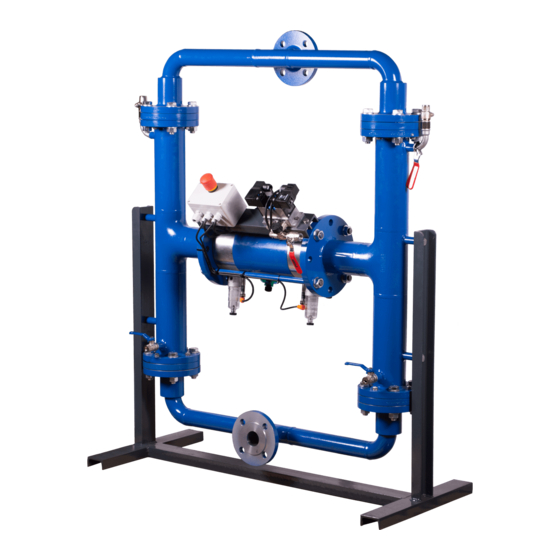
- Page 1 Steinle Filter Press Pump Series edition 2020 rev 1 Original Instruction Read this instruction manual carefully, before you install and operate the pump Pump models: FP/FH 25 FP/FH 40 FP/FH 50 FP/FH 80...
-
Page 2: Table Of Contents
24V DC power supply with diaphragm control unit ............. 15 1.11.3.4. 230V AC power supply with diaphragm control unit ........... 16 1.12. Diaphragm control unit for FP/FH Pumps Series .............. 16 1.12.1. Installation of the sensors ....................16 Steinle Filter Press Pump Series... - Page 3 3.8.3.2. Discharge Side ......................34 3.9. Filling of Hydraulic Liquid ....................34 3.9.1. Pump is flooded from the suction side ................34 3.9.2. Pump is not flooded ......................35 3.9.3. Changing stroke sensors ....................35 Steinle Filter Press Pump Series...
- Page 4 Dimensions ..........................57 5.4. Technical data .......................... 59 5.5. Tightening torques ........................60 5.6. Permitted manifold loads ......................61 WARRANTY ..........................62 6.1. Warranty form .......................... 62 6.2. Returning parts ........................63 6.3. Warranty ........................... 63 Steinle Filter Press Pump Series...
- Page 5 Directive 2006/42/EC of European Parliament and of the Council of 17 May 2006 on • machinery, amending Directive 95/16/EC; Mr Michał Śmigiel is authorized to compile the technical file. Tapflo Sp. z o.o. ul. Czatkowska 4b 83-110 Tczew Signed for and on behalf of Tapflo AB Håkan Ekstrand...
-
Page 6: General
The personnel in charge of installation, operation and maintenance of the pumps we produce must be qualified to carry out the operations described in this manual. Tapflo shall not be held responsible for the training level of personnel and for the fact that they are not fully aware of the contents of this manual. -
Page 7: Installation
While the hose is compressed, the slurry inside is displaced and flows out. Ball valves on the top and bottom of the hose ensure that the flow is in one direction only. a: open b: compressed The two extreme deformation conditions of the hose Steinle Filter Press Pump Series... -
Page 8: Receiving Inspection
Always use at least two slings and make sure they are secured in such a way to prevent the pump from slipping and that the pump unit is hanging straight. Never lift the pump with only one sling. Incorrect lifting can cause serious injury and/or damage to the pump. Steinle Filter Press Pump Series... -
Page 9: Storage
Do not remove the protective covers from the suction, discharge and air connections which have been fastened to keep pump internals free of debris. Clean the pump thoroughly before installation. Steinle Filter Press Pump Series... -
Page 10: Foundation
1.7.1. Protection In the interest of health and safety it is essential to wear protective clothing and safety goggles when operating, and/or working in the vicinity of Tapflo pumps. Steinle Filter Press Pump Series... -
Page 11: Air Pressure
Please contact Tapflo for tightening intervals recommendation. Below 0°C (32°F) plastic materials become more fragile what can cause accelerated wear of parts made of these materials. -
Page 12: Air Quality Classes
3) Needle valve to adjust the air flow (especially when operating the pump in the lower range of performance); 4) Filter. These components are included in Tapflo’s Air treatment system which can be ordered from Air quality classes 1.8.2. ISO 8573-1:2010 Compressed Air Contaminants and Purity Classes... -
Page 13: Installation Example
The pump needs a power supply for the operation of the solenoid valve. Please keep care, that the installation is done properly according to the national standards. Tight the cable fittings to avoid the ingress of water. All internal cable wiring is done. Steinle Filter Press Pump Series... -
Page 14: Dc (Standard)
The power supply is connected to the clamps inside the control box, marked with L, N, and PE (ground connection). Keep care, that the ground connection is installed properly. 1.11.3. Connection diagram 1.11.3.1. 24V DC power supply - Standard Steinle Filter Press Pump Series... -
Page 15: 230V Ac Power Supply
INSTALLATION 1.11.3.2. 230V AC power supply 1.11.3.3. 24V DC power supply with diaphragm control unit Steinle Filter Press Pump Series... -
Page 16: 230V Ac Power Supply With Diaphragm Control Unit
After taking the sensor out of the slurry, the relay must go back to neutral position again. If not, clean the surface of the sensor. This can be done while power is switched on. Steinle Filter Press Pump Series... -
Page 17: Control Unit Signals
Off as soon as current flows from 16/18 to 17/19 - (diaphragm break) Signals (terminal contacts short circuited): No Power: 21 - 22 No Alarm, LED green: 20 - 21 Alarm, LED green off: 21 - 22 Steinle Filter Press Pump Series... -
Page 18: Operation
Running at full frequency (maximum air pressure/flow) continuously will cause premature wear of the components. As stated in chapter 1.8.1 Tapflo recommends using an appropriate air treatment system in order to extend the pump’s lifetime. If the air humidity is high, use of a water separator or air dryer is recommended. -
Page 19: Pump Stopping
In case of a leakage of an unknown fluid, respiratory protection should be worn and contact with the fluid avoided. During firefighting, keep in mind that hydraulic part of pump is filled with oil and control unit is connected to electricity. In addition, the currently Steinle Filter Press Pump Series... - Page 20 OPERATION handled fluid and the corresponding safety data sheet must be taken into account. In the event of personal injury, the appropriate emergency number or 112 must be chosen. Steinle Filter Press Pump Series...
-
Page 21: Maintenance
3.5 "Location of faults" and 3.6, 3.7 "Dismantling of the pump". You are of course warmly welcome to consult us for further help. Parts that are subject to wear should be kept in stock, see our recommendations in chapter 4.7 “Stocking recommendation”. Steinle Filter Press Pump Series... -
Page 22: Location Of Faults
Wrong selection of material breakdown selection Pump has no flow Pressure from discharge pipe press To drain air from the pump use back flow after service the balls into the seats pipe(open the back flow pipe) Steinle Filter Press Pump Series... -
Page 23: Fp/Fh 25 - Disassembly Of The Pump
Ventilation screw [62] for the hydraulic liquid. Fig. 3.6.3a Fig. 3.6.3b Disconnect two air hoses [33] connecting the Unscrew and remove two hex screws [61] connecting outlet manifold [3] to the housings [1]. the control unit [35] to the housings [1]. Steinle Filter Press Pump Series... - Page 24 [1]. Fig. 3.6.5b Fig. 3.6.5c Remove discharge manifold [3] from the housings Remove Ball Retainers [11], valve balls [20], Valve [1]. Seats [19], O-rings Valve seat [16] and O-rings Flange [24] from the housings [1]. Steinle Filter Press Pump Series...
- Page 25 Bush discharge [12] with O-ring Discharge [52]. screws, Medium Flange [15], Hose Bushes [12] - discharge, [9] - suction and O-rings [52 and 72]. Fig 3.6.9 Fig 3.6.10 Remove Balance Tubes [10]. Remove Diaphragm O-rings [23] and Tubular Diaphragm. Steinle Filter Press Pump Series...
- Page 26 Disassembly Leading flange [40], Hydraulic Seal Oil Disassembly Hydraulic Seal Air side [22], Slide Ring side [25] and O-ring [51] from Hydraulic piston [7]. Hydraulic Piston [28], O-Ring Pneumatic Cylinder [26], P-Flange [14] and O-Ring P-Flange [51] Steinle Filter Press Pump Series...
-
Page 27: Test Run
We recommend you conduct a test run of the pump before installing it in the system, so no liquid gets wasted if the pump leaks or perhaps does not start accordingly to wrong assembly of the pump. After a few weeks of operation retighten the nuts with appropriate torque. Steinle Filter Press Pump Series... -
Page 28: Fp/Fh 40-80 - Disassembly Of The Pump
Fig. 3.7.3b Disconnect two air hoses [33] connecting the outlet Unscrew and remove two hex screws, nuts and manifold [3] to the housings [1]. washers [65] connecting the control unit [35] to the housings [1]. Steinle Filter Press Pump Series... - Page 29 Remove discharge manifold [3] from the housings Remove O-rings valve seat [16], Valve seats [19], [1]. valve balls [20], Ball Retainer [71] and O-rings flange [24] by repeating steps 3.6.5 a to c for suction side. Steinle Filter Press Pump Series...
- Page 30 [12] with O-ring Discharge [52]. screws, Medium Flanges [15], Hose Bushes [12] - discharge, [9] - suction and O-rings [52 and 72]. Fig. 3.7.9 Fig. 3.7.10 Remove Balance Tubes [10]. Remove Diaphragm O-rings [23] and Tubular Diaphragm [18]. Steinle Filter Press Pump Series...
- Page 31 Disassembly Piston [6] from cylinder [4]. [46-FP40 or 47-FP50/80] Nut + Sealing Washer; [17] Piston Cover; [29] O-Ring Piston Cover; [7] Piston Hydraulic; [41] O-Ring Piston Hydraulic; [50] O-Ring Muffling Discharge Stroke; [27] Slide Ring Pneumatic Piston. Steinle Filter Press Pump Series...
-
Page 32: Fp/Fh - Assembly Of The Pump
The assembly procedure is done in the reverse order to the disassembly. Nevertheless, there are a few things that you have to remember in order to assemble the pump correctly. For details see chapter 3.8 “Changing the parts”. Steinle Filter Press Pump Series... -
Page 33: Changing The Parts
Assemble (2, 24, 16,19, 20, and 11) and put on the housing, make sure that the balance tube is put over the guiding on ball stop (11). Tighten the Screw with Nut (38) and then the nuts on the medium flange. Steinle Filter Press Pump Series... -
Page 34: Discharge Side
Attention! Piston moves only, when the valve on the discharge is opened. Now the right side can be filled like described above. Put all cables back and pump is ready. Steinle Filter Press Pump Series... -
Page 35: Pump Is Not Flooded
We recommend you conduct a test run of the pump before installing it in the system, so no liquid gets wasted if the pump leaks or perhaps does not start accordingly to wrong assembly of the pump. After a few weeks of operation retighten the nuts with appropriate torque. Steinle Filter Press Pump Series... -
Page 36: Spare Parts
SPARE PARTS SPARE PARTS 4.1. FP-FH 25 – Spare parts drawings Suction side 4.1.1. The quantities given apply to entire pump. Steinle Filter Press Pump Series... - Page 37 SPARE PARTS Discharge side 4.1.2. The quantities given apply to entire pump. Steinle Filter Press Pump Series...
- Page 38 SPARE PARTS Cylinder section 4.1.3. The quantities given apply to entire pump. 13.1 Steinle Filter Press Pump Series...
-
Page 39: Fp-Fh 25 - Spare Parts List
O-Ring Valve Seat 11-4001620 Piston Cover Aluminium 11-40C1710 Superflex 11-40C1830 Tubular Diaphragm PUR blue 11-40C1836 Steel 11-4001901 Valve Seat PE1000 11-4001932 stainless steel 11-4001906 6-200-23-3 6-200-23-4 Valve Ball PTFE-TFM 6-200-23-1-5 PE1000 6-200-23-22 CR Steel core 11-4002024 Steinle Filter Press Pump Series... - Page 40 Bolt hose bush (included in pos. 12) 11-4007031 stainless steel 11-4007006 O-Ring Hose Bush suction 11-40E7220 Barrel Nipple AISI 316L 11-40E7306 Ball Valve Brass/Nickel 11-40E8003 Elbow 90° Zinc coated steel 11-4008104 Needle Valve Air Inlet + elbow Brass/Nickel 11-40E8591 Steinle Filter Press Pump Series...
-
Page 41: Fp-Fh 40 - Spare Parts Drawing
SPARE PARTS 4.3. FP-FH 40 – Spare parts drawing Suction side 4.3.1. The quantities given apply to entire pump. Steinle Filter Press Pump Series... - Page 42 SPARE PARTS Discharge side 4.3.2. The quantities given apply to entire pump. Steinle Filter Press Pump Series...
- Page 43 SPARE PARTS Cylinder section 4.3.3. The quantities given apply to entire pump. Steinle Filter Press Pump Series...
-
Page 44: Fp-Fh 40 - Spare Parts List
Manifold connection pipe 11-40C0231-C O-ring PP flange with connection pipe 11-40E6821 Steel Cylinder Pneumatik FP 11-40C0401 Steel Cylinder Pneumatik FH 11-40HC0401 Valve Frame AISI 304L 11-40E0506 Piston Pneumatic FP Steel 11-40C0601 Piston Pneumatic FH Steel 11-4HC0601 Steinle Filter Press Pump Series... - Page 45 Slide Ring Pneumatic Piston FH PTFE compound 11-4HC2734 Slide Ring Hydraulic Piston PTFE compound 11-40C2834 O-Ring Piston Cover 11-40C2920 Inductive sensor 11-4003090 Solenoid Valve Aluminium 11-40E3190 Quick exhaust valve Brass/Nickel 11-40E3290 Air Hose 11-40E3337 Muffler Aluminium 11-40E3410 Steinle Filter Press Pump Series...
- Page 46 Bolt hose bush (included in pos. 12) 11-4007031 stainless steel 11-4007006 O-Ring Hose Bush suction 11-40E7220 Barrel Nipple AISI 316L 11-40E7306 Ball Valve Brass/Nickel 11-40E8003 Elbow 90° Zinc coated steel 11-4008104 Needle Valve Air Inlet Brass/Nickel 11-40E8591 Steinle Filter Press Pump Series...
-
Page 47: Fp-Fh 50/80 - Spare Parts Drawing
SPARE PARTS 4.5. FP-FH 50/80 – Spare parts drawing Suction side 4.5.1. The quantities given apply to entire pump. Steinle Filter Press Pump Series... - Page 48 SPARE PARTS Discharge side 4.5.2. The quantities given apply to entire pump. Steinle Filter Press Pump Series...
- Page 49 SPARE PARTS Cylinder section 4.5.3. The quantities given apply to entire pump. Steinle Filter Press Pump Series...
-
Page 50: Fp-Fh 50/80 - Spare Parts List
11-5001231 stainless steel 11-5001206 steel 11-5001201-U Hose Bush discharge for PUR diaphragm 11-5001231-U stainless steel 11-5001206-U P-Flange FP Aluminum 11-50E1410 P-Flange FH Aluminum 11-5HE1410 steel 11-5001501 Medium Flange stainless steel 11-5001506 O-Ring Valve Seat 11-5001620 Steinle Filter Press Pump Series... - Page 51 Screw with Washer 8.8 ZN 11-2506104 Ventilation Screw 8.8 ZN 11-50E6206 Muffler Bronze Bronce 11-50C6311 Screw with nut and washers for control box A4-70 11-40E6506 assembly steel 11-5007001 Bolt hose bush (included in pos. 12) 11-5007031 Steinle Filter Press Pump Series...
- Page 52 SPARE PARTS stainless steel 11-5007006 O-Ring Hose Bush suction 11-50E7220 Barrel Nipple 11-50E7306 Adapter Steel 11-50E7401 Ball Valve Brass/Nickel 11-40E8003 Elbow 90° Zinc coated steel 11-4008104 Needle Valve Air Inlet Brass/Nickel 11-5008511 Steinle Filter Press Pump Series...
-
Page 53: Stocking Recommendation
Sealing set complete 1 - For pump size 40 2 - Only PP pumps 3 - 3 liters for FP/FH 25; 6 liters for FP/FH 40 4 - Designated for proper type of pump (FP or FH). Steinle Filter Press Pump Series... -
Page 54: How To Order Parts
Please note that pump codification has been updated. If you are going to place an order for spare parts for pump manufactured before 07 2019 please review actual spare parts drawings and list. Steinle Filter Press Pump Series... -
Page 55: Pump Code
E = Last standard manufactured at Steinle (std. on Fx50, Fx80 and all PP pumps) F = Current standard - manufactured at A = Flange acc. to ANSI 16.5B Class 150 Tapflo J = Flange acc. to JIS Steinle Filter Press Pump Series... -
Page 56: Data
See below how the capacity will change at different viscosities and suction lifts. Example FP 40: With an existing pressure of 5 bar in compressed air supply, the pump delivers 3,5 m³/h at approximately 4 bar. Air consumption will be 0,65 m³/min in this case. Steinle Filter Press Pump Series... -
Page 57: Capacity Changes
806 / 31.73 806 / 31.73 860 / 33.86 860 / 33.86 249 / 9.80 249 / 9.80 273 / 10.75 273 / 10.75 133 / 5.24 133 / 5.24 196 / 7.72 196 / 7.72 Steinle Filter Press Pump Series... - Page 58 DATA Steinle Filter Press Pump Series...
-
Page 59: Technical Data
Screws A4-70 Valve seat parts, hose bush Steel, PP, stainless steel Exhaust silencer Aluminium Pneumatic cylinder St 52 Piston pneumatic parts Hydraulic piston S355 / St52-3 Balance tube Mount AISI 304L Hydraulic liquid Biological degradable Steinle Filter Press Pump Series... -
Page 60: Tightening Torques
What is more for proper operation and safety the torque values should be checked frequently as part of preventive maintenance (please contact Tapflo for interval proposals). FP25/40 CS/SS... -
Page 61: Permitted Manifold Loads
(inlet/outlet) [Nm] FP40 PP Load [N] Moment of force Direction (inlet/outlet) (inlet/outlet) [Nm] FP50 CS/SS Load [N] Moment of force Direction (inlet/outlet) (inlet/outlet) [Nm] FP50 PP Load [N] Moment of force Direction (inlet/outlet) (inlet/outlet) [Nm] Steinle Filter Press Pump Series... -
Page 62: Warranty
%, of max size [mm]: Flow [l/min]: Duty [h/day]: No of starts per day: Discharge head [mWC]: Suction head / lift [m]: Air pressure [bar]: Quality of the air (filter, micron, lubrication): Other: Place for sketch of installation: Steinle Filter Press Pump Series... -
Page 63: Returning Parts
6.3. Warranty Tapflo warrants products under conditions as stated below for a period of not more than 5 years from installation and not more than 6 years from date of manufacturing. 1. The following terms and conditions apply to the sale of machinery, components and related services and products, of Tapflo (hereinafter “the products”). - Page 64 9. Tapflo will not be liable on any claim, whether in contact, tort, or otherwise, for any indirect, special, incidental, or consequential damages, caused to the customer or to third parties, including loss of profits, arising by any possible infringement of par.
Need help?
Do you have a question about the Steinle Filter Press Pump Series and is the answer not in the manual?
Questions and answers