Table of Contents
Advertisement
Quick Links
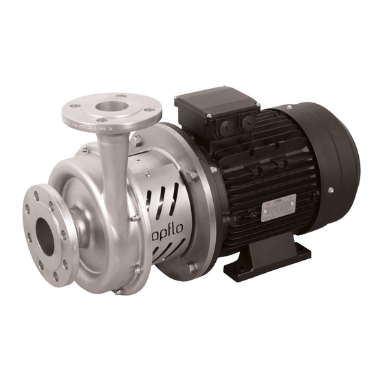
CTX High Performance
Read this instruction manual carefully,
before you install and operate the pump
CTX I
CTX I 40-165
CTX I 50-145
CTX I 50-200
CTX I 65-175
CTX I 65-230
CTX I 65-240
CTX I 80-205
CTX I 80-212
CTX I 80-260
CTX I 100-230
Centrifugal Pumps
CTX H
CTX H 40-165
CTX H 50-145
CTX H 50-200
CTX H 65-175
CTX H 65-230
CTX H 65-240
CTX H 80-205
CTX H 80-212
CTX H 80-260
CTX H 100-230
Original instruction
2020 | 1
.
Advertisement
Table of Contents

Related Manuals for TapFlo CTX I


Summary of Contents for TapFlo CTX I
- Page 1 Original instruction 2020 | 1 Read this instruction manual carefully, before you install and operate the pump CTX I CTX H CTX I 40-165 CTX H 40-165 CTX I 50-145 CTX H 50-145 CTX I 50-200 CTX H 50-200 CTX I 65-175...
-
Page 2: Table Of Contents
CONTENTS EC DECLARATION OF CONFORMITY 01/EC/CTX/2020 ................4 GENERAL ............................. 5 0.1. Introduction..........................5 0.2. Warning symbols ........................5 0.3. Qualification and training of personnel ................... 5 INSTALLATION ........................... 6 1.1. Operation principle ........................6 1.2. Receiving inspection ........................6 1.3. - Page 3 CONTENTS 2.6. Waste of electrical and electronic equipment (WEEE) directive .......... 15 2.7. Actions in emergency ......................15 MAINTENANCE ..........................16 3.1. Inspections ..........................16 3.2. Location of faults ........................16 3.3. Disassembly of the pump ......................17 3.3.1. Disassembly procedure ....................17 3.4.
-
Page 4: Ec Declaration Of Conformity 01/Ec/Ctx/2020
Member States relating to electrical equipment designed for use within certain voltage limits; Mr Michał Śmigiel is authorized to compile the technical file. Tapflo Sp. z o.o. ul. Czatkowska 4b 83-110 Tczew Signed for and on behalf of Tapflo AB: Håkan Ekstrand Managing director Tapflo AB, 02.02.2020 www.tapflo.com... -
Page 5: General
AISI 304/316L. The pump range meets the demands from a variety of today’s industries. The industrial series CTX I is designed with sand blasted pump casing. A variety of connection types, mechanical seal options and other executions are available to satisfy most type of industrial duties. -
Page 6: Installation
INSTALLATION INSTALLATION 1.1. Operation principle In order to operate the pump, the casing has to be filled with liquid before start-up. The liquid enters the pump casing axially to the shaft. The rotating impeller generates a centrifugal force accelerating the liquid through the pump casing and into the discharge piping. -
Page 7: Storage
INSTALLATION 1.4. Storage If the equipment is to be stored prior to installation, place it in a clean location. Do not remove the protective covers from the suction and discharge which have been fastened to keep pump internals free of debris. Clean the pump thoroughly before installation. When in storage, turn the shaft by hand at least once per month. -
Page 8: Connection Of Suction Pipe
1.8.1. Protection In the interest of health and safety it is essential to wear protective clothing and safety goggles when operating, and/or working in the vicinity of Tapflo pumps. IOM manual CTX centrifugal pumps... -
Page 9: Electrical Safety
INSTALLATION 1.8.2. Electrical safety Do not carry out any maintenance or/and operation on the pump while it is running or before it has been disconnected from the power supply. Avoid any danger caused by electric power (for details see current regulations in force). Check that electrical specifications on the data plate are equivalent to the power supply to which it will be connected. -
Page 10: Example Of Installation
INSTALLATION 1.9. Example of installation YES: Gate valve (may also be near pump in case of long piping) With positive head: tilt of piping towards pump YES: line strainer if particles are present NO: air pockets – the circuit must be short and straight YES: pipe fastening Suction line as short and direct as possible YES: attachment for gauge or safety pressure switch... -
Page 11: Electric Power
INSTALLATION The pressure intakes must be made of straight pieces of piping at a distance of minimum five diameters from the pump inlets. The pressure gauge on discharge must always be fitted between the pump and the shut-off / regulation valve. The output can be read on the pressure gauge, transformed into meters and then compared with the typical curves. -
Page 12: Motor Standard
INSTALLATION 1.12. Motor standard As a standard Tapflo CTX pump are equipped with motors of the following parameters: ➢ International Mounting Arrangement – B35 ➢ Number of poles / Rotation speed [rpm] – 2 ➢ Non ATEX ➢ Protection grade – IP55 ➢... -
Page 13: Operation
OPERATION OPERATION 2.1. Start-up ➢ Check manually that the motor is free to turn, moving the motor cooling fan. ➢ Make sure that the piping is not clogged and is free from residues or foreign objects. Make sure that the liquid flows regularly into the pump. ➢... -
Page 14: Stopping The Pump
OPERATION 2.2. Stopping the pump It is advisable to close the discharge shut-off / regulation valve gradually and stop the motor immediately after. The reverse sequence is not recommendable, especially with larger pumps or longer delivery piping. That is to avoid any problems due to water hammering. If a suction shutoff valve has been installed, it is advisable to close it completely after pump is fully stopped. -
Page 15: Residual Risks
OPERATION 2.4. Residual risks Even with proper application and observance of all points listed in this operating manual, there is still an estimable and unexpected residual risk when using the pumps. It may leak, fail due to wear, application-related causes or system-related circumstances. 2.5. -
Page 16: Maintenance
MAINTENANCE MAINTENANCE Maintenance work on electrical installations must be performed by qualified personnel and only when the power supply has been shut off. Follow the local and national safety regulations. 3.1. Inspections ➢ Periodically check suction and discharge pressures. ➢ Inspect the motor according to the instructions from the motor manufacturer. ➢... -
Page 17: Disassembly Of The Pump
MAINTENANCE 3.3. Disassembly of the pump The disassembly should be performed only by qualified personnel. Each operation to be fulfilled with the machine must always be carried out once all the electrical contacts have been disconnected. The pump-motor unit must be placed in a position where it cannot be started unintentionally. - Page 18 MAINTENANCE Fig 3.3.5 Fig 3.3.6 Remove the casing O-ring [18]. Use a bar to fix the shaft in place and unscrew the NOTE! After every disassembly the O-ring [18] impeller nut [191] and remove the O-ring [192]. should be replaced by a new one. NOTE! Apply grease on the thread before re-assembly.
- Page 19 MAINTENANCE Fig 3.3.11 Fig 3.3.12 Remove the circlip by means of pliers and push Remove the bolts [121], washers [122] and nuts out the static part of the mechanical seal. [123] fastening the lantern [11] to the electric motor. Fig 3.3.13 Fig 3.3.14 Remove the lantern [11].
-
Page 20: Assembly Of The Pump
MAINTENANCE Fig 3.3.17 Remove the shaft [16]. The pump is now completely disassembled. Check all components, especially the mechanical seal, for wear or damage and replace if necessary. The casing O-ring should be replaced after every pump disassembly! 3.4. Assembly of the pump The assembly procedure is done in the reverse order to the disassembly. - Page 21 MAINTENANCE Fig. 3.4.3 Fig. 3.4.4 Precisely clean and degrease with alcohol the Before assembly lubricate the mechanical seal internal rim of the back casing [12] as well as the O-rings to provide more accurate assembly as well shaft [16] surface. Check if the rim surface is as prevent the O-ring from curling.
- Page 22 MAINTENANCE Fig. 3.4.7 Fig. 3.4.8 Install back casing, impeller, insert spacer ring Proper gap between the impeller and the back tool. Install casing, screw every second casing casing has to be set. Push the impeller to the mounting screws nuts and washers. housing through the shaft, then tighten the shaft screws.
-
Page 23: Test Run
MAINTENANCE After installation of the impeller, proper gap “A” between the impeller and the back casing has to be set. Loosen the shaft screws [161] and using a spacer ring tool(A) feeler (gap) gauge (B) set the appropriate gap. Pump type A [mm] B [mm] CTX 40-165... -
Page 24: Options
OPTIONS OPTIONS 4.1. Motor shroud – M/N An optional motor shroud is available. It is made of stainless steel and provides easy cleaning and splash protection for the electrical motor. As a standard, the pump with the shroud is equipped with feet (M) or bracket (N). -
Page 25: Spare Parts
SPARE PARTS SPARE PARTS 5.1. Spare parts drawing IOM manual CTX centrifugal pumps... -
Page 26: Spare Parts List
** CTX 100-230, 80-260, 80-212, 80-205, 65-240, 65-230 / 65-175, 50-200, 50-145, 40-165 *** Parts indicated as [H/N] have different execution for CTX I and CTX H pumps. When ordering spare parts please indicate if the part is for Industrial or Hygienic series e.g. 14-145N-11 or 14-145H-11. -
Page 27: Data
= Double mechanical seal – back-to-back = Industrial = Hygienic 3. Connection options Blank* = EN 1092-1 flange on CTX I III. Pump size (inlet DN – max impeller diameter [mm]): Thread DIN 11851 on CTX H 40-165 = ANSI flange (CTX I only) -
Page 28: Dimensions
DATA 6.2. Dimensions Dimensions in mm (where other is not indicated) General dimensions only, ask us for detailed drawings. Changes reserved without notice. øD øD1 øE øE1 40-165-15 40-165-22 40-165-30 100L 58.5 70.5 37.2 39.3 40-165-40 112M 40-165-55 132S 40-165-75 132S 50-145-15 50-145-22... - Page 29 DATA 65-240-450 225M 80-205-55 132S 80-205-75 132S 80-205-110 160M 80-205-150 160M 14.5 14.5 80-205-185 18.5 160L 54.5 82.5 80-205-220 180M 80-205-300 200L 80-205-370 200L 305 18.5 18.5 80-205-450 225M 754.5 759.5 65-230-55 132S 65-230-75 132S 65-230-110 160M 65-230-150 160M 14.5 14.5 65-230-185 18.5...
- Page 30 DATA Dimensions in mm (where other is not indicated) General dimensions only, ask us for detailed drawings. Changes reserved without notice. øD øD1 øE øE1 øJ øJ1 øL 40-165-15 186/ 583 592.6 283 230 370 261.5 190 146** 40-165-22 40-165-30 3.0 100L 280.5 198 58.5 70.5...
- Page 31 DATA 80-205-55 5.5 132S 222.5 12 759.5 764.5 402.5 226 320 465 360.5 225 80-205-75 7.5 132S 80-205-110 11 160M 80-205-150 15 160M 247.5 944.5 949.5 517.5 280 406 589 407.5 260 80-205-185 18.5 160L 96 101 50 54.5 81 82.5 80-205-220 22 180M 250.5 984.5 989.5 552.5 316...
-
Page 32: Materials, Data And Limits
76.1 4” ” 6.3. Materials, data and limits CTX H … CTX I … Casing Stainless steel AISI 316L electro polished Ra<0.8 Stainless steel AISI 316L sand blasted Ra<3.2 Open impeller Stainless steel AISI 316L electro polished Ra<0.8 Stainless steel AISI 316L electro polished Ra<3.2... -
Page 33: Mounting Torques And Dimensions Of Screws/Nuts
DATA 6.4. Mounting torques and dimensions of screws/nuts CTX 65-230; CTX 65-240; Screw / CTX 40-165 Description CTX 80-205; CTX 80-212; nut type CTX 50-145 50-200 65-175 CTX 80-260; CTX 100-230 Pos. 141. DIN 933 bolt Mounting torque [Nm] Tool size “S” [mm] Thread Pos. -
Page 34: Performance Curves
DATA 6.5. Performance curves he performance curves are based on water at 20° . Contact us for detailed curves Speed 2900 rpm IOM manual CTX centrifugal pumps... -
Page 35: Permitted Loads On Inlet And Outlet
DATA 6.6. Permitted loads on inlet and outlet We recommend not to exceed the following loads and forces reacting on the inlet and outlet. CTX I/H 40-165 Load [N] Moment of force Direction (inlet/outlet) (inlet/outlet) [Nm] 65/55 26/4 65/55 24/4... -
Page 36: Warranty
7.2. Warranty Tapflo warrants products under conditions as stated below for a period of not more than 12 months from installation and not more than 24 months from date of manufacturing. 1. The following terms and conditions apply to the sale of machinery, components and related services and products, of apflo (hereinafter “the products”). - Page 37 9. Tapflo will not be liable on any claim, whether in contact, tort, or otherwise, for any indirect, special, incidental or consequential damages caused to the customer or to third parties, including loss of profits arising by any possible infringement of par.
-
Page 38: Warranty Form
WARRANTY 7.3. Warranty form Company: Telephone: Fax: Address: Country: Contact Name: E-mail: Delivery Date: Date of pump installation: Pump type: Serial No (see name plate): Description of the fault: The installation: Liquid: emperature [° ]: Viscosity [cPs]: Spec grav. [kg/m pH-value: Content of particles: %, of max size [mm]:... - Page 39 WARRANTY IOM manual CTX centrifugal pumps...
Need help?
Do you have a question about the CTX I and is the answer not in the manual?
Questions and answers