Table of Contents
Advertisement
Quick Links
Advertisement
Table of Contents

Related Manuals for TapFlo CTV Series


Summary of Contents for TapFlo CTV Series
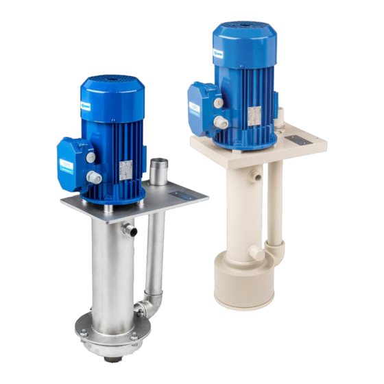
- Page 1 IOM manual CTV Vertical Centrifugal Pumps Original Instruction 2020 | 1 Read this instruction manual carefully, before you install and operate the pump. PP & PVDF Stainless steel CTV25-9 CTV20-9 CTV25-10 CTV25-9.8 CTV25-11 CTV40-12.5 CTV25-11.5 CTV40-13.5 CTV32-8.5 CTV32-10 CTV32-12.5...
-
Page 2: Table Of Contents
CONTENTS EC DECLARATION OF CONFORMITY 01/EC/CTV/2016 ................4 GENERAL ............................. 5 0.1. Introduction..........................5 0.2. Warning symbols ........................5 0.3. Qualification and training of personnel ................... 5 INSTALLATION ........................... 6 1.1. Operation principle ........................6 1.2. Receiving inspection ........................6 1.3. - Page 3 CONTENTS 2.3. Residual risks ..........................13 2.4. Disposal after expiration of the expected lifetime ............... 13 2.5. Waste of electrical and electronic equipment (WEEE) directive .......... 13 2.6. Actions in emergency ......................13 MAINTENANCE ..........................14 3.1. Inspections ..........................14 3.2.
-
Page 4: Ec Declaration Of Conformity 01/Ec/Ctv/2016
Member States relating to electrical equipment designed for use within certain voltage limits; Mr Michał Śmigiel is authorized to compile the technical file. Tapflo Sp. z o.o. ul. Czatkowska 4b 83-110 Tczew Signed for and on behalf of Tapflo AB: Håkan Ekstrand Managing director Tapflo AB, 16.04.2016... -
Page 5: General
This instruction manual will familiarise operators with detailed information about installing, operating and maintaining the pump. The CTV series are single-stage pumps with the pump casing directly submerged in the liquid. It is driven by an asynchronous electric motor. The inlet is located axially to the drive shaft, facing downwards and has a female BSP (plastic pumps) or male BSPT (metal pumps) threaded connection. -
Page 6: Installation
INSTALLATION INSTALLATION 1.1. Operation principle In order to operate the pump, the liquid level has to be above the impeller before start-up (for details see chapter 1.9 Example of installation). The rotating impeller generates a centrifugal force accelerating the liquid through the pump casing and into the discharge piping. -
Page 7: Installation
INSTALLATION Be careful that nobody passes under the pump when lifted. Never try to lift the pump by the manifolds or hoses attached to the pump. 1.5. Installation ➢ The CTV pump must be installed vertically and can be used in sumps, tanks and similar containers ➢... -
Page 8: Health And Safety
Any changes concerning the service of the pump as originally purchased, can be executed only after written approval from Tapflo. It is recommended to use only genuine Tapflo spare parts and approved accessories. The use of unoriginal spare parts or non-approved accessories will void warranty and remove any responsibility on our behalf for any damage caused to people or things. -
Page 9: Example Of Installation
INSTALLATION 1.9. Example of installation Flooded installation Installation with suction extension ➢ All installations: 1) Valve for flow control 2) Non-return valve (check valve) on discharge as close to the pump as possible 3) Connection point for pressure gauge or pressure switch 4) Divert discharge with 45°... -
Page 10: Instruments
INSTALLATION 1.10. Instruments In order to ensure a proper control of the performance and the conditions of the installed pump, we recommend using the following instruments: ➢ a pressure gauge on the discharge piping. The pressure gauge on discharge must always be fitted between the pump and the shut-off regulation valve. -
Page 11: Motor Standard
INSTALLATION 1.12. Motor standard As a standard Tapflo CTV pump are equipped with motors of the following parameters: ➢ International Mounting Arrangement – V1 ➢ Number of poles / Rotation speed [rpm] – 2 ➢ Non ATEX ➢ Protection grade – IP55 ➢... -
Page 12: Operation
OPERATION OPERATION 2.1. Start-up ➢ Check manually that the motor is free to turn, moving the motor cooling fan. ➢ Make sure that the piping is not clogged and is free from residues or foreign objects. ➢ The shut-off / regulation valve on the discharge side must be completely closed. ➢... -
Page 13: Residual Risks
OPERATION 2.3. Residual risks Even with proper application and observance of all points listed in this operating manual, there is still an estimable and unexpected residual risk when using the pumps. It may leak, fail due to wear, application-related causes or system-related circumstances. 2.4. -
Page 14: Maintenance
MAINTENANCE MAINTENANCE Maintenance work on electrical installations must be performed by qualified personnel and only when the power supply has been shutoff. Follow the local and national safety regulations. Wait five minutes for capacitor discharge before opening any equipment. 3.1. Inspections In general CTV range pumps do not require any maintenance. -
Page 15: Disassembly And Assembly Of The Pump
MAINTENANCE 3.3. Disassembly and assembly of the pump The disassembly should only be performed by qualified personnel. Each operation carried out on the machine must always be carried out once all the electrical contacts have been disconnected. The pump-motor unit must be placed in a position where it cannot be started unintentionally. - Page 16 MAINTENANCE Fig. 3.3.1.4 Remove the motor fan cover from the electric motor and then remove the motor fan. Fig 3.3.1.5 Secure the free end of the motor shaft using universal pliers or similar. Fig 3.3.1.6 Unscrew the impeller. Fig 3.3.1.7 Remove the impeller O-ring [193] from the impeller.
-
Page 17: 3.3.2. Assembly Of The Pump - Pp & Pvdf Pumps
MAINTENANCE Fig 3.3.1.9 Pull the shaft sleeve [162] from the motor shaft and then remove the lip seal [161]. Fig 3.3.1.10 Carefully push out the shaft bushing [15] from its seat by means of a screwdriver. Remove the O-ring [151] from the shaft bushing. - Page 18 MAINTENANCE Fig. 3.3.2.3 Screw the impeller screw [194] into the impeller [9…]. NOTE! Make sure to perform this procedure with care. Too much force applied while screwing in can damage the impeller. Fig. 3.3.2.4 Insert the O-ring [193] into the impeller [9…]. Fig.
- Page 19 MAINTENANCE Fig. 3.3.2.8 Insert the pump casing unit [11] on the motor shaft. Fig. 3.3.2.9 Using the special assembly tool [8-32-9XXX-MT] screw in the impeller [9…] onto the motor shaft. Note! Block the motor fan in order to perform this procedure.
- Page 20 MAINTENANCE Fig. 3.3.2.13 Screw the plug [22] onto the pump casing unit [11]. Note! Use PTFE tape on the thread. Fig. 3.3.2.14 Screw the elbow [17] into the pump casing unit [11]. Note! Use PTFE tape on the thread. Fig. 3.3.2.15 Screw the discharge pipe [12] into the elbow [17].
-
Page 21: Test Run
MAINTENANCE Fig. 3.3.2.16 Insert the stabilizer [202] on the discharge pipe [12] and fasten it with the hose clip [20]. Fig. 3.3.2.17 Put the casing O-ring [18] into the pump cover [1312]. Fig. 3.3.2.18 Screw the pump cover [1312] into the pump casing unit [11]. - Page 22 MAINTENANCE Fig. 3.3.4.2 Unscrew the casing mounting screws [141] with washers [142]. Fig. 3.3.4.3 Carefully lift off the pump cover [13] together with the elbow [17] and discharge pipe [12]. Fig. 3.3.4.4 Remove the casing O-ring [18]. NOTE! Always replace the casing O-ring after pump maintenance.
-
Page 23: Assembly Of The Pump
MAINTENANCE Fig 3.3.4.8 Remove the lip seal [161] from the motor shaft. Fig 3.3.4.9 Remove the motor fan cover from the electric motor and then remove the motor fan. Fig 3.3.4.10 Secure the free end of the motor shaft by means of universal pliers or similar. -
Page 24: 3.3.6. Test Run
MAINTENANCE Fig. 3.3.5.3 Use PTFE tape to tighten the connections between the pump cover [13], elbow [17] and discharge pipe [12]. 3.3.6. Test run We recommend you to conduct a test run of the pump before installing it in the system, so no liquid gets wasted if the pump leaks or perhaps does not start accordingly to wrong assembly of the pump. -
Page 25: Options
OPTIONS OPTIONS 4.1. Suction extension and strainer – 4E05, 4E10, 4S The pump can be delivered with a suction extension pipe. It is a great solution when there is a need to empty a tank or sump from a lower level than the immersion depth of the pump. -
Page 26: Left-Hand Thread On Pump Cover - 8L
OPTIONS 4.3. Left-hand thread on pump cover – 8L For plastic CTV pump there is an option of a left-hand thread on the pump cover. The thread can be differed from standard one with a cut on the socket. This way unscrewing of pump cover is avoided. This option is recommended especially when viscous liquids are pumped. -
Page 27: Spare Parts
SPARE PARTS SPARE PARTS 5.1. Spare parts – PP & PVDF pump 9... Q-ty Material Pos. Description Motor Pump casing unit PP, PVDF Discharge pipe PP, PVDF Motor mounting screw A4-70 Motor mounting washer A4-70 Motor mounting spring washer A4-80 1312 Pump cover PP, PVDF... -
Page 28: Spare Parts - Stainless Steel Pump
SPARE PARTS 5.2. Spare parts – stainless steel pump 9... Q-ty Material Pos. Description Motor Pump casing unit AISI 316L Discharge pipe AISI 316L Motor mounting screw A4-70 Motor mounting spring washer A4-80 Pump cover AISI 316L Casing mounting screw A4-70 Casing mounting washer A4-80... -
Page 29: Recommended Spare Parts
5.4. How to order parts When ordering spare parts for Tapflo pumps. please let us know what is the model number and serial number from the pump’s name plate. Then just indicate the part numbers from the spare parts list and quantity of each item. -
Page 30: Data
V. Motor power II. Pump size VI. Motor options III. Casing material IV. Special executions 25-10 CTV = Tapflo centrifugal vertical pump 6. Optional base plate Pump size (outlet mm – impeller cm): = Hendor style PP & PVDF Stainless steel... -
Page 31: Dimensions And Data - Pp & Pvdf Pumps
DATA 6.2. Dimensions and data – PP & PVDF pumps Dimensions in mm (inch) General dimensions only, ask us for detailed drawings. Changes reserved without notice. DIMENSION CTV 25 CTV 32 11.22 7.87 0,55 kW 7.72 0.75 kW ÷ 2.2 kW 8.66 3.35 3.74... -
Page 32: Dimensions And Data - Stainless Steel Pumps
DATA 6.3. Dimensions and data – Stainless steel pumps Dimensions in mm (inch) General dimensions only, ask us for detailed drawings. Changes reserved without notice. DIMENSION CTV 20 CTV 25 CTV 40 10.51 12.87 8.15 0,55 kW 8.43 0.75 kW ÷... -
Page 33: Performance Curves
DATA 6.4. Performance curves The performance curves are based on water at 0°C. Speed 2900 rpm. Contact us for detailed curves PP & PVDF pumps Stainless steel pumps IOM manual CTV vertical centrifugal pumps... -
Page 34: Permitted Loads On Inlet And Outlet
DATA 6.5. Permitted loads on inlet and outlet We recommend not to exceed the following loads and forces reacting on the inlet and outlet. CTV 25 – PP & PVDF Load [N] Moment of force Direction (inlet/outlet) (inlet/outlet) [Nm] CTP 32 – PP & PVDF Load [N] Moment of force Direction... -
Page 35: Warranty
7.2. Warranty Tapflo warrants products under conditions as stated below for a period of not more than 12 months from installation and not more than 24 months from date of manufacturing. 1. The following terms and conditions apply to the sale of machinery. components and related services and products. - Page 36 9. Tapflo will not be liable on any claim. whether in contact. tort. or otherwise. for any indirect. special. incidental. or consequential damages. caused to the customer or to third parties.
-
Page 37: Warranty Form
WARRANTY 7.3. Warranty form Company: Telephone: Fax: Address: Country: Contact Name: E-mail: Delivery Date: Date of pump installation: Pump type: Serial No (see name plate): Description of the fault: The installation: Liquid: Temperature [°C]: Viscosity [cPs]: Spec grav. [kg/m pH-value: Content of particles: %, of max size [mm]: Flow [l/min]:...
Need help?
Do you have a question about the CTV Series and is the answer not in the manual?
Questions and answers