GEM 615 Installation, Operating And Maintenance Instructions
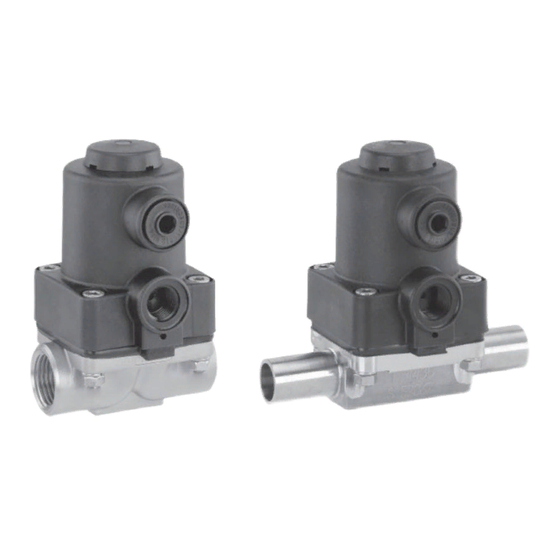
Diaphragm valve metal, dn 10 - 20
Hide thumbs
Also See for 615:
- Installation, operating and maintenance instructions (36 pages) ,
- Operating instructions manual (27 pages)

Related Manuals for GEM 615


Summary of Contents for GEM 615
- Page 1 Membranventil Metall, DN 10 - 20 Diaphragm Valve Metal, DN 10 - 20 ORIGINAL EINBAU- UND MONTAGEANLEITUNG INSTALLATION, OPERATING AND MAINTENANCE INSTRUCTIONS...
-
Page 2: Table Of Contents
Allgemeine Sicherheitshinweise 2 Sachgerechter Transport und Lagerung Hinweise für Service- Installation und Inbetriebnahme durch und Bedienpersonal eingewiesenes Fachpersonal Warnhinweise Bedienung gemäß dieser Einbau- und Verwendete Symbole Montageanleitung Begriff sbestimmungen Ordnungsgemäße Instandhaltung Vorgesehener Einsatzbereich Technische Daten Korrekte Montage, Bedienung und Wartung Bestelldaten oder Reparatur gewährleisten einen... -
Page 3: Hinweise Für Service
Möglicherweise gefährliche Situation! dürfen nicht ohne vorherige Abstimmung ® Bei Nichtbeachtung drohen mit dem Hersteller durchgeführt werden. Sachschäden. GEFAHR Sicherheitsdatenblätter bzw. die für die verwendeten Medien geltenden Sicherheitsvorschriften unbedingt beachten! Bei Unklarheiten: Bei nächstgelegener GEMÜ- Verkaufsniederlassung nachfragen. 3 / 36... -
Page 4: Verwendete Symbole
Vorgesehener Verwendete Symbole Einsatzbereich Gefahr durch heiße Oberflächen! Das GEMÜ-Membranventil 615 ist für den Einsatz in Rohrleitungen konzipiert. Gefahr durch ätzende Stoffe! Es steuert ein durchfließendes Medium indem es durch ein Steuermedium geschlossen oder geöffnet werden kann. Hand: Beschreibt allgemeine Das Ventil darf nur gemäß... -
Page 5: Technische Daten
Code 0 Code 16 Code 17 Code 18 Code 59 Code 60 Kv-Werte ermittelt gemäß DIN EN 60534, Eingangsdruck 6 bar, Δp 1 bar, Ventilkörperwerkstoff Edelstahl und Weichelastomermembrane. Steuer- / Betriebsdruckdiagramm Stf. 2 Stf. 2 Stf. 3 Stf. 3 Betriebsdruck [bar]... -
Page 6: Bestelldaten
Bestelldaten Gehäuseform Code Ventilkörperwerkstoff Code Durchgang CW617N (Messing) 1.4435 - BN2 (CF3M) - Feinguss Fe<0,5% Anschlussart Code 1.4435 (ASTM A 351 CF3M ≙ 316L), Feinguss Schweißstutzen 1.4408, Feinguss Stutzen DIN 1.4435 (316 L), Schmiedekörper Stutzen DIN 11850, Reihe 1 Stutzen DIN 11850, Reihe 2 1.4435 (BN2), Schmiedekörper Fe<0,5% Stutzen DIN 11850, Reihe 3 1.4539, Schmiedekörper... -
Page 7: Herstellerangaben
Herstellerangaben Funktionsbeschreibung GEMÜ 615 ist ein Metall-Membranventil Transport mit Durchgangskörper. Das Ventil besitzt einen wartungsarmen Kolbenantrieb, Membranventil nur auf geeignetem der mit neutralen Gasen angesteuert Lademittel transportieren, nicht stürzen, werden kann, und eine integrierte vorsichtig handhaben. optische Stellungsanzeige. Ventilkörper Verpackungsmaterial entsprechend und Membrane sind gemäß... -
Page 8: Montage Und Bedienung
Schutzmaßnahmen vermeiden. des Ventilkörpers demontieren (siehe Kapitel 11.1). Montagearbeiten nur durch geschultes 3. Schweißstutzen abkühlen lassen. Fachpersonal. 4. Ventilkörper und Antrieb mit Membrane Geeignete Schutzausrüstung gemäß wieder zusammen bauen (siehe Kapitel den Regelungen des Anlagenbetreibers 11.4). berücksichtigen. 8 / 36... -
Page 9: Bedienung
10.2 Bedienung Montage bei Clampanschluss: Bei Montage der Clampanschlüsse Optische Stellungsanzeige entsprechende Dichtung zwischen Ventilkörper und Rohranschluss einlegen und mit Klammer verbinden. Die Dichtung sowie die Klammer der Clampanschlüsse sind nicht im Lieferumfang enthalten. Wichtig: Schweißstutzen / Clampanschlüsse: Drehwinkel für das entleerungsoptimierte Einschweißen entnehmen Sie bitte Ventil off... -
Page 10: Steuermedium Anschließen
Verschmutzungen reinigen. Teile dabei Beidseitig 2: Steuermedium (Öffnen) nicht zerkratzen oder beschädigen! angesteuert (DA) 4: Steuermedium (Schließen) 3. Alle Teile auf Beschädigungen prüfen. Anschlüsse 2 / 4 siehe Foto oben 4. Beschädigte Teile austauschen (nur Originalteile von GEMÜ verwenden). 10 / 36... -
Page 11: Montage Membrane
11.3 Montage Membrane Das Druckstück ist lose. Druckstück und Antriebsflansch von unten 11.3.1 Allgemeines gesehen: Wichtig: Für Ventil passende Membrane einbauen (geeignet für Medium, Mediumkonzentration, Temperatur und Druck). Die Absperrmembrane ist ein Verschleißteil. Vor Druckstück - Ansicht von Membranseite Inbetriebnahme und über gesamte Einsatzdauer des Membranventils technischen Zustand und Funktion überprüfen. -
Page 12: Montage Der Konkav-Membrane
Muttern 20 (siehe Kapitel 19 Druckstückaussparung liegt. "Schnittbild und Ersatzteile") 6. Bei Schwergängigkeit Gewinde prüfen, nachziehen. beschädigte Teile austauschen (nur Originalteile von GEMÜ verwenden). 7. Beim Verspüren eines deutlichen Widerstands Membrane soweit zurückschrauben, bis Membran-Lochbild mit Antriebs-Lochbild übereinstimmt. 12 / 36... -
Page 13: Inbetriebnahme
Membranventil auf Dichtheit und Funktion GEMÜ keinerlei Haftung. prüfen (Membranventil schließen und Nehmen Sie im Zweifelsfall vor wieder öffnen). Inbetriebnahme Kontakt mit GEMÜ auf. Bei neuen Anlagen und nach Reparaturen Leitungssystem bei voll 1. Geeignete Schutzausrüstung gemäß geöffnetem Membranventil spülen (zum den Regelungen des Anlagenbetreibers Entfernen schädlicher Fremdstoffe). -
Page 14: Demontage
2014/34/EU (ATEX Richtlinie): Membranventil demontieren (siehe Ein Beiblatt zur Richtlinie Kapitel 11.1 "Demontage Ventil 2014/34/EU liegt dem Produkt bei, (Antrieb vom Körper lösen)"). sofern es gemäß ATEX bestellt Leitung(en) des Steuermediums wurde. abschrauben (siehe Kapitel 11.4 "Steuermedium anschließen"). Hinweis zur... -
Page 15: Fehlersuche / Störungsbehebung
Fehlersuche / Störungsbehebung Fehler Möglicher Grund Fehlerbehebung Steuermedium entweicht aus Anschluss 4* (bei Steuerfunktion NC) Antriebskolben defekt Antrieb austauschen bzw. Anschluss 2* (bei Steuerfunktion NO) Steuermedium entweicht Antrieb austauschen und Steuermedium Spindelabdichtung undicht aus Leckagebohrung* auf Verschmutzungen untersuchen Betriebsmedium Absperrmembrane auf Beschädigungen entweicht aus Absperrmembrane defekt prüfen, ggf. -
Page 16: Schnittbild Und Ersatzteile
Schnittbild und Ersatzteile Anschluss 4 Anschluss 2 Leckagebohrung Pos. Benennung Bestellbezeichnung Ventilkörper K612... Membrane 600 10M... Schraube Scheibe 615 S30... Mutter Antrieb 9615... 16 / 36... -
Page 17: Einbauerklärung
4.1.2.6. c); 4.1.2.6. d); 4.1.2.6. e); 4.1.3.; 4.2.1.; 4.2.1.4.; 4.2.2.; 4.2.3.; 4.3.1.; 4.3.2.; 4.3.3.; 4.4.1.; 4.4.2.; 5.3.; 5.4.; 6.1.1.; 6.3.3.; 6.4.1.; 6.4.3. Ferner wird erklärt, dass die speziellen technischen Unterlagen gemäß Anhang VII Teil B erstellt wurden. Es wird ausdrücklich erklärt, dass die unvollständige Maschine allen einschlägigen Bestimmungen... - Page 18 Contents General information General information Prerequisites to ensure that the GEMÜ valve General safety information functions correctly: Information for service Correct transport and storage and operating personnel Installation and commissioning by trained Warning notes personnel Symbols used Operation according to these installation, Defi...
-
Page 19: Information For Service And Operating Personnel
® Non-observance can cause damage to be performed without consulting the property. manufacturer first. DANGER Strictly observe the safety data sheets or the safety regulations that are valid for the media used. In cases of uncertainty: Consult the nearest GEMÜ sales office. 19 / 36... -
Page 20: Symbols Used
Intended area of use Symbols used The GEMÜ 615 diaphragm valve is Danger - hot surfaces! designed for installation in piping systems. It controls a flowing medium by being opened or closed by a control Danger - corrosive materials! medium. -
Page 21: Technical Data
Technical data Working medium Corrosive, inert, gaseous and liquid media which have no negative impact on the physical and chemical properties of the body and diaphragm material. Temperatures Media temperature -10 to 80 °C Ambient temperature 0 to 60 °C Control medium Inert gases Max. -
Page 22: Order Data
Order data Body configuration Code Valve body material Code 2/2-way body CW617N (Brass) 1.4435 - BN2 (CF3M), investment casting Fe<0.5% Connection Code 1.4435 (ASTM A 351 CF3M ≙ 316L), investment casting 34 Butt weld spigots 1.4408, investment casting Spigots DIN 1.4435 (316 L), forged body Spigots DIN 11850, series 1 Spigots DIN 11850, series 2... -
Page 23: Manufacturer's Information
Manufacturer’s information Functional description GEMÜ 615 is a metal diaphragm valve Transport with a 2/2-way body. The valve has a low maintenance piston actuator which can be Only transport the diaphragm valve by controlled by inert gases and an integral suitable means. -
Page 24: Installation And Operation
Installation and operation Installation location: CAUTION Prior to installation: Ensure that valve body and diaphragm Do not apply external force to the valve. material are appropriate and compatible Choose the installation location so that to handle the working medium. the valve cannot be used as a foothold See chapter 5 "Technical data". -
Page 25: Operation
10.2 Operation Installation - Clamp connections: When installing clamp connections, Optical position indicator insert a gasket between the body clamp and the adjacent piping clamp and join them using the appropriate clamp fitting. The gasket and the clamp for clamp connections are not included in the scope of delivery. -
Page 26: Connecting The Control Medium
(do not damage control medium parts). Check parts for potential damage, replace if necessary (only Important: use genuine parts from GEMÜ). Connect the control medium lines tension-free and without any bends or knots! Use appropriate connectors according to the application. -
Page 27: Removing The Diaphragm
Compressor and actuator flange seen from 3. Check all parts for potential damage. below: 4. Replace damaged parts (only use genuine parts from GEMÜ). 11.3 Mounting the diaphragm 11.3.1 General information Compressor - view from diaphragm side... -
Page 28: Actuator Mounting On Valve Body
6. If it is difficult to screw it in, check the parts"). thread, replace damaged parts (only use genuine parts from GEMÜ). 7. When clear resistance is felt turn back the diaphragm anticlockwise until its bolt holes are in correct alignment with the bolt holes of the actuator. -
Page 29: Commissioning
(water hammer). by improper handling or third-party actions. Prior to cleaning or commissioning the In case of doubt, contact GEMÜ before plant: commissioning. Check the tightness and the function of the diaphragm valve (close and reopen 1. -
Page 30: Disassembly
Clean the valve. Request a goods return declaration form from GEMÜ. Returns must be made with a completed declaration of return. If not completed, GEMÜ cannot process credits or repair work but will dispose of the goods at the operator's expense. -
Page 31: Troubleshooting / Fault Clearance
Troubleshooting / Fault clearance Fault Possible cause Fault clearance Control medium escapes from connector 4* (control function Actuator piston faulty Replace actuator NC) or from connector 2* (control function NO) Control medium escapes from Replace actuator and check control Spindle seal leaking leak detection hole* medium for impurities Working medium escapes... -
Page 32: Sectional Drawing And Spare Parts
Sectional drawing and spare parts Connector 4 Connector 2 Leak detection hole Item Name Order description Valve body K612... Diaphragm 600 10M... Bolt Washer 615 S30... Actuator 9615... 32 / 36... -
Page 33: Declaration Of Incorporation
Declaration of Incorporation according to the EC Machinery Directive 2006/42/EC, Annex II, 1.B for partly completed machinery Manufacturer: GEMÜ Gebr. Müller Apparatebau GmbH & Co. KG Postfach 30 Fritz-Müller-Straße 6-8 D-74653 Ingelfingen-Criesbach Description and identification of the partly completed machinery: Make: GEMÜ... - Page 34 34 / 36...
- Page 35 35 / 36...
- Page 36 GEMÜ Gebr. Müller Apparatebau GmbH & Co. KG · Fritz-Müller-Str. 6-8 · D-74653 Ingelfi ngen-Criesbach Telefon +49(0)7940/123-0 · Telefax +49(0)7940/123-192 · info@gemue.de · www.gemu-group.com...
Need help?
Do you have a question about the 615 and is the answer not in the manual?
Questions and answers