GEM 615 Operating Instructions Manual
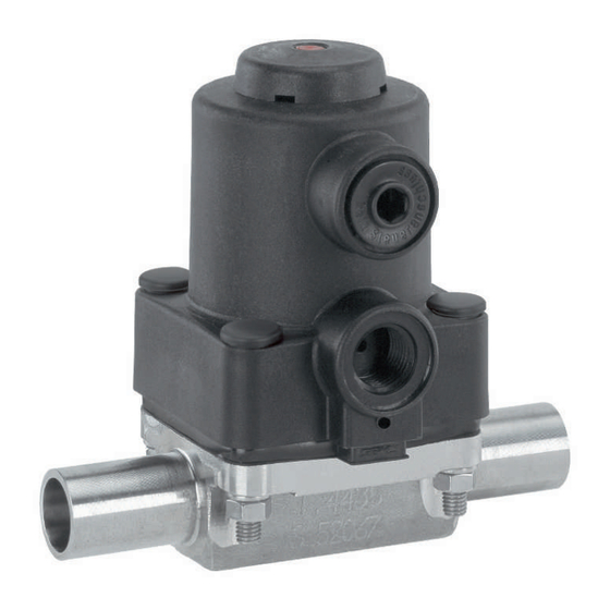
Pneumatically operated diaphragm valve
Hide thumbs
Also See for 615:

Subscribe to Our Youtube Channel
Related Manuals for GEM 615


Summary of Contents for GEM 615
- Page 1 GEMÜ 615 Pneumatically operated diaphragm valve Operating instructions further information webcode: GW-615...
- Page 2 All rights including copyrights or industrial property rights are expressly reserved. Keep the document for future reference. © GEMÜ Gebr. Müller Apparatebau GmbH & Co. KG 28.04.2023 GEMÜ 615 2 / 27 www.gemu-group.com...
-
Page 3: Table Of Contents
Warning notes ..........2 Safety information ..........3 Product description ..........Construction ..........Description ............. Function ............Product label ..........4 GEMÜ CONEXO ............ 5 Order data ............6 Technical data ............. Medium ............Temperature ..........Pressure ............Product conformity ........ -
Page 4: General Information
Symbol Meaning 1.3 Definition of terms Corrosive chemicals! Working medium The medium that flows through the GEMÜ product. Control function Hot plant components! The possible actuation functions of the GEMÜ product. Control medium The medium whose increasing or decreasing pressure causes the GEMÜ... -
Page 5: Safety Information
In cases of uncertainty: 3.2 Description 15. Consult the nearest GEMÜ sales office. The GEMÜ 615 2/2-way diaphragm valve has a low-mainten- ance plastic piston actuator and is pneumatically operated. An integrated optical position indicator is standard. Normally Closed (NC), Normally Open (NO) and Double Acting (DA) con- trol functions are available. -
Page 6: Function
The month of manufacture is encoded in the traceability num- the maintenance process much more transparent and easier ber and can be obtained from GEMÜ. The product was manu- to document. The app actively guides the maintenance techni- factured in Germany. -
Page 7: Order Data
D mechanically polished internal Clamp DIN 32676 series C, Ra ≤ 0.6 µm (25 µin.) for media wetted surfaces, 1508 face-to-face dimension FTF ASME BPE, electropolished internal/external length only for body configuration D www.gemu-group.com 7 / 27 GEMÜ 615... - Page 8 8 Actuator version Actuator size 1/N 9 Surface 1500 Ra ≤ 6.3 μm (250 μin.) for media wetted surfaces, mechanically polished internal 10 Special version Special version for oxygen, maximum medium temperature: 60 °C 11 CONEXO Without GEMÜ 615 8 / 27 www.gemu-group.com...
-
Page 9: Technical Data
-10 — 80 °C PTFE/EPDM (code 54) -10 — 80 °C 0 — 60 °C Ambient temperature: 0 — 60 °C Control medium temper- 0 — 40 °C ature: Storage temperature: 0 — 40 °C www.gemu-group.com 9 / 27 GEMÜ 615... -
Page 10: Pressure
In general, all diaphragms are subject to the influences of pressure, temperature, the process and their tightening torques. Therefore the Kv values may exceed the tolerance limits of the stand- ard. GEMÜ 615 10 / 27 www.gemu-group.com... -
Page 11: Product Conformity
0, 16, 17, 18, 6, 6K 80, 82, 88, 8A, 36, 55, 59, 60, 8P, 8T 63, 64, 65 0.30 0.33 0.30 0.17 0.30 0.26 0.35 0.43 0.43 Weights in kg MG = diaphragm size www.gemu-group.com 11 / 27 GEMÜ 615... -
Page 12: Dimensions
7 Dimensions 7 Dimensions 7.1 Actuator dimensions ØB ø B 80.0 21.0 30.0 57.0 35.0 68.0 G 1/4 M12x1 Dimensions in mm MG = diaphragm size * CT = A + H1 (see body dimensions) GEMÜ 615 12 / 27 www.gemu-group.com... -
Page 13: Body Dimensions
Code 17: Spigot EN 10357 series A/DIN 11866 series A formerly DIN 11850 series 2 Code 60: Spigot ISO 1127/EN 10357 series C/DIN 11866 series B 2) Valve body material Code C3: 1.4435, investment casting www.gemu-group.com 13 / 27 GEMÜ 615... - Page 14 Code 65: Spigot ANSI/ASME B36.19M schedule 40s 2) Valve body material Code 40: 1.4435 (F316L), forged body Code 42: 1.4435 (BN2), forged body, Δ Fe < 0.5% Code C3: 1.4435, investment casting Code F4: 1.4539, forged body GEMÜ 615 14 / 27 www.gemu-group.com...
- Page 15 Dimensions in mm MG = diaphragm size n = number of flats 1) Connection type Code 1: Threaded socket DIN ISO 228 2) Valve body material Code 12: CW614N, CW617N (brass) Code 37: 1.4408, investment casting www.gemu-group.com 15 / 27 GEMÜ 615...
- Page 16 MG = diaphragm size 1) Connection type Code 6K: Cone spigot and union nut DIN 11851 2) Valve body material Code 40: 1.4435 (F316L), forged body Code 42: 1.4435 (BN2), forged body, Δ Fe < 0.5% GEMÜ 615 16 / 27 www.gemu-group.com...
- Page 17 108.0 108.0 Dimensions in mm MG = diaphragm size 1) Valve body material Code 40: 1.4435 (F316L), forged body Code 42: 1.4435 (BN2), forged body, Δ Fe < 0.5% Code F4: 1.4539, forged body www.gemu-group.com 17 / 27 GEMÜ 615...
-
Page 18: Manufacturer's Information
"Technical data"). operating conditions (medium, medium concentration, temperature and pressure) and the prevailing ambient 4. Do not store solvents, chemicals, acids, fuels or similar conditions. fluids in the same room as GEMÜ products and their spare parts. NOTICE 8.4 Delivery Tools ●... -
Page 19: Installation With Butt Weld Spigots
Retighten the bolts and nuts at the very latest after the ● first sterilization process. ● Re-attach or reactivate all safety and protective devices. Fig. 3: Threaded socket www.gemu-group.com 19 / 27 GEMÜ 615... -
Page 20: Operation
Control function 2: connector 2 is closed with a blanking plug. Control function Connectors 1 (NC) 2 (NO) 3 (DA) + = available / - = not available (see figure for connectors 2 / 4) GEMÜ 615 20 / 27 www.gemu-group.com... -
Page 21: Connecting The Control Medium
(water hammer). CAUTION Cleaning agent ▶ Damage to the GEMÜ product. The plant operator is responsible for selecting the clean- ● ing material and performing the procedure. 1. Check the tightness and the function of the product (close and reopen the product). -
Page 22: Troubleshooting
Tighten threaded connections / unions Sealing material faulty Replace sealing material Valve body is leaking Valve body is leaking Check valve body for damage, replace valve body if necessary * see chapter "Spare parts" GEMÜ 615 22 / 27 www.gemu-group.com... -
Page 23: Inspection And Maintenance
● by trained personnel. 2. Remove the actuator A from the valve body 1. Do not extend hand lever. GEMÜ shall assume no liability ● 3. Move the actuator A to the closed position. whatsoever for damages caused by improper handling or third-party actions. - Page 24 6. If it is difficult to screw it in, check the thread, replace Anti-twist damaged parts (only use genuine parts from GEMÜ). system 7. When clear resistance is felt, turn back the diaphragm an- ticlockwise until its bolt holes are in correct alignment with the bolt holes of the actuator.
-
Page 25: Removal From Piping
Returned goods can be processed only when this note is completed. If no return delivery note is included with the product, GEMÜ cannot process credits or repair work but will dispose of the goods at the operator's expense. -
Page 26: Eu Declaration Of Incorporation According To The Ec Machinery Directive 2006/42/Ec, Annex Ii B
Declaration of Incorporation according to the EC Machinery Directive 2006/42/EC, Annex II, 1.B for partly completed machinery Manufacturer: GEMÜ Gebr. Müller Apparatebau GmbH & Co. KG Postfach 30 Fritz-Müller-Straße 6-8 D-74653 Ingelfingen-Criesbach Description and identification of the partly completed machinery: Make: GEMÜ... - Page 27 GEMÜ Gebr. Müller Apparatebau GmbH & Co. KG Fritz-Müller-Straße 6-8, 74653 Ingelfingen-Criesbach, Germany Subject to alteration Phone +49 (0) 7940 1230 · info@gemue.de www.gemu-group.com 04.2023 | 88860157...
Need help?
Do you have a question about the 615 and is the answer not in the manual?
Questions and answers