GEM 615 Installation, Operating And Maintenance Instructions
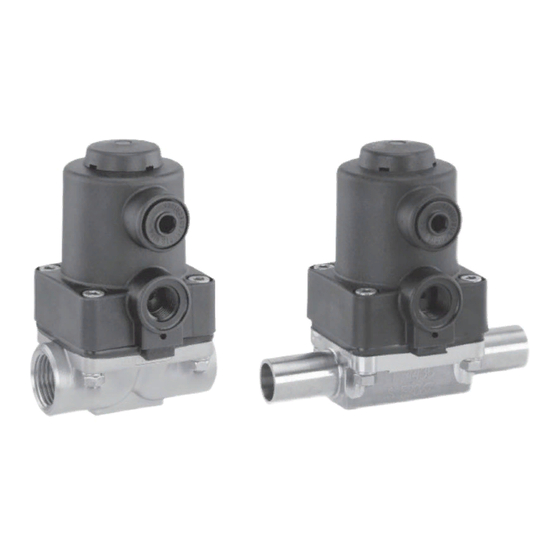
Diaphragm valve metal, dn 10 - 20
Hide thumbs
Also See for 615:
- Installation, operating and maintenance instructions (36 pages) ,
- Operating instructions manual (27 pages)

Related Manuals for GEM 615


Summary of Contents for GEM 615
- Page 1 Membranventil Metall, DN 10 - 20 Diaphragm Valve Metal, DN 10 - 20 ORIGINAL EINBAU- UND MONTAGEANLEITUNG INSTALLATION, OPERATING AND MAINTENANCE INSTRUCTIONS 615_us...
-
Page 2: Table Of Contents
Funktion des GEMÜ-Ventils: Hinweise für Service- Sachgerechter Transport und Lagerung. und Bedienpersonal Installation und Inbetriebnahme durch Warnhinweise eingewiesenes Fachpersonal. Verwendete Symbole Bedienung gemäß dieser Einbau- und Begriff sbestimmungen Montageanleitung. Vorgesehener Einsatzbereich Ordnungsgemäße Instandhaltung. Auslieferungszustand Korrekte Montage, Bedienung und Wartung Technische Daten... -
Page 3: Hinweise Für Service
Montageanleitung beschrieben sind ® Bei Nichtbeachtung drohen dürfen nicht ohne vorherige Abstimmung Sachschäden. mit dem Hersteller durchgeführt werden. GEFAHR Sicherheitsdatenblätter bzw. die für die verwendeten Medien geltenden Sicherheitsvorschriften unbedingt beachten! Bei Unklarheiten: Bei nächstgelegener GEMÜ- Verkaufsniederlassung nachfragen. 615_us 3 / 36... -
Page 4: Verwendete Symbole
Verwendete Symbole Vorgesehener Einsatzbereich Das GEMÜ-Membranventil 615 ist für Gefahr durch heiße Oberfl ächen! den Einsatz in Rohrleitungen konzipiert. Es steuert ein durchfl ießendes Medium indem es durch ein Steuermedium Gefahr durch ätzende Stoff e! geschlossen oder geöff net werden kann. -
Page 5: Technische Daten
Reihe 2 Reihe 3 Code 0 Code 16 Code 17 Code 18 Code 59 Code 60 Kv-Werte ermittelt gemäß Norm IEC 534, Eingangsdruck 6 bar, Δp 1 bar, Ventilkörperwerkstoff Edelstahl und Weichelastomermembrane. Steuer- / Betriebsdruckdiagramm Betriebsdruck (bar) 615_us 5 / 36... -
Page 6: Bestelldaten
Bestelldaten Gehäuseform Code Ventilkörperwerkstoff Code Durchgang MS, Messing 1.4435 - BN2 (CF3M) - Feinguss Fe<0,5% 1.4435 (ASTM A 351 CF3M ≙ 316L), Feinguss 1.4435 (316 L), Schmiedekörper Anschlussart Code 1.4435 (BN2), Schmiedekörper Fe<0,5% Schweißstutzen Stutzen DIN Stutzen DIN 11850, Reihe 1 Stutzen DIN 11850, Reihe 2 Membranwerkstoff... -
Page 7: Herstellerangaben
Herstellerangaben Funktionsbeschreibung GEMÜ 615 ist ein Metall-Membranventil mit Durchgangskörper. Das Ventil besitzt einen Transport wartungsarmen Kolbenantrieb, der mit neu- Membranventil nur auf geeignetem tralen Gasen angesteuert werden kann, und Lademittel transportieren, nicht stürzen, eine integrierte optische Stellungsanzeige. vorsichtig handhaben. Ventilkörper und Membrane sind gemäß... -
Page 8: Montage Und Bedienung
Schutzmaßnahmen vermeiden. des Ventilkörpers demontieren (siehe Kapitel 12.1). Montagearbeiten nur durch geschultes 3. Schweißstutzen abkühlen lassen. Fachpersonal. 4. Ventilkörper und Antrieb mit Membrane Geeignete Schutzausrüstung gemäß wieder zusammen bauen (siehe Kapitel den Regelungen des Anlagenbetreibers 12.4). berücksichtigen. 615_us 8 / 36... -
Page 9: Bedienung
11.2 Bedienung Montage bei Clampanschluss: Bei Montage der Clampanschlüsse Optische Stellungsanzeige entsprechende Dichtung zwischen Ventilkörper und Rohranschluss einlegen und mit Klammer verbinden. Die Dichtung sowie die Klammer der Clampanschlüsse sind nicht im Lieferumfang enthalten. Wichtig: Schweißstutzen / Clampanschlüsse: Drehwinkel für das entleerungs- optimierte Einschweißen entnehmen Sie bitte der Broschüre "Drehwinkel für 2/2-Wege-Ventilkörper"... -
Page 10: Steuermedium Anschließen
Nach Demontage alle Teile von Ver- schmutzungen reinigen (Teile dabei Wichtig: nicht beschädigen). Teile auf Be- Steuermediumleitungen span- schädigung prüfen, ggf. auswech- nungs- und knickfrei montieren! seln (nur Originalteile von GEMÜ Je nach Anwendung geeignete verwenden). Anschlussstücke verwenden. Gewinde des Steuermediumanschlusses: G1/4 Steuerfunktion... -
Page 11: Demontage Membrane
Ventilsitz. Die Funktion des Ventils 3. Alle Teile auf Beschädigungen prüfen. ist nicht mehr gewährleistet. 4. Beschädigte Teile austauschen (nur Originalteile von GEMÜ verwenden). Das Druckstück ist lose. 12.3 Montage Membrane Druckstück und Antriebsfl ansch von unten gesehen: 12.3.1 Allgemeines... -
Page 12: Montage Der Konkav-Membrane
Ventils unbe- 6. Bei Schwergängigkeit Gewinde prüfen, dingt Muttern 20 (siehe Kapitel 20 beschädigte Teile austauschen (nur "Schnittbild und Ersatzteile") nach- Originalteile von GEMÜ verwenden). ziehen. 7. Beim Verspüren eines deutlichen Widerstands Membrane soweit zurück- schrauben, bis Membran-Lochbild mit Antriebs-Lochbild übereinstimmt. -
Page 13: Inbetriebnahme
Anlage: GEMÜ keinerlei Haftung. Membranventil auf Dichtheit und Funktion Nehmen Sie im Zweifelsfall vor prüfen (Membranventil schließen und Inbetriebnahme Kontakt mit GEMÜ auf. wieder öff nen). Bei neuen Anlagen und nach 1. Geeignete Schutzausrüstung gemäß Reparaturen Leitungssystem bei voll den Regelungen des Anlagenbetreibers geöff... -
Page 14: Demontage
(ATEX Richtlinie): Membranventil demontieren (siehe Ein Beiblatt zur Richtlinie 94/9/EG Kapitel 12.1 "Demontage Ventil (Antrieb liegt dem Produkt bei, sofern es vom Körper lösen)"). gemäß ATEX bestellt wurde. Leitung(en) des Steuermediums abschrauben (siehe Kapitel 11.4 Hinweis zur Mitarbeiter- "Steuermedium anschließen"). schulung: Zur Mitarbeiterschulung nehmen Sie bitte über die Adresse auf der... -
Page 15: Fehlersuche / Störungsbehebung
19 Fehlersuche / Störungsbehebung Fehler Möglicher Grund Fehlerbehebung Steuermedium entweicht aus Anschluss 4* (bei Steuerfunk- Steuerkolben defekt Antrieb austauschen tion 1 (NC)) bzw. Anschluss 2* (bei Steuerfunktion 2 (NO)) Steuermedium entweicht aus Antrieb austauschen und Steuermedium Spindelabdichtung undicht Leckagebohrung* auf Verschmutzungen untersuchen Betriebsmedium entweicht Absperrmembrane auf Beschädigungen Absperrmembrane defekt... -
Page 16: Schnittbild Und Ersatzteile
20 Schnittbild und Ersatzteile Anschluss 4 Anschluss 2 Leckagebohrung Pos. Benennung Bestellbezeichnung Ventilkörper K612... Membrane 600 10M... Schraube Scheibe 615 S30... Mutter Antrieb 9615... 615_us 16 / 36... -
Page 17: Einbauerklärung
4.1.2.6. c); 4.1.2.6. d); 4.1.2.6. e); 4.1.3.; 4.2.1.; 4.2.1.4.; 4.2.2.; 4.2.3.; 4.3.1.; 4.3.2.; 4.3.3.; 4.4.1.; 4.4.2.; 5.3.; 5.4.; 6.1.1.; 6.3.3.; 6.4.1.; 6.4.3. Ferner wird erklärt, dass die speziellen technischen Unterlagen gemäß Anhang VII Teil B erstellt wurden. Es wird ausdrücklich erklärt, dass die unvollständige Maschine allen einschlägigen Bestimmungen... - Page 18 12.3.2 Mounting a concave diaphragm additional assembly personnel. 12.4 Actuator mounting on the valve body Commissioning Important: Inspection and servicing The GEMÜ valve is sold to Disassembly sophisticated users. Training Disposal regarding safety issues must be Returns undertaken by each user. Information...
-
Page 19: Notes For Servicing And Operating Personnel
DANGER Strictly observe the safety data sheets or the safety regulations valid for the media used. In case of uncertainty Consult the nearest GEMÜ sales offi ce. 615_us 19 / 36... -
Page 20: Symbols Used
Control function conditions specifi ed in the contract The possible diff erent actuation functions of documentation and operating the diaphragm valve. instructions. Delivery condition The GEMÜ diaphragm valve is supplied as a separately packed component. 615_us 20 / 36... -
Page 21: Technical Data
Technical data Working medium Control medium Corrosive, inert, gaseous and liquid media which have no Inert gases negative impact on the physical and chemical properties of Max. perm. temperature of control medium 40° C the body and diaphragm material. Filling volume 0.02 dm³... -
Page 22: Order Data
Order data Body confi guration Code Valve body material Code 2/2-way body MS, brass 1.4435 - BN2 (CF3M), investment casting Fe<0.5% 1.4435 (ASTM A 351 CF3M ≙ 316L), investment casting 1.4435 (316 L), forged body Connection Code 1.4435 (BN2), forged body Fe<0.5% Butt weld spigots Spigots DIN Spigots DIN 11850, series 1... -
Page 23: Manufacturer's Information
Manufacturer’s information Functional description GEMÜ 615 is a metal diaphragm valve with a 2/2-way body. The valve has a low Transport maintenance piston actuator which can be controlled by inert gases and an integral Only transport the diaphragm valve optical position indicator. The valve body by suitable means. -
Page 24: Installation And Operation
11 Installation and operation Installation work may only be performed by trained personnel. Prior to installation: Ensure that valve body and diaphragm Use appropriate protective gear as material are appropriate and compatible specifi ed in plant operator's guidelines. to handle the working medium. Installation location: Check the suitability prior to the installation. -
Page 25: Operation
Installation - Butt weld spigots: After the installation: 1. Adhere to good welding practices! Important: 2. Remove the actuator with the diaphragm Diaphragms loose seal compression before welding the valve body into the in the course of time. After valve pipeline (see chapter 12.1). -
Page 26: Connecting The Control Medium
Control function 3 Always make sure you have used the Double acting (DA): correct threads. Failure to do so could cause Valve resting position: no defi ned normal the control media line to hit someone with position. The valve is opened and closed force (due to compressed control medium), by activating the respective control medium thereby causing death or serious injury. -
Page 27: Removing The Diaphragm
(suitable for medium, parts). Check parts for potential medium concentration, temperature damage, replace if necessary (only and pressure). The diaphragm is a use genuine parts from GEMÜ). wearing part. Check the technical condition function diaphragm valve before commissioning 12.2 Removing the diaphragm... -
Page 28: Mounting A Concave Diaphragm
20 (see thread, replace damaged parts (only use chapter 20 "Sectional drawing and genuine parts from GEMÜ). spare parts"). Bolt tightness / valve 7. When clear resistance is felt turn back sealing should be checked on a... -
Page 29: Commissioning
If the plant is new and after repairs rinse actions. the piping system with a fully opened In case of doubt, contact GEMÜ before diaphragm valve (to remove any harmful commissioning. foreign matter). Cleaning:... -
Page 30: Disassembly
17 Returns Clean the diaphragm valve. Returns must be made with a completed declaration of return (included). If not completed, GEMÜ cannot process credits or repair work but will dispose of the goods at the operator's expense. Note for returns:... -
Page 31: Troubleshooting / Fault Clearance
Troubleshooting / Fault clearance Fault Possible cause Fault clearance Control medium escapes from connector 4* (control function Control piston faulty Replace actuator 1 (NC)) or from connector 2* (control function 2 (NO)) Control medium escapes from Replace actuator and check control Spindle seal leaking leak detection hole* medium for impurities... -
Page 32: Sectional Drawing And Spare Parts
20 Sectional drawing and spare parts Connector 4 Connector 2 Leak detection hole Item Name Order description Valve body K612... Diaphragm 600 10M... Bolt Washer 615 S30... Actuator 9615... 615_us 32 / 36... -
Page 33: Declaration Of Incorporation
Declaration of Incorporation according to the EC Machinery Directive 2006/42/EC, Annex II, 1.B for partly completed machinery Manufacturer: GEMÜ Gebr. Müller Apparatebau GmbH & Co. KG Postfach 30 Fritz-Müller-Straße 6-8 D-74653 Ingelfingen-Criesbach Description and identification of the partly completed machinery: Make: GEMÜ... - Page 34 Rücksendeerklärung (Kopiervorlage) Gesetzliche Bestimmungen, der Schutz der Umwelt und des Personals erfordern es, diese Erklärung vollständig ausgefüllt und unterschrieben den Versandpapieren beizulegen. Wenn diese Erklärung nicht vollständig ausgefüllt ist oder den Versandpapieren nicht beigelegt ist wird Ihre Rücksendung nicht bearbeitet! Wurde das Ventil / Gerät mit giftigen, ätzenden, brennbaren, aggressiven oder wassergefährdenden Medien betrieben, alle mediumsberührten Teile sorgfältig entleeren, dekontaminieren und spülen.
-
Page 35: Goods Return Declaration
Goods return declaration (copy specimen) Legal regulations for the protection of the environment and personnel require that you include the completed and signed goods return declaration with your dispatch documents. If this declaration is not completed or not included with the dispatch documents, your return will not be processed! If the valve / device was operated with poisonous, corrosive, flammable, aggressive or water- endangering media, all medium wetted parts must be emptied carefully, decontaminated and rinsed. - Page 36 VENTIL-, MESS- UND REGELSYSTEME VALVES, MEASUREMENT AND CONTROL SYSTEMS GEMÜ Gebr. Müller Apparatebau GmbH & Co. KG · Fritz-Müller-Str. 6-8 · D-74653 Ingelfi ngen-Criesbach Telefon +49(0)7940/123-0 · Telefax +49(0)7940/123-192 · info@gemue.de · www.gemue.de...
Need help?
Do you have a question about the 615 and is the answer not in the manual?
Questions and answers