Table of Contents
Advertisement
Quick Links
One Technology Way • P.O. Box 9106 • Norwood, MA 02062-9106, U.S.A. • Tel: 781.329.4700 • Fax: 781.461.3113 • www.analog.com
FEATURES
Full-featured evaluation board for the AD7656-1/57-1/58-1
PC control in conjunction with the System Demonstration
Platform (EVAL-SDP-CB1Z)
PC software for control and data analysis (time and
frequency domain)
Standalone capability
The following evaluation boards are covered by this user guide:
EVAL-AD7656-1SDZ
EVAL-AD7657-1SDZ
EVAL-AD7658-1SDZ
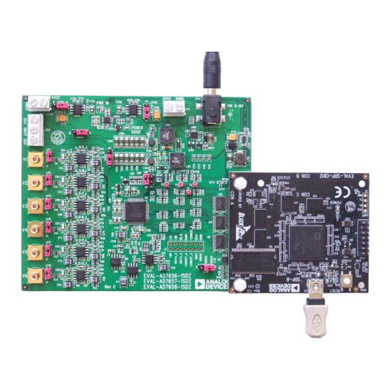
EVALUATION BOARD DESCRIPTION
This User Guide describes the evaluation board for the
AD7656-1/57-1/58-1 which are 16-/14-/12-, Six-Channel
Simultaneous
Sampling 250 ksps ADCs respectively. The AD7656-1/57-1/58-1
contains six 16-/14-/12- low power SAR ADCs. The parts
operate from a single 4.75V to 5.25V supply and dual ± 12V
power supply and feature throughput rates of up to 250 ksps.
Full details on the AD7656-1/57-1/58-1 are available in the
AD7656-1/57-1/58-1 datasheets which are available from
Analog Devices and should be consulted in conjunction with
this User Guide when using
the Evaluation Board.
On-board components include the:
AD8597: Ultralow Distortion, Ultralow Noise Op Amp
(single)
AD8031: 2.7 V, 800 μA, 80 MHz Rail-to-Rail I/O Single
Amplifier
ADP1613: Step-Up PWM DC-to-DC Switching
Converter,
PLEASE SEE THE LAST PAGE FOR AN IMPORTANT
WARNING AND LEGAL TERMS AND CONDITIONS.
Evaluating the AD7656-1/57-1/58-1
Rev. PrA | Page 1 of 32
Evaluation Board User Guide
UG-AD7656-1/57-1/58-1
EVAL-AD7656-1/57-1/58-1SDZ KIT CONTENTS
EVAL-AD7656-1/57-1/58-1SDZ Evaluation Board
Evaluation Software CD for the AD7656-1/57-1/58-1
9V Mains power supply adapter
ADDITIONAL EQUIPMENT NEEDED
System Demonstration platform (EVAL-SDP-CB1Z)
Precision Analog signal source
SMB cables
USB Cables
ADP3303-5: High Accuracy anyCAP™ 200 mA Low
Dropout Linear Regulator
ADP2301: 1.2 A, 20 V, 1.4 MHz non-synchronous step-
down switching regulator
ADM1185: Quad Voltage Monitor and Sequencer
ADP190: Logic Controlled, High-Side Power Switch
ADG3308: Low Voltage, 1.15 V to 5.5 V, 8-Channel
Bidirectional Logic Level Translator
ADR431: Ultralow Noise XFET® Voltage References
with Current Sink and Source Capability
AD780: 2.5 V/3.0 V Ultrahigh Precision Bandgap
Voltage Reference.
Various link options are described in the Evaluation Board
Hardware section.
Advertisement
Table of Contents

Related Manuals for Analog Devices EVAL-AD7656-1SDZ


Summary of Contents for Analog Devices EVAL-AD7656-1SDZ
-
Page 1: Features
Full details on the AD7656-1/57-1/58-1 are available in the AD7656-1/57-1/58-1 datasheets which are available from ADG3308: Low Voltage, 1.15 V to 5.5 V, 8-Channel Analog Devices and should be consulted in conjunction with Bidirectional Logic Level Translator this User Guide when using ADR431: Ultralow Noise XFET®... -
Page 2: Functional Block Diagram
AD8597 PARALLEL ADG3308 AD7656-1 LEVEL INTERFACE DB0..15 SHIFTERS AD8597 RESET RANGE EVAL-SDP-CB1Z AD8597 REFIN/ REFCAPA.. SER/PAR_SEL REFOUT REFCAPC H/S_SEL HARDWARE CONTROLLER SELECT BOARD AD8597 AD780/ ADR431 AD8597 EVAL-AD7656-1SDZ Figure 1 Functional Block Diagram Rev. PrA | Page 2 of 32... -
Page 3: Table Of Contents
Evaluation Board User Guide UG-AD7656-1/57-1/58-1 TABLE OF CONTENTS Features ....................1 Reference Options ............... 11 EVAL-AD7656-1/57-1/58-1SDZ KIT Contents ....... 1 Sockets/Connectors ..............12 Additional Equipment Needed ............1 EVAL-AD7656-1/57-1/58-1SDZ Basic Hardware Setup ..13 ... -
Page 4: Eval-Ad7656-1/57-1/58-1Sdz Quickstart Guide
AD7656-1/57-1/58-1SDZ board as shown in Figure (6) Launch the EVAL-AD7656-1/57-1/58-1SDZ software 1Figure 2. from the Analog Devices subfolder in the Programs (3) Screwing the two boards together with the enclosed menu. nylon screw-nut set will ensure the boards connect firmly together. -
Page 5: Evaluation Board Hardware
Evaluation Board User UG-AD7656-1/57-1/58-1 Guide EVALUATION BOARD HARDWARE The AD7656-1/AD7657-1/AD7658-1 feature throughput rates of up to 250 kSPS. The parts contain low noise, wide bandwidth AD7656-1/57-1/58-1 DEVICE DESCRIPTION track-and-hold amplifiers that can handle input frequencies The AD7656-1/AD7657-1/AD7658-1 are reduced decoupling up to 4.5 MHz. -
Page 6: Hardware Link Options
Evaluation Board User UG-AD7656-1/57-1/58-1 Guide HARDWARE LINK OPTIONS There are 23 link options, which must be set for the required operating setup before using the evaluation board. The functions of these options are outlined in Table 1. Shows the position in which all the links are set when the evaluation board is packaged. Jumper and solder link (LKx) options must be set correctly to select the appropriate operating setup before using the evaluation board. - Page 7 Evaluation Board User UG-AD7656-1/57-1/58-1 Guide Link No. Function LK15 V4 input jumper. When inserted input is shorted to GND. LK16 VDRIVE Source Signal Selection Position A: Sourced from onboard 3.3V. (Requires the SDP1Z board to be connected) . Position B: Connected to external socket J7-14. LK17 V5 input jumper.
- Page 8 Evaluation Board User UG-AD7656-1/57-1/58-1 Guide Link No. Function DB2 / SEL_C Selection Position A: data to EVAL-SDP1Z. LK31 Position B: Connected to VDRIVE. Position C: Connected to GND. LK32 DB1 / SEL_B Selection Position A: data to EVAL-SDP1Z. Position B: Connected to VDRIVE. Position C: Connected to GND.
- Page 9 Evaluation Board User UG-AD7656-1/57-1/58-1 Guide Link No. Function SL15 V1 Buffer Selection Position A: Input signal buffered through U4 Position B: Input signal taken directly from J1 SL16 V2 Buffer Selection Position A: Input signal buffered through U7 Position B: Input signal taken directly from J2 SL17 V3 Buffer Selection Position A: Input signal buffered through U8...
- Page 10 Evaluation Board User UG-AD7656-1/57-1/58-1 Guide LK26 Connected to EVAL-SDP1Z LK27 Connected to EVAL-SDP1Z LK28 Connected to EVAL-SDP1Z LK29 Connected to EVAL-SDP1Z LK30 Connected to EVAL-SDP1Z LK31 Connected to EVAL-SDP1Z LK32 Connected to EVAL-SDP1Z LK33 Connected to EVAL-SDP1Z LK34 Connected to EVAL-SDP1Z LK35 Connected to EVAL-SDP1Z CONVST_A CONVST_C not linked...
-
Page 11: Power Supplies
Evaluation Board User UG-AD7656-1/57-1/58-1 Guide POWER SUPPLIES PARALLEL INTERFACE Care should be taken before applying power and signals to the evaluation board to ensure that all link positions are as required The AD7656-1/57-1/58-1 uses a high-speed parallel interface, by the operating mode. which allows sampling rates up to 250kSPS. -
Page 12: Sockets/Connectors
Evaluation Board User UG-AD7656-1/57-1/58-1 Guide SOCKETS/CONNECTORS Table 4 Socket connector functions Socket Function VIN0 Analog input VIN0. Buffered to VIN0 on AD7656-1/57-1/58-1. VIN1 Analog input VIN1. Buffered to VIN1 on AD7656-1/57-1/58-1. VIN2 Analog input VIN2. Buffered to VIN2 on AD7656-1/57-1/58-1. VIN3 Analog input VIN3. -
Page 13: Eval-Ad7656-1/57-1/58-1Sdz Basic Hardware Setup
Evaluation Board User UG-AD7656-1/57-1/58-1 Guide Once the EVAL-AD7656-1/57-1/58-1SDZ board and the EVAL- EVAL-AD7656-1/57-1/58-1SDZ BASIC SDP-CB1Z board are connected securely, connect the power HARDWARE SETUP supplies on the EVAL-AD7656-1/57-1/58-1SDZ board. The The AD7656-1/57-1/58-1 evaluation board connects to the EVAL-AD7656-1/57-1/58-1SDZ requires an external power (EVAL-SDP-CB1Z) System Demonstration Board. -
Page 14: Evaluation Board Software
The EVAL-AD7656-1/57-1/58-1SDZ evaluation kit includes software on a CD. Click the setup.exe file from the CD to run the install. The default location for the software is C:\Program Files\Analog Devices\AD7656-1_57-1_58-1 Note: Install the evaluation software before connecting the evaluation board and EVAL-SDP-CB1Z board to the USB port of the PC to ensure that the evaluation system is correctly recognized when connected to the PC. - Page 15 Evaluation Board User UG-AD7656-1/57-1/58-1 Guide Figure 10. ADI EVAL-SDP-CB1Z Drivers Setup Window 3 Figure 7. AD7656-1/57-1/58-1 Install Window 5. Figure 11. ADI EVAL-SDP-CB1Z Drivers Setup Window 4 Figure 8. ADI EVAL-SDP-CB1Z Drivers Setup Window 1. Figure 12. ADI EVAL-SDP-CB1Z Drivers Setup Window 5 Figure 9.
-
Page 16: Launching The Software
To launch the software, complete the following steps: has connected correctly by looking at the Device Manager of From the Start menu, select Programs ->Analog Devices - the PC. The Device Manager can be found by right clicking on > AD7656-1/57-1/58-1. The main window of the software My Computer->Manage ->Device Manager from the list of... -
Page 17: Description Of User Software Panel
Evaluation Board User UG-AD7656-1/57-1/58-1 Guide Figure 15. Setup Screen Voltage range. Use this in conjunction with hardware DESCRIPTION OF USER SOFTWARE PANEL settings. The user software panel as shown in Figure 15 has the following Sampling Rate. The default sampling frequency will match features: the max sample rate of the ADC selected from the drop File menu with choice of;... - Page 18 Evaluation Board User UG-AD7656-1/57-1/58-1 Guide There are four tabs available displaying the data in different 10. This LED indicates when a read is in progress from the formats, this are listed here and described in more detail EVAL-SDP-CB1Z board. later. 11.
-
Page 19: Waveform Capture
Evaluation Board User UG-AD7656-1/57-1/58-1 Guide Figure 16. Waveform Capture Tab The waveform analysis reports back the amplitudes recorded WAVEFORM CAPTURE from the captured signal in addition to the frequency of the Figure 16 illustrates the waveform capture tab. The input signal signal tone. -
Page 20: Ac Testing - Histogram
Evaluation Board User UG-AD7656-1/57-1/58-1 Guide Figure 17. Histogram Capture Tab Illustrates the different measured values for the data AC TESTING - HISTOGRAM captured. Figure 17 shows the histogram capture tab. This tests the ADC DC TESTING - HISTOGRAM for the code distribution for AC input and computes the mean and standard deviation, or transition noise of the converter and More commonly, the histogram would be used for DC testing. -
Page 21: Ac Testing - Fft Capture
Evaluation Board User UG-AD7656-1/57-1/58-1 Guide Figure 18. FFT Capture Tab filter when the full-scale input range is more than a few Vpp, it AC TESTING - FFT CAPTURE is recommended to use the on board amplifiers to amplify the Figure 18 shows the FFT capture tab This tests the traditional signal, thus preventing the filter from distorting the input AC characteristics of the converter and displays a Fast Fourier signal. -
Page 22: Summary Tab
Evaluation Board User UG-AD7656-1/57-1/58-1 Guide Figure 19. Summary Tab SUMMARY TAB Figure 19 shows the summary tab The summary tab captures all the display information and provides them in one panel with a synopsis of the information including key performance parameters such as SNR and THD Rev. -
Page 23: Save File
Evaluation Board User UG-AD7656-1/57-1/58-1 Guide SAVE FILE LOAD FILE See Figure 20 The software can save the current captured data See Figure 21 User is prompted with a load dialog box. User for later analysis; the file format is .tsv (tab-separated values). may have to navigate to find these example files. -
Page 24: Evaluation Board Schematics And Artwork
Evaluation Board User UG-AD7656-1/57-1/58-1 Guide EVALUATION BOARD SCHEMATICS AND ARTWORK Figure 22. Schematic page 1 Rev. PrA | Page 24 of 32... - Page 25 Evaluation Board User UG-AD7656-1/57-1/58-1 Guide Figure 23. Schematic page 2 Rev. PrA | Page 25 of 32...
- Page 26 Evaluation Board User UG-AD7656-1/57-1/58-1 Guide Figure 24. Schematic page 3 Rev. PrA | Page 26 of 32...
- Page 27 Evaluation Board User UG-AD7656-1/57-1/58-1 Guide Figure 25 Schematic page 4 Rev. PrA | Page 27 of 32...
- Page 28 Evaluation Board User UG-AD7656-1/57-1/58-1 Guide Figure 26 Schematic page 5 Rev. PrA | Page 28 of 32...
- Page 29 Evaluation Board User UG-AD7656-1/57-1/58-1 Guide Figure 27. Top Printed Circuit Board (PCB) Silkscreen Figure 28 Bottom Printed Circuit Board (PCB) Silkscreen Rev. PrA | Page 29 of 32...
- Page 30 Evaluation Board User UG-AD7656-1/57-1/58-1 Guide Figure 29. Layer 1 Component side view Figure 30. Layer 2 Component Side view Rev. PrA | Page 30 of 32...
- Page 31 Evaluation Board User UG-AD7656-1/57-1/58-1 Guide Figure 31 Layer 3 Component side view Figure 32 Layer 4Component side view Rev. PrA | Page 31 of 32...
- Page 32 By using the evaluation board discussed herein (together with any tools, components documentation or support materials, the “Evaluation Board”), you are agreeing to be bound by the terms and conditions set forth below (“Agreement”) unless you have purchased the Evaluation Board, in which case the Analog Devices Standard Terms and Conditions of Sale shall govern. Do not use the Evaluation Board until you have read and agreed to the Agreement.
Need help?
Do you have a question about the EVAL-AD7656-1SDZ and is the answer not in the manual?
Questions and answers