Table of Contents
Advertisement
Quick Links
UG_201703_PL17_05
User guide for IRDC38263 evaluation board
OptiMOS™ iPOL
About this document
Scope and purpose
The IR38263 OptiMOS
SVID and I2C/SMBus interface. The onboard PWM controller and low duty cycle optimized MOSFETs make
IR38263 a space-efficient solution, providing accurate power delivery for low output voltage and high current
applications.
IR38263 is a versatile regulator which offers programmability of switching frequency, output voltage, and
fault/warning thresholds and fault responses while operating over a wide input and output voltage range. Thus, it
offers flexibility as well as system level security in event of fault conditions.
The switching frequency is programmable from 166 kHz to 1.5 MHz for an optimum solution. The on-chip
sensors and ADC along with the SVID and PMBus interfaces make it easy to monitor and report input voltage,
output voltage, output current and temperature.
This user guide contains the schematic and bill of materials for the IRDC38263 evaluation board. The guide
describes the use of the evaluation board itself. Detailed application information for IR38263 is available in the
IR38263 data sheet
Intended audience
This user guide is intended as a reference for designer's evaluating the IRDC38263 board, OptiMOS™ iPOL.
Table of Contents
About this document ............................................................................................................................1
Table of Contents .................................................................................................................................1
1
Board features ....................................................................................................................3
2
Connections and operating instructions ............................................................................... 4
3
Bill of materials .................................................................................................................. 9
4
Typical operating waveforms .............................................................................................11
4.1
Waveforms (0.72V) ........................................................................................................................... 11
4.2
Waveforms (1.0V)............................................................................................................................. 15
4.3
Waveforms (1.8V).............................................................................................................................19
4.4
Bode Plots (0.72V) ............................................................................................................................22
4.5
Bode Plots (1.0V) ..............................................................................................................................23
4.6
Bode Plots (1.8V) ..............................................................................................................................24
4.7
Thermal Image (0.72V) .....................................................................................................................25
4.8
Thermal Imafe (1.0V)........................................................................................................................26
4.9
Thermal Image (1.8V) .......................................................................................................................26
4.10
Efficiency and Power Loss (0.72V) ....................................................................................................28
4.11
Efficiency and Power Loss (1.0V) ......................................................................................................29
4.12
Efficiency and Power Loss (1.8V) ......................................................................................................30
Application Note
www.infineon.com
TM
iPOL is an easy-to-use, fully integrated and highly efficient DC/DC regulator with Intel
Please read the Important Notice and Warnings at the end of this document
<Revision 1.1>
<2017-10-04>
Advertisement
Table of Contents

Related Manuals for Infineon Technologies OptiMOS IR38263


Summary of Contents for Infineon Technologies OptiMOS IR38263
-
Page 1: Table Of Contents
UG_201703_PL17_05 User guide for IRDC38263 evaluation board OptiMOS™ iPOL About this document Scope and purpose The IR38263 OptiMOS iPOL is an easy-to-use, fully integrated and highly efficient DC/DC regulator with Intel SVID and I2C/SMBus interface. The onboard PWM controller and low duty cycle optimized MOSFETs make IR38263 a space-efficient solution, providing accurate power delivery for low output voltage and high current applications. - Page 2 User guide for IRDC38263 evaluation board OptiMOS™ iPOL Board features Revision History ..........................31 Application Note <Revision 1.1> <2017-10-04>...
-
Page 3: Board Features
User guide for IRDC38263 evaluation board OptiMOS™ iPOL Board features Board features = +12 V • Vout = +0.72 V to +1.8 V • Idc = 30 A • = 762 kHz • L = 120 nH (10.2 mm X 7 mm X 4.96 mm, DCR=0.39 mΩ) •... -
Page 4: Connections And Operating Instructions
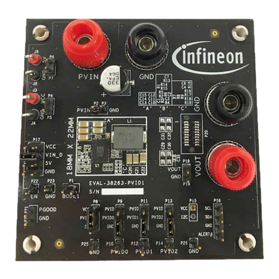
User guide for IRDC38263 evaluation board OptiMOS™ iPOL Connections and operating instructions Connections and operating instructions IR38163 VCCIO demo board requires a single +12 V for the input power. It can deliver up to 30 A load current. Table 1 lists the connectors, jumpers and test points on the board. Table 1 Connections Label... - Page 5 User guide for IRDC38263 evaluation board OptiMOS™ iPOL Connections and operating instructions Figure 1 Top view of IR38263 evaluation board The PCB of IR38263 demo board is a 3”x 3” 8-layer board using FR4 material. All layers use 2 Oz. copper. Application Note <Revision 1.1>...
- Page 6 User guide for IRDC38263 evaluation board OptiMOS™ iPOL Connections and operating instructions Figure 2 Schematic of the IRDC38263 evaluation board Application Note <Revision 1.1> <2017-10-04>...
- Page 7 User guide for IRDC38263 evaluation board OptiMOS™ iPOL Connections and operating instructions Figure 3 Schematic of the IRDC38263 evaluation board Application Note <Revision 1.1> <2017-10-04>...
- Page 8 User guide for IRDC38263 evaluation board OptiMOS™ iPOL Connections and operating instructions Figure 4 Schematic of the IRDC38263 evaluation board Application Note <Revision 1.1> <2017-10-04>...
-
Page 9: Bill Of Materials
User guide for IRDC38263 evaluation board OptiMOS™ iPOL Bill of materials Bill of materials Table 3 Bill of materials Item Quantity Part Reference Value Description Manufacturer Part Number Number CAP CER 2200PF 25V 10% X7R 2200 pF Kemet C0402C222K3RACTU 0402 CAP CER 200PF 50V 5% NP0 GRM1555C1H201JA01 200 pF... - Page 10 User guide for IRDC38263 evaluation board OptiMOS™ iPOL Bill of materials STRAIGHT ANGLE, 1 POS HEADER, 0.100, SINGLE ROW, MALE, LGND BULK STRAIGHT ANGLE, 1 POS R1,R12,R13,R14,R16,R18,R20,R RES 0.0 OHM 1/10W 0402 SMD Panasonic ERJ-2GE0R00X 95.3 RES 95.3 OHM 1/10W 1% 0402 SMD Panasonic ERJ-2RKF95R3X 5.36 k...
-
Page 11: Typical Operating Waveforms
User guide for IRDC38263 evaluation board OptiMOS™ iPOL Typical operating waveforms Typical operating waveforms Waveforms (0.72V) PVin = 12.0 V, Vout = 0.72 V, Iout = 0 A-30 A, Fs=762 kHz, Room Temperature, no airflow Figure 5 Start up at 30 A Load, Ch , Ch , Ch , Ch... - Page 12 User guide for IRDC38263 evaluation board OptiMOS™ iPOL Typical operating waveforms Figure 7 Vo ripple at 30 A load, Ch Figure 8 Fig. 8: Prebias startup at 0.5 V, Ch , Ch Good Application Note <Revision 1.1> <2017-10-04>...
- Page 13 User guide for IRDC38263 evaluation board OptiMOS™ iPOL Typical operating waveforms Figure 9 Inductor node at 30 A load, Ch :SW node Figure 10 Sw node jitter at 30 A load, Ch :SW node Application Note <Revision 1.1> <2017-10-04>...
- Page 14 User guide for IRDC38263 evaluation board OptiMOS™ iPOL Typical operating waveforms PVin=12.0 V, Vout=0.72 V, Iout=0 A-30 A, Fs=762 kHz, Room Temperature, no airflow Figure 11 Load transient 3 A to 12 A at 2.5 A/us, Ch , Ch Figure 12 Load transient 21 A to 30 A at 2.5 A/us, Ch , Ch Application Note...
-
Page 15: Waveforms (1.0V)
User guide for IRDC38263 evaluation board OptiMOS™ iPOL Typical operating waveforms Waveforms (1.0V) PVin=12.0 V, Vout=1.0 V, Iout=0 A-30 A, Fs=762 kHz, Room Temperature, no airflow Figure 13 Start up at 30 A Load, Ch , Ch , Ch , Ch :Enable Good Figure 14... - Page 16 User guide for IRDC38263 evaluation board OptiMOS™ iPOL Typical operating waveforms Figure 15 Vo ripple at 30 A load, Ch Figure 16 Prebias startup at 0.9 V, Ch , Ch Good Application Note <Revision 1.1> <2017-10-04>...
- Page 17 User guide for IRDC38263 evaluation board OptiMOS™ iPOL Typical operating waveforms Figure 17 Inductor node at 30 A load, Ch :SW node Figure 18 Sw node jitter at 30 A load, Ch :SW node Application Note <Revision 1.1> <2017-10-04>...
- Page 18 User guide for IRDC38263 evaluation board OptiMOS™ iPOL Typical operating waveforms PVin=12.0 V, Vout=1.0 V, Iout=0 A-30 A, Fs=762 kHz, Room Temperature, no airflow Figure 19 Load transient 3 A to 12 A at 2.5 A/us, Ch , Ch Figure 20 Load transient 21 A to 30 A at 2.5 A/us, Ch , Ch Application Note...
-
Page 19: Waveforms (1.8V)
User guide for IRDC38263 evaluation board OptiMOS™ iPOL Typical operating waveforms Waveforms (1.8V) PVin=12.0 V, Vout=1.8 V, Iout=0 A-30 A, Fs=762 kHz, Room Temperature, no airflow Figure 21 Vo ripple at 30 A load, Ch Figure 22 Hiccup recovery at 30 A Load, Ch , Ch Good Application Note... - Page 20 User guide for IRDC38263 evaluation board OptiMOS™ iPOL Typical operating waveforms Figure 23 Inductor node at 30 A load, Ch :SW node Figure 24 Sw node jitter at 30 A load, Ch Application Note <Revision 1.1> <2017-10-04>...
- Page 21 User guide for IRDC38263 evaluation board OptiMOS™ iPOL Typical operating waveforms PVin=12.0 V, Vout=1.8 V, Iout=0 A-30 A, Fs=762 kHz, Room Temperature, no airflow Figure 25 Load transient 3 A to 12 A at 2.5 A/us, Ch , Ch Figure 26 Load transient 21 A to 30 A at 2.5A /us, Ch , Ch Application Note...
-
Page 22: Bode Plots (0.72V)
User guide for IRDC38263 evaluation board OptiMOS™ iPOL Typical operating waveforms Bode Plots (0.72V) PVin=12.0 V, Vout=0.72 V, Iout=0 A-30 A, Fs=762 kHz, Room Temperature, no airflow Figure 27 Bode Plot at 30 A load, Bandwidth = 99 kHz, Phase Margin = 52.4 , Gain Margin = 15.7 dB Figure 28 Bode Plot at 0 A load, Bandwidth = 93 kHz, Phase Margin = 83... -
Page 23: Bode Plots (1.0V)
User guide for IRDC38263 evaluation board OptiMOS™ iPOL Typical operating waveforms Bode Plots (1.0V) PVin=12.0 V, Vout=1.0 V, Iout=0 A-30 A, Fs=762 kHz, Room Temperature, no airflow Figure 29 Bode Plot at 30 A load, Bandwidth = 98 kHz, Phase Margin = 52.6 , Gain Margin = 16.5 dB Figure 30 Plot at 0 A load, Bandwidth = 100 kHz, Phase Margin = 69.9... -
Page 24: Bode Plots (1.8V)
User guide for IRDC38263 evaluation board OptiMOS™ iPOL Typical operating waveforms Bode Plots (1.8V) PVin=12.0 V, Vout=1.8 V, Iout=0 A-30 A, Fs=762 kHz, Room Temperature, no airflow Figure 31 Bode Plot at 30 A load, Bandwidth = 127 kHz, Phase Margin = 49.2 , Gain Margin = 12.4 dB Figure 32 Bode Plot at 0 A load, Bandwidth = 134 kHz, Phase Margin = 81... -
Page 25: Thermal Image (0.72V)
User guide for IRDC38263 evaluation board OptiMOS™ iPOL Typical operating waveforms Thermal Image (0.72V) PVin=12.0 V, Vout=0.72 V, Iout=30 A, Fs=762 kHz, Room Temperature, no airflow Figure 33 Thermal Image of the board at 30 A load, IR38263: 86.5 C, inductor: 82.3 Application Note <Revision 1.1>... -
Page 26: Thermal Imafe (1.0V)
User guide for IRDC38263 evaluation board OptiMOS™ iPOL Typical operating waveforms Thermal Imafe (1.0V) PVin=12.0 V, Vout=1.0 V, Iout=30 A, Fs=762 kHz, Room Temperature, no airflow Figure 34 Thermal Image of the board at 30 A load, IR38263: 90.7 C, inductor: 87 Thermal Image (1.8V) PVin=12.0 V, Vout=1.8 V, Iout=30 A, Fs=762 kHz, Room Temperature, no airflow Application Note... - Page 27 User guide for IRDC38263 evaluation board OptiMOS™ iPOL Typical operating waveforms Figure 35 Thermal Image of the board at 30 A load, IR38263: 93.8 C, inductor: 91 Application Note <Revision 1.1> <2017-10-04>...
-
Page 28: Efficiency And Power Loss (0.72V)
User guide for IRDC38263 evaluation board OptiMOS™ iPOL Typical operating waveforms 4.10 Efficiency and Power Loss (0.72V) PVin=12.0 V, Vout=0.72 V, Iout=0 A-30 A, Fs=762 kHz, Room Temperature, no airflow Figure 36 Efficiency vs. load current Figure 37 Power Loss vs. load current Application Note <Revision 1.1>... -
Page 29: Efficiency And Power Loss (1.0V)
User guide for IRDC38263 evaluation board OptiMOS™ iPOL Typical operating waveforms 4.11 Efficiency and Power Loss (1.0V) PVin=12.0 V, Vout=1.0 V, Iout=0 A-30 A, Fs=762 kHz, Room Temperature, no airflow Figure 38 Efficiency vs. load current Figure 39 Power Loss vs. load current Application Note <Revision 1.1>... -
Page 30: Efficiency And Power Loss (1.8V)
User guide for IRDC38263 evaluation board OptiMOS™ iPOL Typical operating waveforms 4.12 Efficiency and Power Loss (1.8V) PVin=12.0 V, Vout=1.8 V, Iout=0 A-30 A, Fs=762 kHz, Room Temperature, no airflow Figure 40 Efficiency vs. load current Figure 41 Power Loss vs. load current Application Note <Revision 1.1>... - Page 31 User guide for IRDC38263 evaluation board OptiMOS™ iPOL Revision History Revision History Major changes since the last revision Page or Reference Description of change Rev 1.1 Updated C4 capacitor from 2.2uF to the recommended 10uF. Application Note <Revision 1.1> <2017-10-04>...
- Page 32 Published by product only and shall in no event be regarded as a contact your nearest Infineon Technologies office description or warranty of a certain functionality, (www.infineon.com). Infineon Technologies AG condition or quality of the product.
Need help?
Do you have a question about the OptiMOS IR38263 and is the answer not in the manual?
Questions and answers