Table of Contents
Advertisement
Quick Links
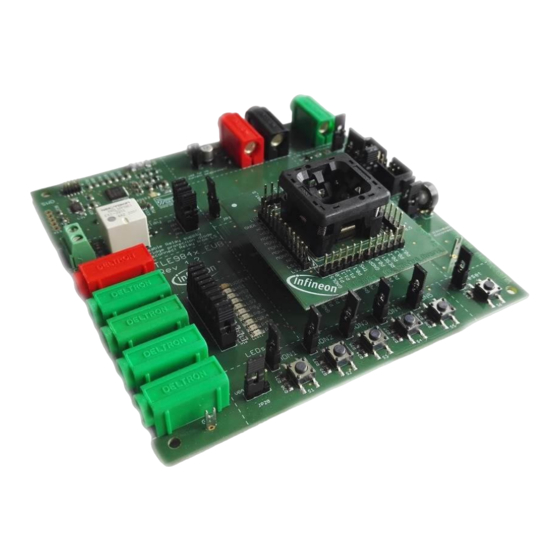
T L E 9 8 4 x E v a l b o a r d R e v 1 . 3 U s e r M a n u a l
Figure 1
About this document
Scope and purpose
The TLE984x Evalboard is designed to evaluate hardware and software functionalities of the TLE984x
device family. All Pins of the chip are able to be contacted via Pinheader. Further the bidirectional Relay can be
used to evaluate DC motor applications.
This Manual provides additional information about the Boards Layout, Jumper settings, interfaces and Debug
options. It introduces the Evaluation Plattform as well as how to create a software example and download it to
the TLE984x.
Note:
This Evaluationboard is not optimized for EMC behavior.
Intended audience
This Document is for everyone who works with the TLE984x_EVB.
Please read the Important Notice and Warnings at the end of this document
Rev. 1.0
www.infineon.com/embeddedpower
2016-10-24
Advertisement
Table of Contents

Related Manuals for Infineon Technologies TLE9842QX


Summary of Contents for Infineon Technologies TLE9842QX
- Page 1 T L E 9 8 4 x E v a l b o a r d R e v 1 . 3 U s e r M a n u a l Figure 1 About this document Scope and purpose The TLE984x Evalboard is designed to evaluate hardware and software functionalities of the TLE984x device family.
-
Page 2: Table Of Contents
User Manual TLE984x Evalboard Rev 1.3 Table of contents Table of contents About this document ............Preface-1 Table of contents . -
Page 3: Concept
User Manual TLE984x Evalboard Rev 1.3 Concept Concept Figure 1 Evalboard Concept This board is designed to provide a fast and easy start of evaluation, for Infineons embedded Power TLE984x device family. Initialy, the evaluation board brings several interfaces and interconnections shown in Figure 1. The TLE984x device is placed in the center of the PCB. -
Page 4: Interconnections
User Manual TLE984x Evalboard Rev 1.3 Interconnections Interconnections Figure 2 Interconnections 4mm Laboratory Connectors Ground, voltagesupply (operating Voltage is documented in the datasheet) and LIN communication can be connected via banana jacks: GND (black), VBAT (red), LIN (green) VDDEXT, HS- and LS-switch signals can also be accessed with laboratory equipment: VDDEXT(red), HS1(green), HS2(green), LS1(green), LS2(green). -
Page 5: Jumper Settings
User Manual TLE984x Evalboard Rev 1.3 Jumper Settings Jumper Settings Figure 3 Jumper Settings Figure 3 shows the jumper positions on the Evaluation Board. The color of gives an information about the voltage, which can appear at the Jumperpins. Green marked jumper are related to the 5V domain (voltage range 0V...VDDP/VDDEXT). Blue marked jumper are related to high voltage Inputs or Outputs of the TLE984x. - Page 6 User Manual TLE984x Evalboard Rev 1.3 Jumper Settings Table 1 Jumper List Jumper Number Signal Name Description and Board connection Relay coil K1 Relay coil K2 P0.2 LED8 P0.3 LED9 P0.4 LED10 JP10 P1.2 LED11 JP11 P1.4 LED12 JP12 LED6 JP13 LED7 JP14...
-
Page 7: Communication Interfaces
User Manual TLE984x Evalboard Rev 1.3 Communication Interfaces Communication Interfaces LIN and uIO for LIN BSL The device integrated LIN transceiver is connected to a banana jack and additionally to the uIO BSL interface. To integrate the device in a LIN network it is sufficient to use the single wire banana interface. The BSL interface is intended to program the device via LIN. -
Page 8: Software Toolchain
User Manual TLE984x Evalboard Rev 1.3 Software Toolchain Software Toolchain Keil µVision 5 The recommended Integrated Software Developement Environment is Keil® µVision5®. Infineons embedded Power family is suported. For more information about the Toolchain go to: www.keil.com Infineon Config Wizard In addition to the IDE, Infineon®... - Page 9 User Manual TLE984x Evalboard Rev 1.3 Software Toolchain If the board has been connected successfully, the ARM IDCODE will be visible in the SW Device Window. If connection fails, “Connect & Reset Options” and “Port” window has to be checked. Rev.
-
Page 10: Pcb Design Data
User Manual TLE984x Evalboard Rev 1.3 PCB Design Data PCB Design Data This Chapter contains Schematic- and Layout-Data. Schematic Figure 6 TLE984x Circuit and peripheral components Note: This is a very simplified example of an application circuit and bill of material. The function must be verified in the application. - Page 11 User Manual TLE984x Evalboard Rev 1.3 PCB Design Data Figure 7 Onboard debug cicuit Note: This is a very simplified example of an application circuit and bill of material. The function must be verified in the application. Rev. 1.0 2016-10-24...
-
Page 12: Layout Data
User Manual TLE984x Evalboard Rev 1.3 PCB Design Data Layout Data Figure 8 Parts placement Note: This is a very simplified example of an application circuit and bill of material. The function must be verified in the application. Rev. 1.0 2016-10-24... - Page 13 User Manual TLE984x Evalboard Rev 1.3 PCB Design Data Figure 9 Full Layout Note: This is a very simplified example of an application circuit and bill of material. The function must be verified in the application. Rev. 1.0 2016-10-24...
-
Page 14: Partlist
User Manual TLE984x Evalboard Rev 1.3 PCB Design Data Partlist Table 2 Evalboard Partlist Part Number Value Package 22µF ELKO_SMD_ALU_BF-C C2, C4, C5, C10, C11, C18, C19, C20, 100nF 0805 C21, C22, C33, C37 4.7µF 0805 C7, C15 2.2nF 0805 C8, C9 330nF 0805... - Page 15 User Manual TLE984x Evalboard Rev 1.3 PCB Design Data Table 2 Evalboard Partlist Part Number Value Package R21, R23, R25, R27, R29 0805 R30, R31 160R 0805 150R 0805 680R 0805 R3, R32, R34, R37, R50, R53, R54 0805 R56, R35 0805 S1, S2, S3, S4, S5, S6 Button...
-
Page 16: References
User Manual TLE984x Evalboard Rev 1.3 References References [1] TLE9842QX Data Sheet Rev. 1.0 [2] TLE9842-2QX Data Sheet Rev. 1.0 [3] TLE9843QX Data Sheet Rev. 1.0 [4] TLE9843-2QX Data Sheet Rev. 1.0 [5] TLE9844QX Data Sheet Rev. 1.0 [6] TLE9844-2QX Data Sheet Rev. 1.0 [7] TLE9845QX Data Sheet Rev. -
Page 17: Revision History
User Manual TLE984x Evalboard Rev 1.3 Revision History Revision History Revision History Page or Item Subjects (major changes since previous revision) Rev 1.0 Update from Eval Rev1.2 to Eval Rev1.3 RevisionHistory-1 Rev. 1.0 2016-10-24... - Page 18 Infineon Technologies, Infineon Technologies in customer's applications. Infineon Technologies’ products may not be used in Document reference The data contained in this document is exclusively any applications where a failure of the product or any Doc_Number intended for technically trained staff.
- Page 19 Mouser Electronics Authorized Distributor Click to View Pricing, Inventory, Delivery & Lifecycle Information: Infineon TLE984XEVALBOARDTOBO1...
Need help?
Do you have a question about the TLE9842QX and is the answer not in the manual?
Questions and answers