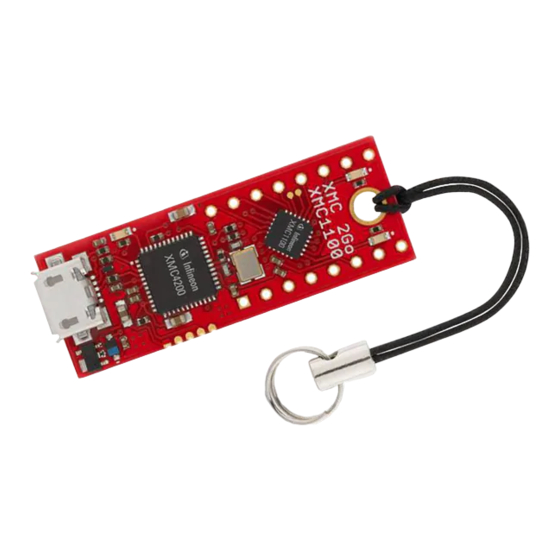
Summary of Contents for Infineon Technologies XMC 2Go
- Page 1 E valu atio n B oar d For XMC1000 Family XM C 2 Go Kit wit h X M C11 00 Kit Version 1.0 Boa rd Us er‘s Ma nu al Revision 1.0, 2014-02-20 Mic rocon t rolle r...
- Page 2 Infineon Technologies components may be used in life-support devices or systems only with the express written approval of Infineon Technologies, if a failure of such components can reasonably be expected to cause the failure of that life-support device or system or to affect the safety or effectiveness of that device or system. Life support devices or systems are intended to be implanted in the human body or to support and/or maintain and sustain and/or protect human life.
- Page 3 XMC 2Go XMC 2Go Kit with XMC1100 Revision History Page or Item Subjects (major changes since previous revision) Revision 1.0, Initial release 2014-02-20 Trademarks of Infineon Technologies AG AURIX™, C166™, CanPAK™, CIPOS™, CIPURSE™, EconoPACK™, CoolMOS™, CoolSET™, CORECONTROL™, CROSSAVE™, DAVE™, EasyPIM™, EconoBRIDGE™, EconoDUAL™, EconoPIM™, EiceDRIVER™, eupec™, FCOS™, HITFET™, HybridPACK™, I²RF™, ISOFACE™, IsoPACK™, MIPAQ™,...
-
Page 4: Table Of Contents
XMC 2Go XMC 2Go Kit with XMC1100 Table of Contents Table of Contents Introduction ................................7 Overview ............................. 7 Key Features ............................7 Block Diagram ............................8 Hardware Description ........................9 Power Supply ............................9 Pin Header Connector ........................10 User LEDs ............................ - Page 5 Pinning of Pin Header ........................10 Figure 4 Recommended Installation Options for the J-Link driver ..............11 Figure 5 Schematic of the XMC 2Go Kit with XMC1100 .................. 12 Figure 6 Components Placement and Geometry ..................... 13 Board Users Manual...
- Page 6 XMC 2Go Kit with XMC1100 List of Tables List of Tables Table 1 Features of the XMC 2Go Kit with XMC1100 ..................7 Table 2 Pins used for the User LEDs ......................10 Table 3 XMC1100 Pins used for Debugging and UART Communication ............11 Table 4 List of Material ............................
-
Page 7: Introduction
M0 based XMC1100 Microcontroller from Infineon Technologies AG. Overview The XMC 2Go is designed to evaluate the capabilities of the XMC1100 Microcontroller and the powerful, free of charge tool chain DAVE™. This board is not cost optimized and does not serve as a reference design. -
Page 8: Block Diagram
XMC 2Go Kit with XMC1100 Overview Block Diagram The block diagram in Figure 1 shows the main components of the XMC 2Go Kit including the power supply concept. There are following main building blocks: XMC1100 Microcontroller in a 4x4mm VQFN24 package ... -
Page 9: Hardware Description
Power Supply The XMC 2Go Kit must be supplied by an external 5 Volt DC power supply connected to the Micro UBS plugs (X101). Out of the box with the pre-programmed application and the on-board debugger in operation the XMC 2Go typically draws about 75 mA. -
Page 10: Pin Header Connector
Microcontroller in the TSSOP-16 pin package. The pinning table is also printed onto the bottom side of the PCB. Pin_Header.emf Figure 3 Pinning of Pin Header User LEDs The port pins P1.0 and P1.2 of the XMC1100 on the XMC 2Go Kit are connected to LEDs exclusively. Table 2 Pins used for the User LEDs Port Pin LED1 P1.1... -
Page 11: Debugging And Uart Communication
Recommended Installation Options for the J-Link driver The XMC1100 on the XMC 2Go Kit is configured to SWD1 mode. Use the “BMI Get Set” tool integrated into DAVE™ to configure the XMC1100 to e.g. SPD1 mode if required. Take care: Unintended use of the “BMI Get Set”... -
Page 12: Figure 5 Schematic Of The Xmc 2Go Kit With Xmc1100
XMC 2Go XMC 2Go Kit with XMC1100 Production Data Figure 5 Schematic of the XMC 2Go Kit with XMC1100 Board Users Manual Revision 1.0, 2014-02-20... -
Page 13: Components Placement And Geometry
XMC 2Go XMC 2Go Kit with XMC1100 Production Data Components Placement and Geometry IC201 D101 C202 D102 R107 C104 C201 R109 C106 R105 C101 R106 R101 C103 IC101 C107 LED101 R102 C102 C109 C105 C108 R108 Q101 C110 R104 R103... -
Page 14: List Of Material
XMC 2Go XMC 2Go Kit with XMC1100 Production Data List of Material The list of material is valid for the XMC 2Go Kit with XMC1100 Version 1. Table 4 List of Material Qty Value Device Reference Designator C1 C2 C101 C102 C103... - Page 15 . i n f i n e o n . c o m Published by Infineon Technologies AG...


Need help?
Do you have a question about the XMC 2Go and is the answer not in the manual?
Questions and answers